

Page 1
Technical InformationGas Cooktop
AKS3040* CGC2430AD* JGC6430AD* MGC5430BD* MGC6430BD*
• Due to possibility of personal injury or property damage, always contact an authorized technician for servicing or
repair of this unit.
• Refer to Service Manual 16022158 for detailed installation, operating, testing, troubleshooting, and disassembly
instructions.
CAUTION
!
All safety information must be followed as provided in Service Manual 16022158.
!
To avoid risk of electrical shock, personal injury or death; disconnect power to oven before servicing, unless
testing requires power.
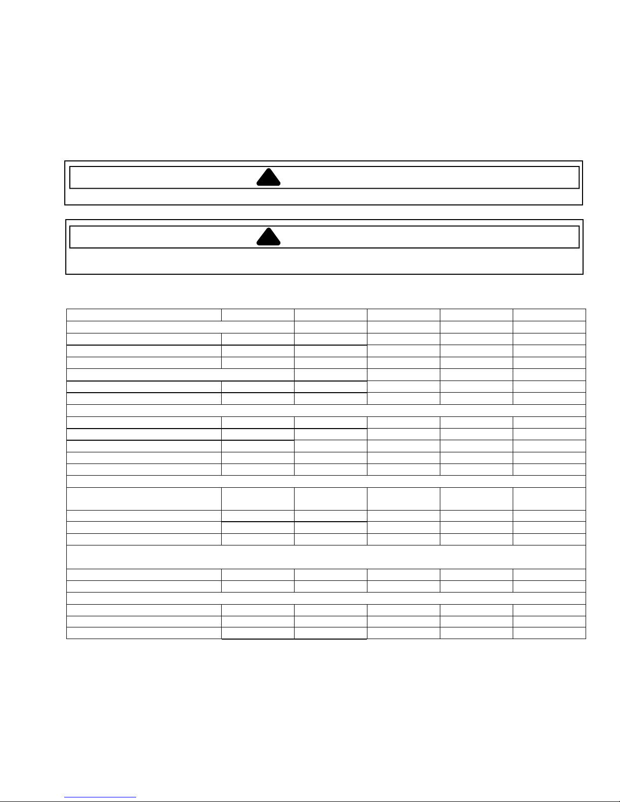
Model AKS3040* CGC2430AD* JGC6430AD* MGC5430BD* MGC6430BD*
Power Source
Voltage rating 120 VAC 120 VAC 120 VAC 120 VAC 120 VAC
Amperage rating 10 Amp 10 Amp 10 Amp 10 Amp 10 Amp
Frequency 60 Hz 60 Hz 60 Hz 60 Hz 60 Hz
Water Column Pressure
Natural 4 in. W.C.P. 4 in. W.C.P. 4 in. W.C.P. 4 in. W.C.P. 5 in. W.C.P.
LP/Propane 10 in. W.C.P. 10 in. W.C.P. 10 in. W.C.P. 10 in. W .C.P. 10 in. W.C.P.
Surface Burner (BTU Nat. / LP)
Type of burner Sealed Sealed Sealed Sealed Sealed
Right front 12.5 K/10.5 K 12.5 K/10.5 K 12.5 K/10.5 K 12.5 K/10.5 K 12.5 K/10.5 K
Right rear 9.2 K / 9.1 K 9.2 K / 9.1 K 9.2 K / 9.1 K 9.2 K / 9.1 K 9.2 K / 9.1 K
Left front 9.2 K / 9.1 K 9.2 K / 9.1 K 9.2 K / 9.1 K 9.2 K / 9.1 K 9.2 K / 9.1 K
Leftrear 5K/4K 9.2K/9.1K 5K/4K 5K/4K 5K/4K
Features
Grate sytle One-piece
continuous
Grates material Cast Heavy steel Heavy cast Cast Cast
Cooktop surface Porc/steel Porc/steel Temp glass Porc/steel Porc/steel
Electronicignition XXXXX
Product cutout dimensions
in. (cm)
Width 28.5 (72.4) 28.5 (72.4) 28.5 (72.4) 28.5 (72.4) 28.5 (72.4)
Depth 19.9 (50.6) 19.9 (50.6) 19.9 (50.6) 19.9 (50.6) 19.9 (50.6)
Nat / LP Orifice Spuds
12.5 K / 10.5 K 1.85 / 0.97 1.85 / 0.97 1.85 / 0.97 1.85 / 0.97 1.85 / 0.97
9.2 K / 9.1 K 1.55 / 0.91 1.55 / 0.91 1.55 / 0.91 1.55 / 0.91 1.55 / 0.91
5 K / 4 K 1.10 / 0.64 1.55 / 0.91 1.10 / 0.64 1.10 / 0.64 1.10 / 0.64
WARNING
Square One-piece
continuous
One-piece
continuous
One-piece
continuous
March 2003 16022195 Rev. 01
Page 2
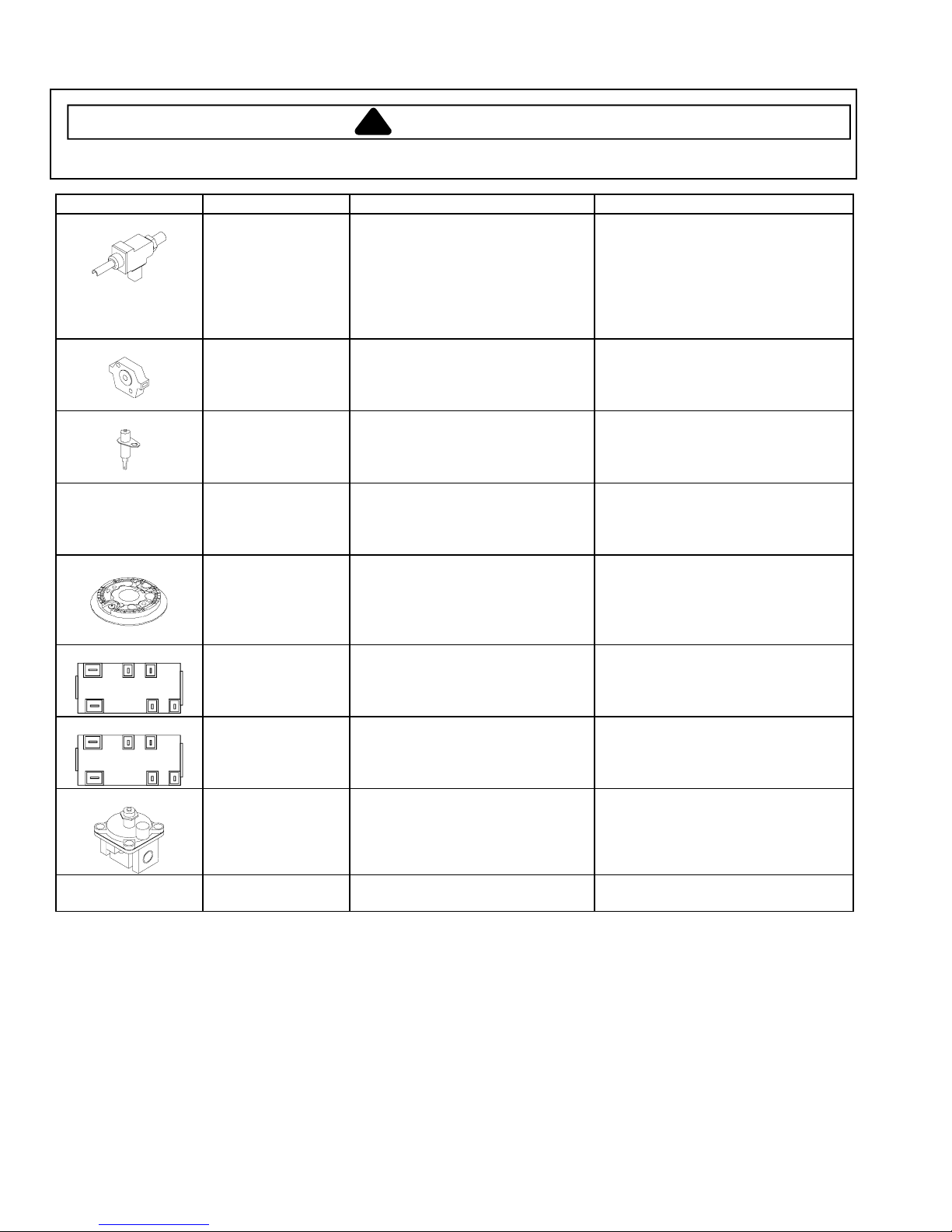
Component Testing Procedures
!
WARNING
To avoid risk of electrical shock, personal injury or death; disconnect power to oven before servicing, unless
testing requires power.
Illustration Component Test Procedure Results
270° valve
Verify gas is supplied.
To replace burner valve(s),
complete assembly must be
Orifice adjusted for
replaced (manifold and valves).
Natural or LP.
Adjust set screw for simmer
See conversion section.
control.
Spark 270° switch
Test for voltage at terminals.......
120 VAC
Disconnect wiring and check for
Spark ignition
continuity in LITE position...........
Test for resistance of spark lead
Continuity in LITE position.
Continuity
electrode
Test ignitor to chassis.................
No continuity from ignitor to
chassis.
Spark ignition
Test for resistance of spark lead
Continuity
electrode
Test ignitor to chassis.................
No continuity from ignitor to
chassis.
Top surface
burner
Verify gas is supplied..................
Check for obstructions in burner
ports.
Verify burner cap is positioned
correctly.
L
AB
B1N
A1
L
AB
B1N
A1
Spark module
4+0
Spark module
4+0
Pressure regulator Verify gas pressure (W.C.P.).
Test for voltage at terminals
L and N.......................................
Check polarity and ground..........
Test for voltage at terminals
L and N.......................................
Check polarity and ground..........
120 VAC
See wiring diagram
120 VAC
See wiring diagram
4" or 5" Natural, see specifications
10" LP/propane
If on LP service verify proper gas
supply conversion.
Power cord 3-wire Verify resistance of wires to
Continuity
terminals.
16022195 Rev. 0 March 20032
Page 3

Converting from Natural Gas to L.P. Gas
!
To avoid risk of electrical shock, personal injury or death; disconnect power to oven before servicing, unless
testing requires power.
Converting from Natural Gas to LP Gas
Converting the Burner Orifice Spuds
1. Remove the grates and burner caps.
2. Remove securing burner base to cooktop surface.
3. Remove the Natural Gas burner spud using a
9
/32" (7 mm) nut driver. Save spud to reconvert if
necessary in the future.
WARNING
3. Apply downward finger pressure at the disc edges to
place pin into the cap.
NAT
4. Place pressure regulator cap on pressure regulator
and tighten.
Low Flame Adjustment
Properly adjusted burner flames are clean and blue with
a distinct inner cone approximately ½ inch long.
1. Remove control knob from valve stem.
2. Carefully remove rubber grommet from cooktop.
3. Locate valve adjustment screw.
4. Insert a slender thin bladed screwdriver into knob
hole and engage blade with slot in adjusting screw.
5. Turnadjustingscrewclockwiseuntiltight(5–7in-lbs.
Max.). Do not over tighten.
6. Replace rubber grommet and control knob.
7. Repeat process for remaining burners.
Natural
LP
L.P.
4. Install the LP/Propane spud (included in literature
package).
NOTE: See Specifications Chart on first page for
location of components.
5. Tighten to a torque of orifice 15 to 20 inch-lbs.
6. Tighten burner base screws 25 to 30 inch-lbs.
7. Repeat steps 2 through 4 for each burner.
8. Replace burner caps and grates.
Converting Pressure Regulator for LP/Propane
1. Remove pressure regulator cap using a wrench.
2. Apply sideward finger pressure to remove pin from
cap.
Apply sideways
finger pressure
to remove pin
from cap
After adjusting the screw the burner should produce a
stable, steady blue flame of minimum size. The setting
should be checked by turning the knob from high to low
several times without extinguishing the flame.
This operation will automatically provide the proper flame
size at medium setting.
After conversion steps have been completed, check the
appearance of each burner flame at high and low
settings. If the flames appear too large or small, review
each step to verify it was completed correctly.
March 2003 16022195 Rev. 03
Page 4

Wiring Diagram and Schematic
!
To avoid risk of electrical shock, personal injury or death; disconnect power to oven before servicing, unless
testing requires power.
WARNING
SCHEMATIC
TOP BURNER
TOP IGNITORS
SPARK
MODULE
N
L
IGNITION SWITCHES
WIRING DIAGRAM
TOP BURNER
IGNITION SWITCHES
BLK BLK
BLK
TAN
NL
SPARK
MODULE
TOP IGNITORS
TAN TAN TAN
8104P828-60
BLK
NEUTRAL
POWER
CORD
GROUND
LINE
16022195 Rev. 0 March 20034
 Loading...