

Page 1

Maytag
MAYTJiC
Washer
Service Manual
16010358
(16009485)
Issued 5/99
Revised 6/01
Page 2

SAFETY PRECAUTIONS
This manual, as well as the information contained in it, is to be used only by a Maytag
Authorized Service Technician. They should be familiar with and knowledgeable of
proper safety and servicing procedures and possessing high quality testing equipment
associated with microwaves, gas, and electrical appliance repair.
All individuals who attempt repairs by improper means or adjustment subject them
selves and others to the risk of serious or fatal injury.
USE ONLY GENUINE MAYTAG APPROVED FACTORY REPLACEMENT COMPONENTS.
PRECAUTIONS TO BE OBSERVED BEFORE AND DURING SERVICING TO AVOID
POSSIBLE EXPOSURE TO EXCESSIVE DANGER AND ELECTRICAL SHOCK:
‘'1
1. Disconnect electrical supply before servicing machine.
2. If electricity is required for a test:
(A) First, disconnect electrical supply;
(B) Second, make any connections or adjustments required for the test;
(C) Third, connect electrical supply;
(D) Fourth, perform the test. If service is required, disconnect electrical
supply before servicing machine.
3. Please use caution when servicing the machine with the front panel
removed because there is danger of injury due to potential contact
with spinning transmission.
4. Please use caution when servicing the machine with the front panel
removed because there is danger of injury due to contact with a
potential "pinch point” between the turned up edge of the transmission
cover and the tub support flange.
Page 3

INTRODUCTION
The information presented in this manual is printed in a loose format and is divided into
sections relating to a general group of components and/or service procedures. Each
section is further subdivided to describe a particular component or service procedure.
Anything of a unique nature concerning these models has been detailed and labeled as
such in the manual.
The subdividing of the subject matter, plus the loose leaf form will facilitate the updating
of the manual as new or revised components are added or new models are introduced.
Each page of the manual will be identified in the lower right-hand corner, and as new or
revised pages are published, the manual can easily be updated by following the file
instructions on the cover letter of the supplement.
The service manual is a valuable tool and care should be taken to keep it up to date by
prompt and proper filing of subsequent pages as they are issued.
Model(s) covered in this service manual:
M
Brand M=Maytag
MAV4057 MAV7200
MAV4500 MAV7000
MAV5000 MAV7057
MAV5057 MAV7600
MAV6000 MAV7700
MAV6057 MAV8000
MAV6200 MAV8057
MAV6257 MAV8500
MAV6300 MAV8600
AV
Product
AV=Automatic
Vertical Washer
5000
Model No.
MAV9600
Production
Code
w w
Color
Q=Bisque
W=White
16010280
(16009485-02)
Voltage
W=120VAC/60 Hz-U.S.
Introduction
©2000 Maytag Appliances Sales Company
Page 4

For additional information on material covered in this manual, including safety issues,
contact:
Maytag Appliances Sales Company -
Customer Service
240 Edwards Street, S.E.
Cleveland, TIM 37311
Phone: 423.472.3333
FAX: 423.478.6722
* V
16010280
(16009485-02)
Introduction
©2000 Maytag Appliances Sales Company
Page 5

INTRODUCTION.................................................................................................Mi
CONTENTS...................................................................................................... iii-vl
SECTION 1. GENERAL INFORMATION
PRE-INSTALLATION REQUIREMENT....................................................................................1-1
ELECTRICAL REQUIREMENTS.............................................................................................1-1
GROUNDING INSTRUCTIONS................................................................................................1-2
UNCRATING INSTRUCTIONS............................................................................................... 1-2
INSTALLATION PROCEDURE................................................................................................ 1-3
FINAL INSTALLATION CHECK LIST.......................................................................................1-5
UNIQUE INSTALLATIONS.......................................................................................................1-5
SPECIFICATIONS....................................................................................................................1-7
CYCLE CHARTS......................................................................................................................1-9
SPECIAL TOOLS....................................................................................................................1-12
..........................................................
1-1
SECTION 2. OUTLINE OF MECHANICAL OPERATION................................2-1
GENERAL INFORMATION......................................................................................................2-1
CLUTCH ASSEMBLY.............................................................................................................. 2-1
DRIVE PULLEY AND CAMS................................................................................................ ..2-3
SECTION 3. EXPLODED VIEW OF COMPONENTS
SECTION 4. CABINET ASSEMBLY COMPONENTS
CONTROL PANEL ASSEMBLY
VERTICAL SWITCHES.............................................................................................................4-2
TIMER REMOVAL
AUTOMATIC TEMPERATURE CONTROL BOARD
TOP COVER ASSEMBLY.........................................................................................................4-3
STANDARD LID ASSEMBLY................................................................................................... 4-4
30 DAY DETERGENT DISPENSER.........................................................................................4-5
DETERGENT DISPENSING.....................................................................................................4-6
CLEANING THE DISPENSER..................................................................................................4-7
FRONT PANEL.........................................................................................................................4-7
REAR ACCESS PANEL........................................................................................................... 4-8
CABINET BODY ASSEMBLY................................................................................................. 4-9
BASE ASSEMBLY....................................................................................................................4-9
STABILIZER ASSEMBLY................................................................................................ .....4-11
TOP COVER TO CABINET HINGE........................................................................................4-12
....................................................................................................................4-2
....
..........................................................................................4-1
................................................................
......................................
.....................................
3-1
4-1
4-3
SECTION 5. WATER - RELATED COMPONENTS.........................................5-1
WATER MIXING VALVE.......................................................................................................... 5-1
WATER INLET FLUME.............................................................................................................5-2
AIR BELL.................................................................................................................................. 5-2
HOSES..................................................................................................................................... 5-2
16010280
(16009485-02)
©2000 Maytag Appliances Sales Company
Contents
III
Page 6

TUB TOP.................................................................................................................................. 5-3
AGITTVrOR..............................................................................................................................5-3
INNER TUB.............................................................................................................................. 5-4
OUTER TUB ASSEMBLY........................................................................................................5-4
PUMP ASSEMBLY..................................................................................................................5-5
WATER VALVE INJECTION SYSTEM....................................................................................5-7
STAINLESS STEEL SPINNER ASSEMLY..............................................................................5-9
SECTION 6. SUSPENSION SYSTEM.............................................................6-1
SUSPENSION HOUSING........................................................................................................6-2
TUB BRACES..........................................................................................................................6-2
SUSPENSION SPRINGS......................................................................................................... 6-2
SECTION 7. TRANSMISSION AND RELATED..............................................7-1
SEAL NUT ASSEMBLY...........................................................................................................7-2
UPPER BEARING AND SEAL HOUSING...............................................................................7-2
TUB SEAL................................................................................................................................7-3
TUB SEAL REPLACEMENT....................................................................................................7-3
UPPER SPIN BEARING..........................................................................................................7-4
DRIVE PULLEY AND CAMS...................................................................................................7-4
BRAKE AND SNUBBER ASSEMBLY..................................................................................... 7-7
TRANSMISSION ASSEMBLY COMPLETE (Non-Repairable)................................................7-9
TRANSMISSION HOUSING ASSEMBLY..............................................................................7-10
LOWER BEARING ASSEMBLY............................................................................................ 7-10
DIAGNOSING TRANSMISSION PROBLEMS
TORQUE TESTING...............................................................................................................7-12
TRANSMISSION REMOVAL................................................................................................. 7-14
......................................................................
7-12
SECTION 8. ELECTRICAL COMPONENTS & TESTING
..............................
8-1
ELECTRICAL TEST EQUIPMENT.......................................................................................... 8-1
ELECTRICAL TEST.................................................................................................................8-2
TIMER......................................................................................................................................8-2
TIMER SEQUENCE CHART................................................................................................... 8-3
AUTOMATIC TEMPERATURE CONTROL BOARD
...............................................................
8-4
ANALOG TEMPERATURE CONTROL BOARD DIAGNOSTIC TABLE..................................8-6
MICROPROCESSOR TEMPERATURE CONTROL BOARD
MICROPROCESSOR TEMPERATURE CONTROL BOARD DIAGNOSTICS
.................................................
.......................
8-6
8-7
TIMER LINE SWITCH INPUT................................................................................................ 8-8
TEMPERATURE CONTROL BOARD TEST PROCEDURE {MAV8000 & MAV8057).............8-8
WATER VALVE........................................................................................................................8-8
MOTOR....................................................................................................................................8-9
MOTOR SWITCH.................................................................................................................... 8-9
MOTOR CIRCUIT TESTING.................................................................................................
8-11
MOTOR MOUNTING.............................................................................................................8-13
WATER LEVEL SWITCH.......................................................................................................8-14
SELECTOR SWITCHES........................................................................................................8-16
16010280
(16009485-02)
©2000 Maytag Appliances Sales Company
Contents
IV
Page 7

OPTION SWITCH...................................................................................................................8-16
WATER TEMPERATURE.......................................................................................................8-17
LID SWITCH...........................................................................................................................8-17
SECTION 9. TROUBLESHOOTING.................................................................9-1
DIAGNOSTIC FLOW CHARTS................................................................................................9-1
SECTION 10. ELECTRICAL SCHEMATICS................................................. 10-1
SCHEMATIC MAV4057,4500................................................................................................10-2
SCHEMATIC MAV5000..........................................................................................................10-3
SCHEMATIC MAV5057..........................................................................................................10-4
SCHEMATIC MAV6000..........................................................................................................10-5
SCHEMATIC MAV6057..........................................................................................................10-6
SCHEMATIC MAV7000..........................................................................................................10-7
SCHEMATIC MAV7057..........................................................................................................10-8
SCHEMATIC MAV8000..........................................................................................................10-9
SCHEMATIC MAV8057........................................................................................................10-10
SCHEMATIC MAV8500....................................................................................................... 10-11
SCHEMATIC MAV6200....................................................................................................... 10-12
SCHEMATIC MAV6257........................................................................................................10-13
SCHEMATIC MAV6300........................................................................................................10-14
SCHEMATIC MAV7200, MAV7600......................................................................................10-15
SCHEMATIC MAV770..........................................................................................................10-16
SCHEMATIC MAV8600........................................................................................................10-17
SCHEMATIC MAV9600........................................................................................................10-18
w
16010280
(16009485-02)
©2000 Maytag Appliances Sales Company
Contents
Page 8

NOTES
16010280
(16009485-02)
©2000 Maytag Appliances Sales Company
Contents
VI
Page 9

SECTION 1. GENERAL INFORMATION
WASHER PRE-IIMSTALLATION
REQUIREMENTS
NOTE: Proper installation is the responsi
bility of the purchaser.
Checkpoints for proper installation:
• Properly grounded electrical outlet is
required. Use 15 amp fuse or compa
rable circuit breaker for electrical
service.
• Standpipe Drain System must be able to
accept IVa" O.D. drain hose. In cases
where an air tight connection is re
quired, an anti-siphoning valve, part
number 12001586, should be placed in
the drain hose to prevent siphoning
from the washer or facility during
agitation. Standpipe height of 36" is
recommended.
NOTE: if drain standpipe is in excess of
5 feet above floor level, install pump
accessory kit, part number 12001587.
Do not store or operate washer in tem
peratures below freezing. This can cause
damage to the pump, hoses and other
components. (See page 1-5 for long term
storage.)
Water pressure of 20 -120 RS.I. is required
to fill the washer in the appropriate time
frame. Pressures of less than 20 RS.I. may
cause an extended or exceptionally long
fill time. Refer to the troubleshooting sec
tion for more information regarding a so
lution for slow fill situations.
Best performance is obtained with the
washer installed on a solid floor. Wood
floor constructions may need to be rein
forced to minimize vibration from unbal
anced load situations. Carpets and soft
tile surfaces are also contributing factors
in vibration and/or movement during the
spin cycle. Never install washer on plat
form or weak support structure.
W
• These units are not equipped with a
siphon break, and the drain hose must
be elevated to a minimum height of 36".
For installations with short standpipes,
the drain hose must be supported by
clipping the drain hose into the clip on
the back of the washer. Then a coupler
and additional hose length is added to
the existing drain hose.
• Hot and Cold water faucets should be
within four (4) feet of the back of the
washer. This allows for quick access for
immediate shut off of the water.
Water heater should be set to deliver a
minimum of 120° (49°C) hot water to
the washer.
16009485-01
©1999 Maytag Appliances Sales Company
ELECTRICAL REQUIREMENTS
1. Provide an individual 120 volt, 60 HZ,
branch circuit with ground for the washer.
This circuit must be rated for 15 amperes
or more.
2. Protect the washer's electrical circuit with
a 15 ampere time delay fuse or circuit
breaker.
3. Install in accordance with National
Electrical Code and all local codes
and ordinances.
Section 1. General Information
1-1
Page 10
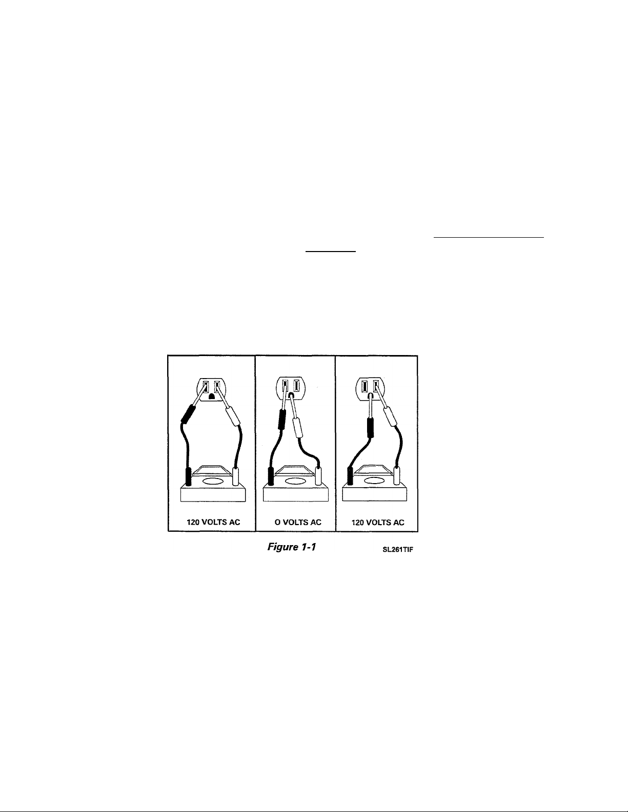
GROUNDING INSTRUCTIONS
The washer must be grounded. In the event
of a malfunction or breakdown, grounding will
reduce the risk of electrical shock by provid
ing a path of least resistance for electrical
current.
The washer is equipped with a power supply
cord which has a grounding conductor and
three-prong grounding plug. For proper
grounding, the three-prong grounding plug
must be plugged into an appropriate three-
prong grounded receptacle or outlet (see the
following figure). The receptacle must be
properly installed and grounded in accor
dance with the National Electrical Code and
all local codes and ordinances.
WARNING: Improper connection of the
grounding conductor or the three-prong
grounding plug of the power supply cord may
result in an electrical shock hazard. If there is
any doubt as to whether the washer is prop
erly grounded, have the installation checked
by a qualified electrician.
DO NOT MODIFY THE PLUG PROVIDED
WITH THE WASHER - If the plug will not fit
the outlet, have a proper outlet installed by a
qualified technician.
WARNING: For your
safety and to protect
the test equipment, be
sure that the wall out
let is properly polar
ized and grounded.
UNCRATING INSTRUCTIONS
NOTE: The following steps must be per
formed in the correct order to ease uncrating.
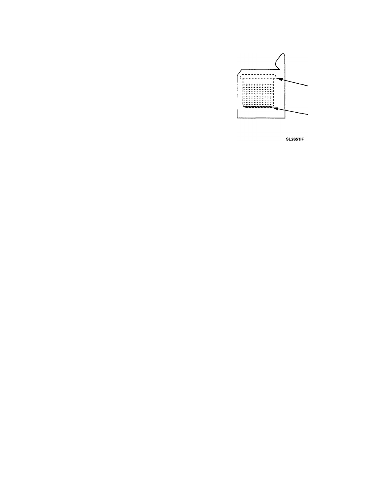
1. Remove the carton by cutting only marked
areas of the carton. CAUTION: Hoses are
connected to the washer.
2. Lift the carton and top cap assembly up
and clear of the washer. Carefully remove
any packaging materials from the outside
of the washer.
16009485-01
©1999 Maytag Appliances Sales Company
NOTE: Retain the corner posts for later use.
3. Remove tape and raise the washer lid; re
move the items shipped in the spin bas
ket. Save the literature for future refer
ence. Close lid and tape.
4. Position three (3) corner posts on the floor
near the rear base of the washer. Place
the remaining corner post on the floor
approximately two feet away. Carefully
lay the washer on its back, on top of the
corner posts.
Section 1. General Information
1-2
Page 11
DO NOT LOWER OR RAISE THE WASHER
BY THE CONTROL PANEL
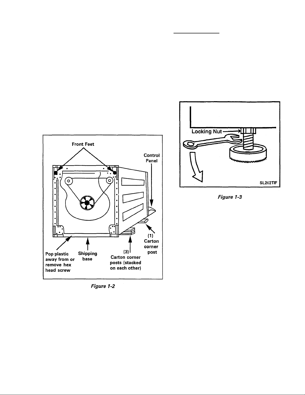
5. Remove the crate bottom from the washer.
Pop the plastic loose from the screw lo
cated between the back feet, or remove the
screw entirely with a screwdriver
(Figure
1-2). Pull the plastic base away from the
back feet. Grasping the plastic base on the
sides, pull down and toward you to release
the front feet from the slots and remove
the base. Discard the base (it can be re
cycled). RETURN THE WASHER TO THE
UPRIGHT POSITION.
Proceed as follows:
1. Place the washer as close to its final oper
ating location as possible.
2. Make sure rear feet move up and down
freely.
3. Place washer in final location.
INSTALLATION PROCEDURE
NOTE: Proper installation is the respon
sibility of the purchaser.
Service calls performed as a result of im
proper setup, adjustment and connection
are the responsibility of the installer.
4.
When the machine is in place, screw front
feet out of base against the floor until the
machine is level across the top front of
the washer.
5.
While holding foot still, turn the adjust
ing locknut clockwise until the nut is tight
ened firmly against base (Figure 1-3).
6.
Tilt machine forward until rear of cabi
net is approximately 4 inches off the floor.
Lower the machine back to the floor on
the rear feet. This operation causes the
rear stabilizing feet to conform to the con
tour of the floor and seat them solidly.
Push washer with hands on opposite
corners to check stability (Figure 1-4).
16009485-01
©1999 Maytag Appliances Sales Company
Section 1. General Information
1-3
Page 12
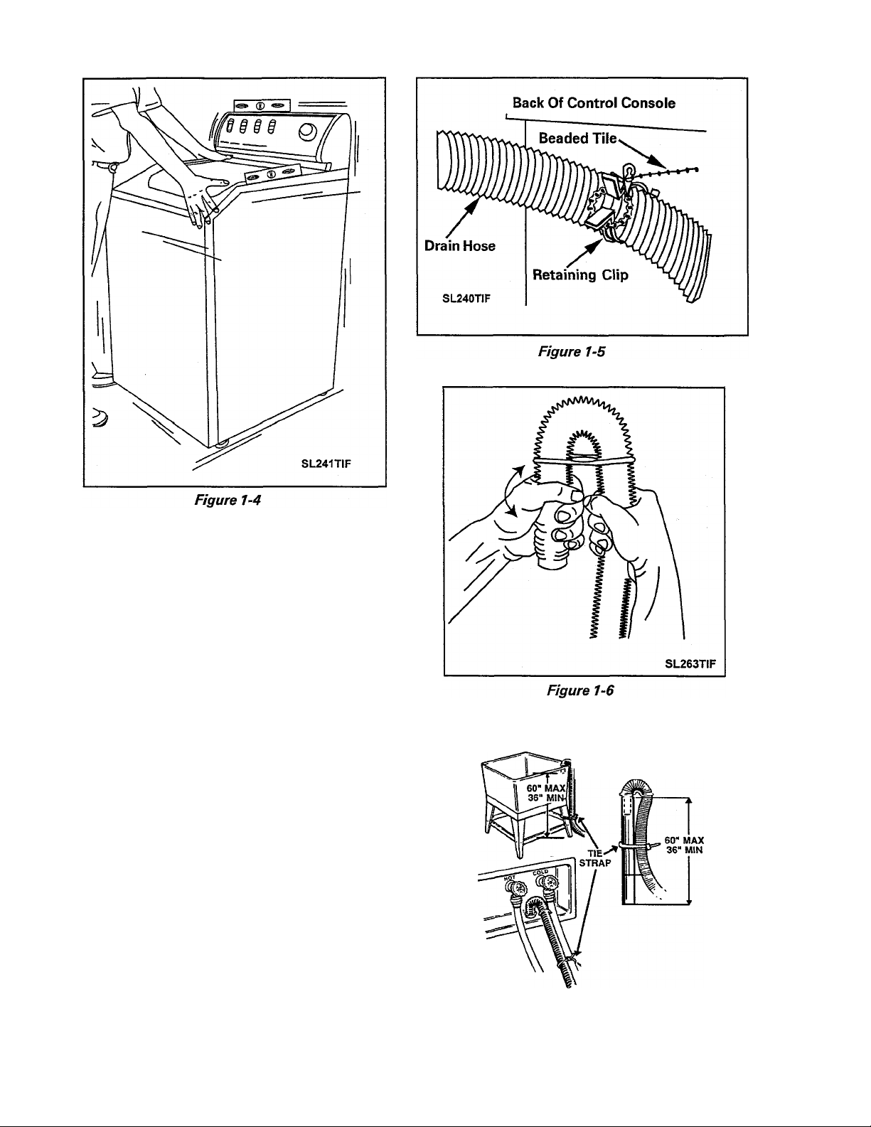
7. If the standpipe is less than 36" high, pull
the drain hose up vertically and snap the
hose into the retaining clip positioned on
the upper, rear cabinet wall (Figure 1-5).
8. Install gooseneck end of drain hose into
drain standpipe. Be sure the connection
is not airtight between the drain hose and
the standpipe. Standpipe must be at least
36" high. If the hose is twisted after it has
been placed into the standpipe, adjust the
end of the hose to remove the twist. To
remove the twist, turn the short end of
the hose while holding the base of the
hose stationary (Figure 1-6).
9. The drain hose should fit loosely in the
standpipe to prevent siphoning. (An anti
siphon valve and associated parts are
available from your dealer, part number
12001586.)
SERVICE
UNIT
LAUNDRY
TUB
STANDPIPE
NOTE: Be sure the drain hose is not
twisted or kinked.
16009485-01
©1999 Maytag Appliances Sales Company
SL297TIF
Figure 1-7
Section 1. General Information 1-4
Page 13
10. Secure the drain hose to the standpipe
or drain facility with the cable strap pro
vided. This will ensure the drain hose will
not fall out of the drain facility
(Figure 1-7).
SIDE VIEW OF WASHER
11. Connect inlet hoses to water supply us
ing screen washers at faucet connections,
with the domed plastic screen facing the
faucet (Figure 1-8). Tighten hose con
nections by hand until snug. Then, turn
another 2/3 of a turn with the pliers.
At Faucet Connection
0=^333
At Water Valve Connection
SL2S5T1F
Figure 1-8
12. With hoses attached to both the faucets
and the water valve, turn on the water and
check for leaks. Note the H and C desig
nations on the water vaive bracket for the
Hot and Cold hoses.
Tub
Water Level
Figure 1-9
FINAL INSTALLATION CHECK LIST
1. Have all installation requirements
been observed?
2. Have locknuts on front feet been
tightened?
3. Are there any kinks in the hoses?
4. Are any water leaks evident?
UNIQUE INSTALLATIONS
13. Plug the power cord into an outlet.
14. Start the washer in a spin cycle per oper
ating instructions to center basket.
15. Start the washer in a wash cycle per oper
ating instructions. Allow water to fill in
machine until it reaches the level of the
bottom row of holes in the wash basket.
Then, stop the washer by pushing on timer
knob.
16. If the water is not level with the bottom
row of holes all around the basket (Figure
1-9), readjust the leveling feet as required
to level. Remove the water by selecting a
spin cycle.
16009485-01
©1999 Maytag Appliances Sales Company
Painted/Sloped Basement Floors - Apply non
slip discs, part number 211692, to the floor di
rectly under the rubber feet of the washer.
Carpeted Floors - Apply carpet installation
discs, part number 204986.
Weak Floors - Install rear legs with plastic
grommets, part number 12001577, to be
inserted into base frame to substitute for
the self adjusting legs.
Cold Storage or installations - Installation in
any location subject to freezing temperatures
is not recommended. If the washer must be
installed in such a location, it should be thor
oughly drained after each use as follows:
Section 1. General Information
1-5
Page 14

• Turn off hot and cold water faucets.
• Disconnect both water inlet hoses at the
faucets. Lower them to the floor.
• With the service cord connected to the
electrical outlet, rotate the timer to the
normal start or fill position and pull timer
knob to start washer. Turn water tempera
ture selector switch to warm.
• When water stops draining from the hoses,
disconnect service cord.
• Lower the drain hose to the floor and al
low it to drain into a floor drain or shallow
pan.
In below-freezing temperatures, ice may form
in the "fill" flume and the pump. Raise the room
temperature and allow time for the ice to melt
before using the washer.
16009485-01
©1999 Maytag Appliances Sales Company
Section 1. General Information
1-6
Page 15
SPECIFICATIONS - WASHER
CAPACITY
ELECTRICAL
MOTOR
POWER USAGE
TRANSMISSION
WATER USAGE
HOSE LENGTHS
DIMENSIONS
3.2 Cubic Feet
120 Volts, 60 Hz; Requires 15 amp circuit breaker or fused electrical supply.
Power cord must be connected to a properly grounded and polarized outlet
1/2 H.P., reversible, 2 Speed, 115 volt, 60 cycle A.C.
Motor Input: During Agitation* -480 Watts Max. (Fast) 370 Watts Max.
(Slow)
During Pump Out* - 760 Watts (Fast) 510 Watts Max. (Slow)
Spin - 460 Watts (Fast) 340 Watts (Slow)
[‘Wattage readings taken with no clothes in spinner.]
Rack and pinion type, incorporating reduction gears
Water pressure should be 20 - 120 P.S.l. (1.06-8.44 kg/cm) at inlet hose
connection. (SEE PAGE 1-8 FOR MORE DETAILS)
Four foot inlet hoses with inlet washers attached to water valve.
Drain hose attached to pump and will accommodate 36" high drain stand
pipe.
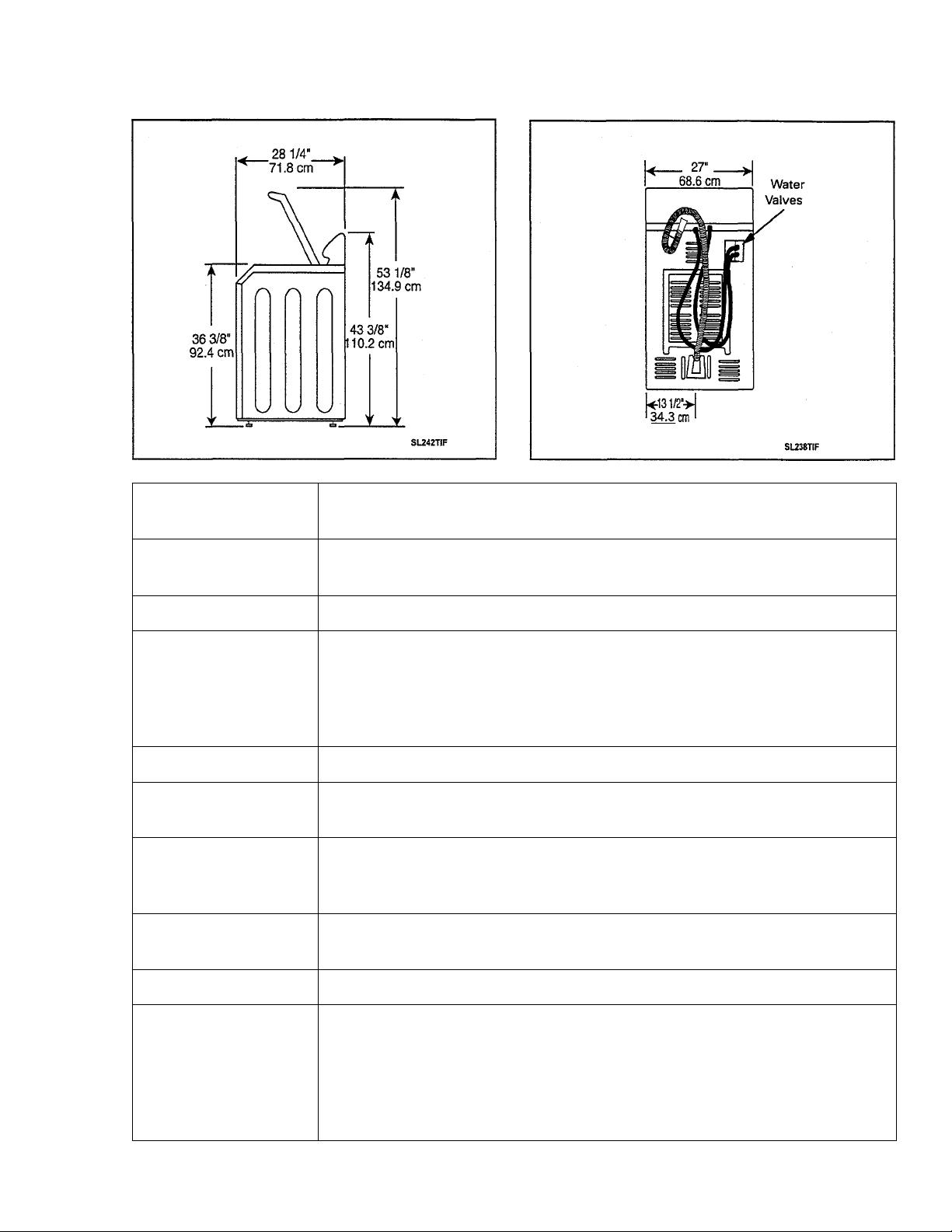
Cabinet Dimensions: 27" (68.58cm)W x 27 (68.58cm)D x 43 3/8" (110.2cm)H
Vi#’
WEIGHT (Approx.)
FINISH
16009485-01
Uncartoned 160 lb. (72.6 kg.) Approx. Crated 185 lb. (84 kg.) Approx.
Top Cover - Porcelain
Lid - Porcelain
Outer Tub - constructed entirely of polypropylene
Spin Basket - polypropylene
Cabinet - baked enamel
Base and other finished parts - baked primer
©1999 Maytag Appliances Sales Company
Section 1. General Information
1-7
Page 16

Setting
Mini
Medium
High
Super 23.3
^Allowable variations are plus or minus 1/2 inch.
Gallons
10.5
14.1
19.5
AGITATOR SPEED
*Depth
Inches
6"
8 1/2“ 5“
11" 7“
13 1/2“ 9 1/4"
Perforations
*Basket
3 1/2“
Regular Cycle 88 Oscillations per minute
Slow (Delicate) Cycle 57 Oscillations per minute 155 Degree Arc
155 Degree Arc
SPIN SPEED
Regular Cycle
Slow (Fine Wash) Cycle 410 R.RM.
TABLE 1-1. AMPERAGE CHART
WATER
CYCLE
Agitate-Regular Full Tub 10.4
Agitate-Slow Full Tub
Agitate-Regular
Spin-Regular
Spin-Slow DryTub
Pump Out-Regular
Pump Out-Slow Full Tub
LEVEL
DryTub 7.5
DryTub 10.2
Full Tub
620 R.RM.
♦AMPS
7.6
7.6
10.8
8.0
TABLE 1-3. WATTAGE CHART
♦WATTAGE
CYCLE
Agitate-Regular
Full Tub 610-640/670 (MAX.)
Agitate-Slow
Full Tub
Agitate-Regular
DryTub 460^70/480 (MAX.)
RANGE
370-400/420 (MAX.)
COMPONENTS
Timer Motor
Mixing Valve
Cold Solenoid
/Vof Solenoid
Drive Motor
16009485-01
TABLE 1-2. RESISTANCE CHART
♦RESISTANCE
(OHMS)
2360
500-1000
853
867
High Speed
Low Speed
Start 3.1
* These values can vary slightly.
1.3
2.3
©1999 Maytag Appliances Sales Company
Agitate-Slow
DryTub 350-360/370 (MAX.)
Pump Out-Regular
Pump Out-Slow
Spin-Regular
Full Tub
Spin-Slow
Full Tub 340
* These will vary with washer load and line voltage.
Section 1. General Information
760
510
460
1-8
Page 17

CYCLE CHARTS
COLORS
Function
Agitate
Agitate
Spin
Agitate
Spin w/Spray
SUPERWASH COLOF
Function
Agitate
Agitate Slow
Speed (Min.)
Fast
Slow
Fast
Slow
Fast
IS
Speed
Fast
Heavy
Option
Selected
Normal Light
Option
Selected
(Min.) (Min.)
9
9
6
6
9
Heavy
Option
Selected
(Min.)
18 12 9
0
3 0
9 9
6
6 6
9
Normal
Option
Selected
(Min.)
0
Option
Selected
6
9
Light
Option
Selected
(Min.)
0
Spin Fast
Agitate
Spin w/Spray Fast
Slow
6
6
9
6
6
9
WHITES
Heavy
Option Option
Selected Selected
Function
Agitate
Agitate Slow
Spin w/Spray Fast
Agitate Fast 6 6 6
Spin
Speed (Min.)
Fast
Fast
12 6
9
6 6
9
Normal Light
Option
Selected
(Min.) (Min.)
9 9
9
6
6
9
0
6
9
16009485-01
©1999 Maytag Appliances Sales Company
Section 1. General Information
1-9
Page 18

SUPERWASH WHITES
Heavy
Option
Selected
Function
Agitate
Speed
Fast
(Min.)
Agitate Slow 0
Spin w/Spray Fast 6
Agitate Fast 6
Spin
Fast
DELICATES
Heavy
Option
Selected
Function Speed
Agitate
Slow
(Min.)
21
9
0
Normal
Option
Selected
(Min.)
15
0 0
6 6
6 6
9
Normal
Option
Selected
(Min.)
3 0
Light
Option
Selected
(Min.)
9
9
Light
Option
Selected
(Min.)
Soak
Not
Applicable
Agitate Slow
Soak Not
Applicable
Agitate Slow
Spin w/Spray Slow
Agitate Slow
Spin
Slow
0
0
0
0
0
0
0
3 0
3 3
3 3
3 3
6
3 3
6 6
6
16009485-01
©1999 Maytag Appliances Sales Company
Section 1. General Information
1-10
Page 19

SUPERWASH DELICATES
Heavy
Option
Selected
Function
Agitate
Speed
Fast
(Min.)
Not
Soak
Agitate
Applicable 0
Slow
Not
Soak
Agitate
Applicable
Slow
Spin w/Spray Slow 0
Agitate Slow 0
Spin
Slow
Normal
Option
Selected
(Min.)
0
0 3
0 3
0
0
Light
Option
Selected
(Min.)
3
0
3 0
3
3
3 3
6 6
3 3
6 6
16009485-01
©1999 Maytag Appliances Sales Company
Section 1. General Information
1-11
Page 20
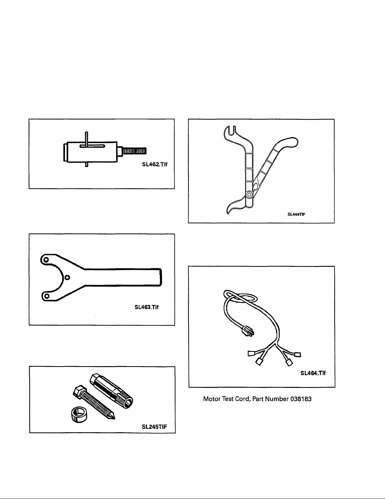
SPECIAL TOOLS
All special tools are manufactured by Robinaire with the exception of the 35-2442 Brake
Removal Tool and 35-2968 Spanner Wrench - Basket Hub. These tools are privately manu
factured for and stocked by Customer Service.
NOTE: The tools listed below can be ordered from any authorized Customer Service parts
distributor.
Brake Removal Tool, Part Number LA-2004
Spanner Wrench-Basket Hub, Part Number 35-2968
Spring Tool, Part Number 22002922
Seal Removal Tool, Part Number 2000021
16009485-01
©1999 Maytag Appliances Sales Company
Section 1. General Information 1-12
Page 21
SECTION 2. OUTLINE OF MECHANICAL OPERATION
GENERAL INFORMATION
NOTE: The rotation directions, stated in this
outiine, view the component from its ouiiev end.
The washer utilizes a reversible type motor
which turns clockwise during the agitate
cycle and counterclockwise during the spin
cycle.
A single belt is used to transmit power from
the motor pulley to the drive and pump pul
leys.
CLUTCH ASSEMBLY
The transmission drive pulley, which drives the
transmission drive shaft and hub assembly,
and the pump pulley which drives the pump
impeller, are in operation whenever the mo
tor is running.
The transmission assembly converts the
power from the motor to either drive the agi
tator or spin the basket. The direction the
clutch assembly rotates determines which
action takes place.
Washer-Thrust Hub
Figure 2-1
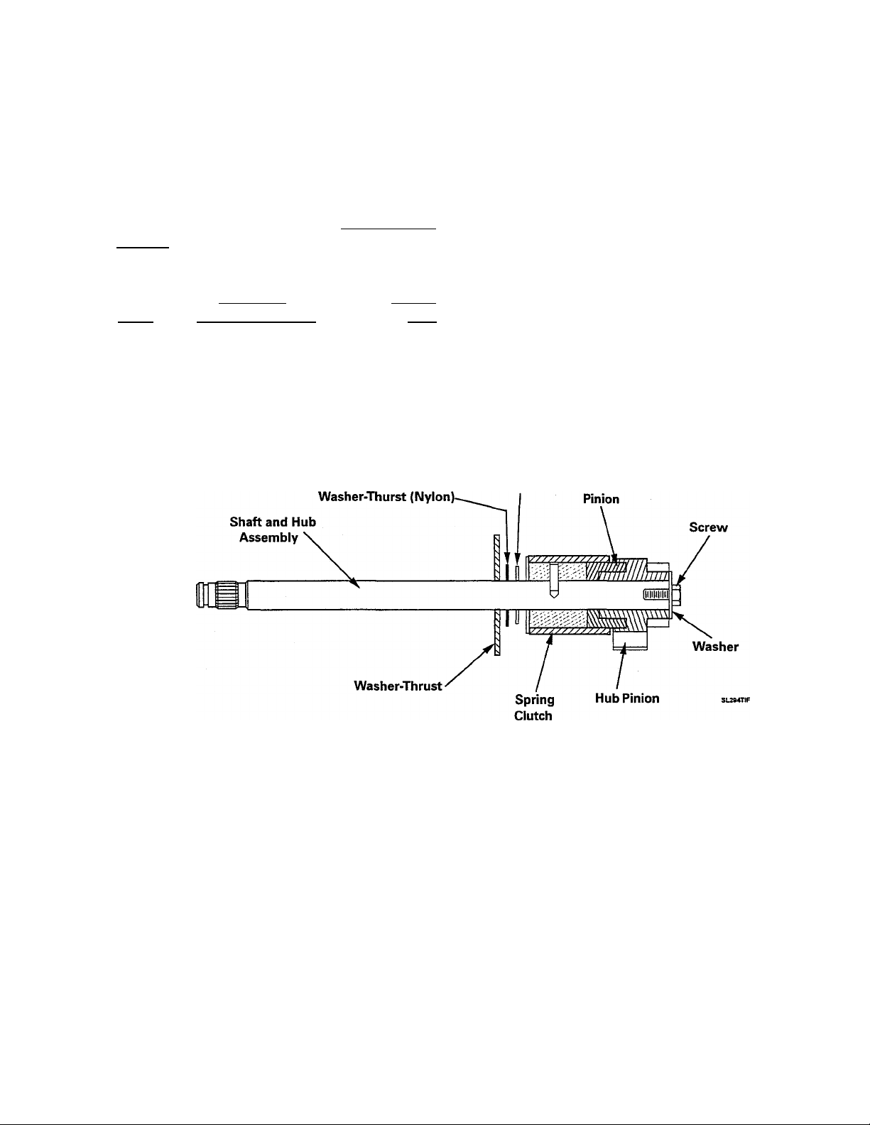
CLUTCH ASSEMBLY
The clutch assembly (Figure 2-1) consists of
the drive shaft and hub assembly, clutch
spring, and input pinion with gear lock assem
bly. The gear lock mechanism is part of the
input pinion. The drive shaft serves only as a
bearing surface for the drive pinion to revolve
on. No direct drive is imparted from the shaft
directly to the pinion. The inside diameter of
the clutch spring is designed so that when the
drive shaft is driven in a clockwise direction.
16009485-01
©1999 Maytag Appliances Sales Company
the clutch spring tightens on the two hubs and
becomes a positive link between them. When
the drive shaft hub runs counterclockwise, the
clutch spring relaxes in an override situation.
While in override, or relaxed position, the
clutch spring still maintains a drive link be
tween the two hubs. The override tension, or
torque, is used to drive the spin basket. The
gear lock mechanism consists of two "wings"
that project out from the input pinion.
Section 2. Operation
2-1
Page 22
Transmission
' Housing
Assembly
Lower Bearing
And Housing —
Assembly
Oil Seal ■
Suspension
Housing
Brake Spring
Retainer
Retaining
Ring
Drive Tube
Splines
Drive Shaft
Splines
Thrust Bearing
Washer (Curved)
Outer Edge
Turned Up
I
I
I Drive Pulley
I Assembly
Lower Cam ■
I
Spacer
Washer (thin)
~ Upper Race
)>^Washer (thick)
Lower Race
Washer (thin)
Thrust
Brake Rotor
And Lining
Assembly
Brake
Stator
Figure 2-2
Retaining
Ring
-Thrust
Washer
■Dust Cap
16009485-01
©1999 Maytag Appliances Sales Company
Section 2. Operation
2-2
Page 23

When the drive pinion rotates in a clockwise
direction, the gear lock mechanism exerts no
force on the input pinion. When the input pin
ion starts to revolve counterclockwise the
"wings" drop into dents in the lower housing
preventing the pinion from turning.
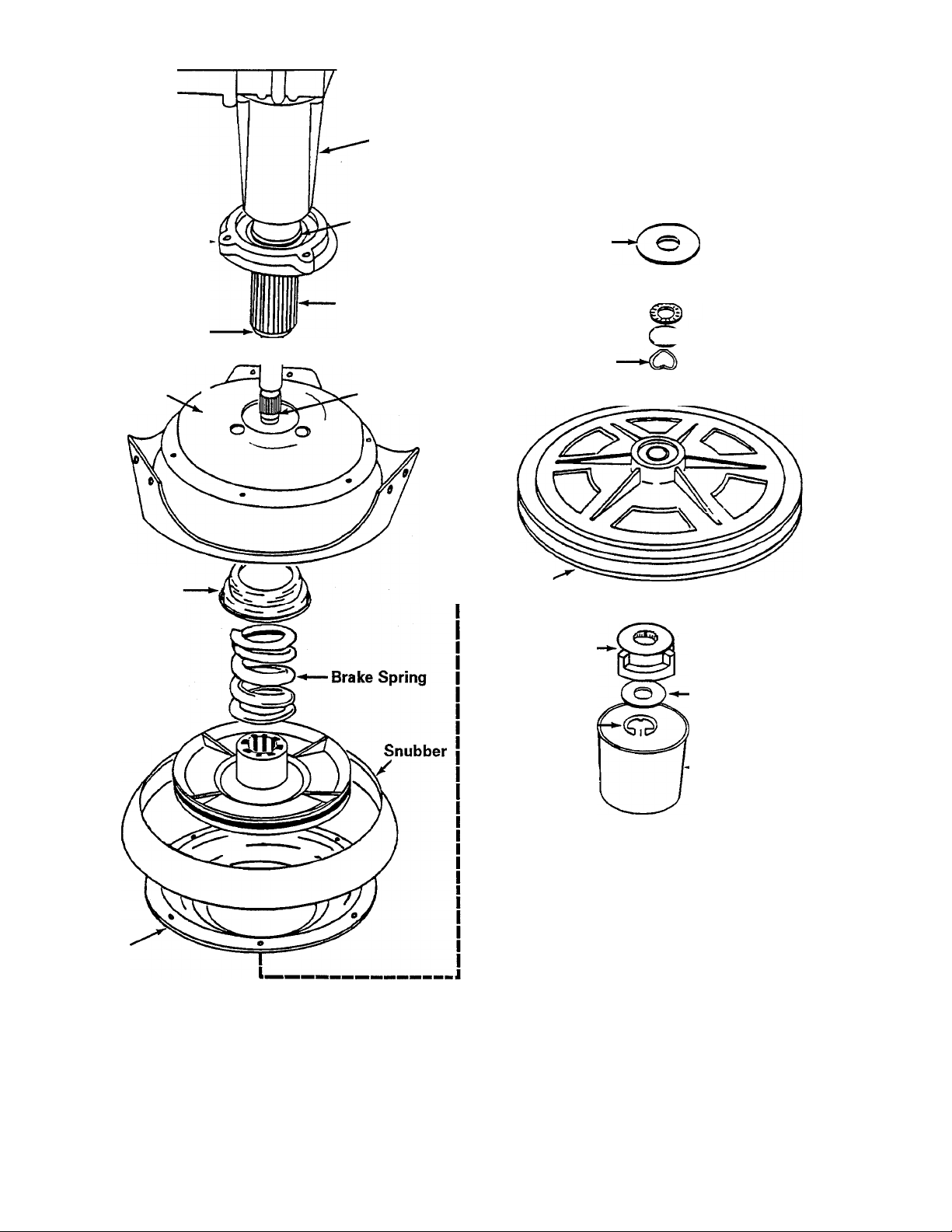
DRIVE PULLEY AND CAMS
OPERATION: AGITATION
When the drive pulley rotates CLOCKWISE,
the upper and lower cams are designed to nest
together which allows the drive pulley to re
main in position on the drive shaft. The brake
remains engaged and the drive pulley will turn
the lower cam and drive the shaft to cause
the transmission to agitate.
The drive pulley and cam is located below
the brake assembly on the drive shaft
(Figure 2-2).
All models are equipped with a plastic drive
pulley which has the upper cam molded
onto the bottom of the hub. The purpose of
the pulley and cam arrangement is to drive
the clutch assembly during the agitate and
spin cycle, and to disengage the brake
assembly during the spin cycle.
The drive pulley slips over the drive shaft and
rests against a series of washers, a thrust
bearing, and a large washer type spacer. The
spacer locates against the bottom of the
brake rotor and lining assembly (See the
illustration on page 7-6).
The lower cam slips over the end of the drive
shaft where splines formed in the cam en
gage with mating splines on the drive shaft
end. This imparts a direct drive from the cam
to the drive shaft.
A shoulder molded on the bottom of the
pulley hub engages “dogs" formed on the
sides of the lower cam, and will drive it and
the drive shaft in either direction.
The agitation is due to the clockwise (agitate)
rotation of the drive shaft and the hub assem
bly as it is transmitted to the input pinion by
the clutch spring. The input pinion meshes
with the dual cluster gears which, in turn mesh
with the dual crank gears (Figure 2-3). The
circular motion of the dual crank gears are con
verted to the oscillating action of the agitator
shaft by the dual rack gears. The rack gears
have a stud that drops into the crank gears.
These rack gears are contained by a rack car
rier. Any tendency of the transmission to turn,
or "creep," is prevented by the engaged brake
assembly located on the under side of the
suspension housing.
OPERATION: SPIN
When the drive pulley rotates COUNTER
CLOCKWISE, the upper cam and pulley ride
up the lower cam approximately 3/16 of an
inch before the driving shoulders on the pul
ley hub engage the "dogs" on the lower cam.
This causes the top of the pulley hub to push
against the spacer which compresses the
brake spring and lifts the brake rotor and lin
ing assembly off the brake stator. The brake
is disengaged and the pulley will turn the lower
cam and drive shaft to cause the transmission
to spin.
A washer and retaining ring secure the pul
ley and cam on the drive shaft. A plastic dust
cap snaps to the underside of the pulley to
keep the cam surfaces clean.
16009485-01
©1999 Maytag Appliances Sales Company
A nylon cam, along with a special drive pul
ley, provides a cam action which raises the
drive pulley during the counterclockwise
(spin) rotation of the motor (Figure 2-2). As
the drive pulley hub moves up, it compresses
a brake spring and lifts the brake rotor and
lining assembly, disengaging it from the sta
tor. The transmission is now free to spin.
Section 2. Operation
2-3
Page 24

The counterclockwise rotation of the drive
shaft and hub assembly causes the clutch
spring to relax into an override position. The
clutch spring still exerts a driving force to the
input pinion even when it is in the override
position. As this driving force of torque starts
to turn the input pinion in a counterclockwise
direction, it causes the "wings" of the gear lock
mechanism to drop into dents on the lower
housing. This prevents the input pinion from
revolving in the counterclockwise direction.
Therefore, the torque being delivered by the
clutch spring is exerted against the transmis
sion housing, causing the entire assembly to
rotate. The washer basket is mounted to the
basket drive hub which is secured to the trans
mission cover assembly, and revolves as part
of the transmission. In this direction, the
pump assembly will drain the water out of the
unit.
16009485-01
©1999 Maytag Appliances Sales Company
Section 2. Operation 2-4
Page 25
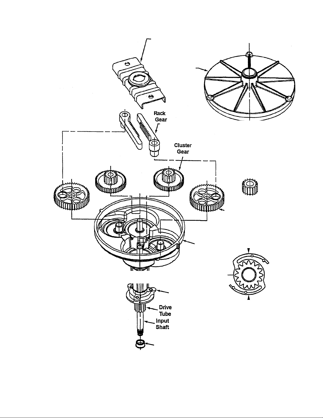
Rack Gear
Carrier
Transmission
Cover
Agitator
"shaft
r
Output
^ Pinion
Lower
Seal
Bearing
Housing
Transmission
Housing
Input Pinion
Crank
Gear
—Wings
16009485-01
Figure 2-3
©1999 Maytag Appliances Sales Company
Section 2. Operation 2-5
Page 26

16009485-01
©1999 Maytag Appliances Sales Company
Section 2. Operation 2-6
Page 27
SECTION 3. EXPLODED VIEW OF COMPONENTS
16009485-01
Section 3. Exploded View Of Components 3-1
©1999 Maytag Appliances Sales Company
Page 28
:y
16009485-01
SL315TIF
Section 3. Exploded View Of Components 3-2
©1999 Maytag Appliances Sales Company
Page 29
SECTION 4. CABINET ASSEMBLY COMPONENTS
A
WARNING
Warning - Always shut
off electrical power to the
washer before beginning
any service repair proce
dures.
CONTROL PANEL ASSEMBLY REMOVAL
1. Disconnect power to the unit.
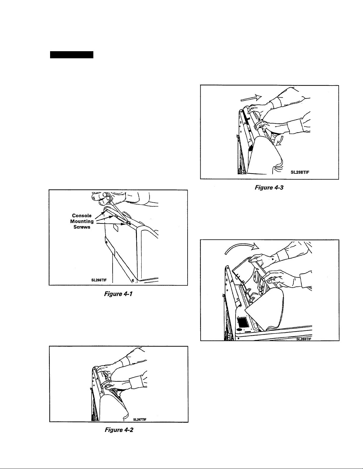
2, Remove the three screws securing the
console rear cover plate across the rear
top edge of the console (Figure 4-7).
5. Push the bottom of the console toward the
back panel to disengage the six locking
feet from the top cover (Figure 4-3).
6. Carefully lift and roil the console forward
onto the top cover. You now have access
to the console components and wiring
(Figure 4-4).
3. Lay a drop cloth across the top cover of
the washer.
4. Grasp the top of the console and gently
rock the top forward (Figure 4-2).
16009485-01
©1999 Maytag Appliances Sales Company
Figure 4-4
To Reinstall: Roll the console back into an
upright position, engaging the locking feet
into the slots in the top cover. Replace the
three screws to attach console back to rear
panel.
Section 4. Cabinet Assembly Components 4-1
Page 30
VERTICAL SWITCHES (Push Button)
REMOVAL
1. Depress the tab at the top of the switch
with a screwdriver to disengage the tab
from the console. Pivot the switch away
from the console to remove (Figure 4-5).
REPLACEMENT
1. Align the rib on the bottom of the switch
with the slot in the console. Pivot the
switch up into the console until the tab en
gages the console securely. Check that the
locating tabs on either side of the switch's
lower alignment rib are in position to prop
erly center and lock the switch into the
lower part of the switch opening.
3. Disengage the console assembly from the
top cover and roll forward (See Console
Removal).
4. Remove timer mounting screws under the
timer knob.
5. Lift the timer away from the console.
TIMER REMOVAL - All MAV Models Except
MAV8500
1. Disconnect power to the unit.
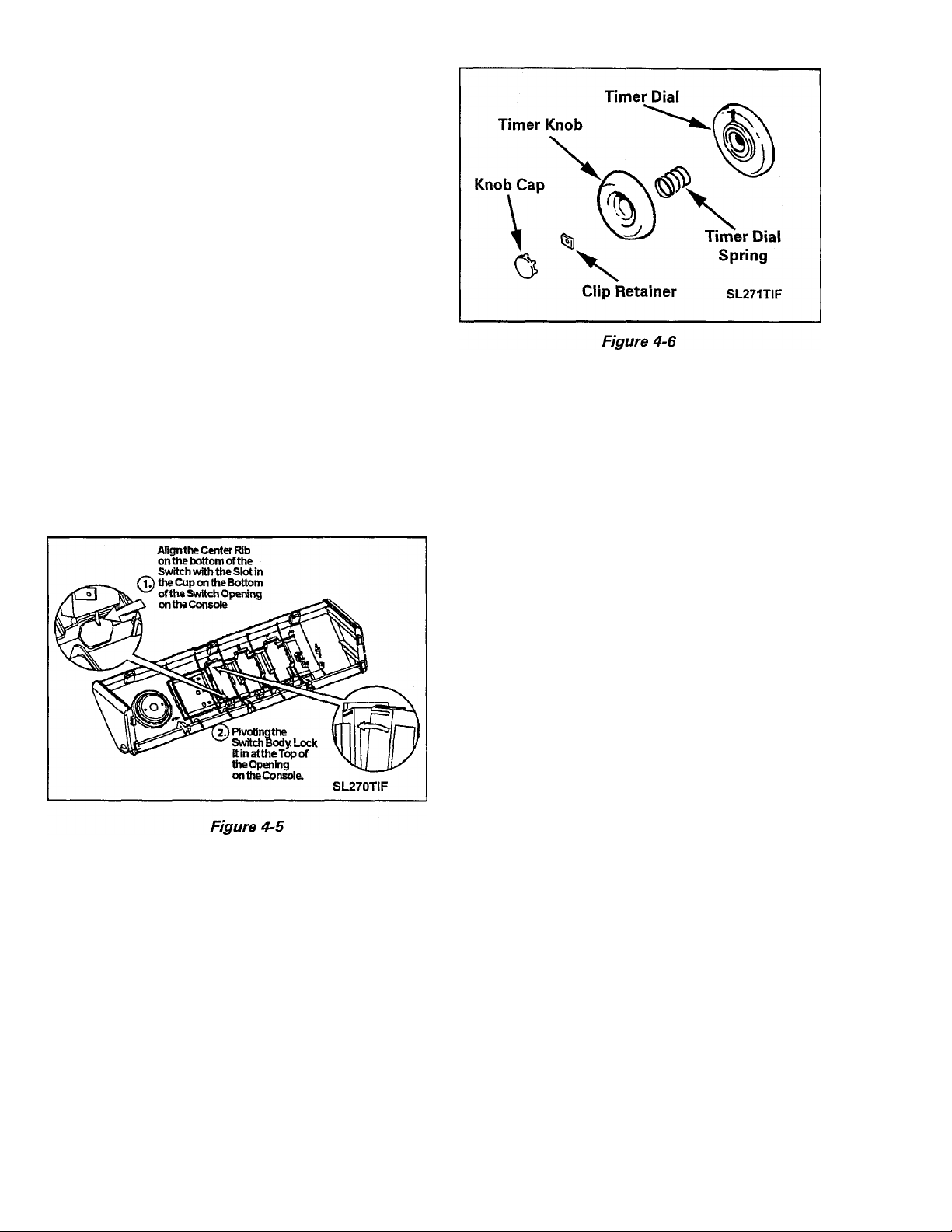
2. Carefully lift the timer knob cap from the
timer knob and pry the clip retainer from
the timer shaft. Lift the dial and knob off
the timer shaft by pulling away from the
face of the control console (Figure 4-6).
REPLACEMENT
1. Reverse steps 1 through 5.
TIMER REMOVAL - MAV8500 Models
1. Disconnect power to the unit.
2. Remove the knob cap.
3. Gently pry the locking pin up and lift the
timer knob off the dial skirt.
4. Lift the dial skirt off the timer shaft
(Figure 4-7).
16009485-01
Section 4. Cabinet Assembly Components 4_2
©1999 Maytag Appliances Sales Company
Page 31

AUTOMATIC TEMPERATURE CONTROL BOARD
REMOVAL
1. Disengage the console assembly from the
top cover and roll forward (See Console
Removal).
2. Remove wire harness from control board.
3. Squeeze the locking tabs together
(Figure 4-9).
4. Slide the control board and bracket away
from the timer motor to unhook the bracket
from the timer rear face plate. Mounting
hooks on the bracket engage with the edge
of the timer rear face plate.
FOR ALL MAV8500 MODELS
1. Remove board mounting screw, and
bracket mounting screw.
2. See Figure 4-8 for additional assistance.
16009485-01
©1999 Maytag Appliances Sales Company
Section 4. Cabinet Assembly Components 4-3
Page 32

TOP COVER ASSEMBLY
The top cover assembly consists of the top
cover, washer lid assembly, lid switch and
bracket, water inlet flume, bleach dispenser,
and the control panel assembly.
The assembly is mounted to the cabinet with
two (2) steel hinges which are attached to the
upper cabinet. These hinges engage into
hinge slots located in the back edge of the
cabinet which allows the top cover to be raised
for servicing.
Two (2) slots pierced into the front flange of
the top assembly align with two (2) locating
plastic shipping stops to center the top cover
to the cabinet. Two (2) spring clips engage
the top cover flange and secure the top as
sembly to the cabinet front.
NOTE: The locating pins and top dips are
mounted to the front pane! flange on all the
models (Figure 4-10).
Raising the top will allow access to:
3. Raise the top cover assembly and remove
the flume inlet hose from the water valve.
4. Lower the top and remove the control
panel rear shield.
5. Disconnect the pressure switch hose and
all necessary wiring. Feed the hose and
wiring through their respective top holes.
6. While pulling forward, slightly raise the top
cover assembly forward and remove.
• Flume and Inlet Hose
• Lid Switch Actuator
• Air Dome Hose Connection
• Water Inlet Valve Wiring
• Spin Basket Assembly
• Outer Tub Assembly
REMOVAL
1. Disconnect power to the unit.
2. To raise the top assembly, insert a thinbladed tool (such as a putty knife) between
the front panel and top assembly approxi
mately three (3) inches in from each cor
ner. While raising the top assembly, de
press each spring clip (Figure 4-10).
STANDARD LID ASSEMBLY
The washer and lid assembly consists of the
lid, mounting hinges, plastic lid switch cam
(switch actuator) and condensation seal with
bumpers. The assembly is secured to the top
panel by the two mounting hinges.
When the washer lid is lowered, the plastic lid
switch cam protrudes through a slot in the rear
of the top cover and depresses a plunger that
actuates the lid switch (Figure 4-11).
16009485-01
Section 4. Cabinet Assembly Components
©1999 Maytag Appliances Sales Company
4-4
Page 33

REMOVAL
1. Lift the washer lid.
2. Locate the left hinge and lift the locking
tab in the center of the hinge from the lo
cating hole in rear edge of the lid
(Figure 4-12).
3. Gently pry the hinge toward the center of
the lid. This will draw the pin of the hinge
out of the bushing in the top cover
(Figure 4-12).
4. With the left hinge removed, grasp the lid
and pull the lid away from the right hand
bushing in the top cover.
REPLACEMENT
1. Reverse steps 1 through 4.
30 DAY DETERGENT DISPENSER (Optional Accessory)
The Dosing Lid Assembly consists of the de
tergent reservoir, dispenser valve assembly,
cap and twist locks.
The reservoir stores liquid detergent and will
dispense the detergent directly into the spin
basket when the actuator is manually de
pressed. The detergent reservoir is secured
into the lid by four twist locks.
Removal of Reservoir
1. Turn each of the twist locks on the face of
the detergent reservoir 1/4 turn counter
clockwise (Figure 4-13).
2. Pull the bottom of the reservoir away from
the lid and unhook the top of the reservoir
from under the lip of the lid.
Removal of Valve Assembly
1. Locate the locking clip below the dispens
ing button (Figure 4-14).
2. Depress the dispensing button while slid
ing the retaining clip down. This will re
lease the plunger and dispensing button
and allow removal.
16009485-01 Section 4. Cabinet Assembly Components 4-5
©1999 Maytag Appliances Sales Company
Page 34

Figure 4-13
Warning: The spring in the valve assembly
is compressed and may fly out of the dis
penser. Depressing the plunger button
during dip removal will prevent this from
occurring.
Slide the left retainer toward the center of
the lid and remove from behind the lid
flange (Figure 4-15).
With the left retainer removed, grasp the
lid vertically and rotate the torsion rod in
a clockwise direction away from the right
hand plastic bushing in the top cover.
TORSION ROD ASSEMBLY
The torsion rod assembly acts as a counter
balance when liquid detergent is in the dis
penser. This allows for easier opening and
closing of the washer lid.
REMOVAL
1. Lift the washer lid and remove the deter
gent reservoir.
2. Remove the center support from the tor
sion rod by rolling the support toward you.
DETERGENT DISPENSING
Figure 4-16
1. After initially filling the reservoir of the dis
penser, lower the lid to fill the dispensing
chamber on the left side of the dispenser.
16009485-01
Section 4. Cabinet Assembly Components 4_0
©1999 Maytag Appliances Sales Company
Page 35

2. Position the cap of the detergent bottle be
ing used under the spout of the dispenser.
3. Press and hold the button and dispense liq
uid into the cup until the desired amount
has dispensed.
4. Slide the plastic indicator down the sight
window until even with the detergent
shown.
5. The next time the lid is lowered and raised,
the sight window will fill with liquid deter
gent. By depressing the button until the
level in the sight window is even with the
indicator, will provide uniform dispensing
of detergent brand being used.
NOTE: Empty dispenser completely before
refilling. Do not mix different detergents.
2. Remove the dispenser valve assembly and
rinse with warm water fSee Removal of
Valve Assembly Page 4-6).
3. Fill the dispenser with hot or warm water
and gently tilt the dispenser forward and
back to flush the water around inside the
dispenser.
4. Turn the dispenser vertically so the fill cap
is facing up and remove the cap. Pour the
contents out and repeat the process until
dispenser is flushed. NOTE:
Water will
flow out of the dispenser valve area.
5. Reinstall the dispensing valve assembly
into the reservoir. While depressing the
button, replace the clip onto the valve
assembly.
6. Reinstall the reservoir into the lid and se
cure the twist locks.
Figure 4-17
CLEANING THE DISPENSER
Mixing different liquid detergents in the res
ervoir can cause the detergent to clump and
clog the dispenser outlet. In which case, clean
ing out the reservoir is necessary.
1. Remove the dispenser from the lid (See
Removal of Reservoir Page 4-6).
7. Close and open the lid.
8. Press the "PUSH" button (plunger) to re
lease any remaining water/detergent. Re
peat steps 7 & 8 until no more water can
be drained from the dispenser. It is nor
mal for a small amount of water to remain
in the dispenser after cleaning.
9. Refill the dispenser with liquid detergent.
The reservoir will hold 100 fluid ounces at
one time.
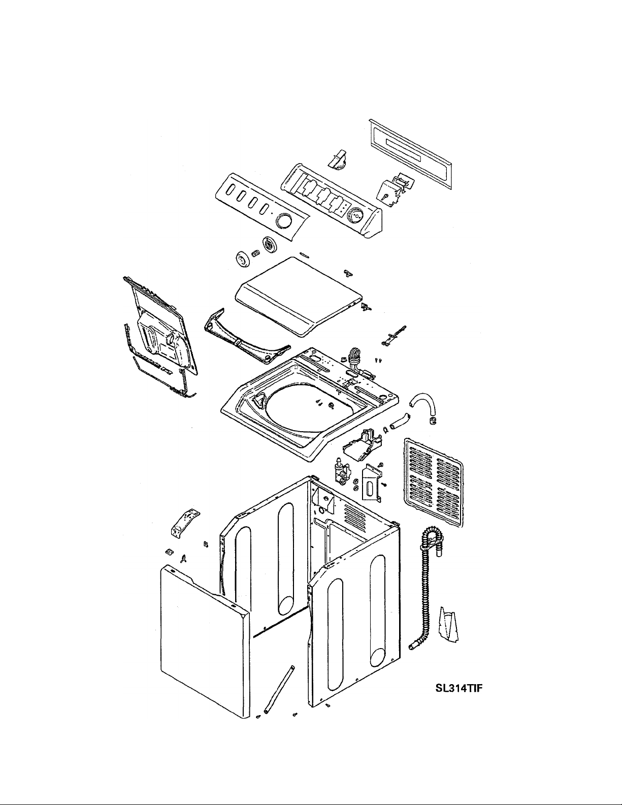
FRONT PANEL
The front panel is attached to the cabinet side
flanges via screws at the top and secured at
the bottom with base mounting clips. Locat
ing tabs on the front panel flanges position
the top cover for assembly (Figure 4-18).
The front panel provides mounting for the lo
cating tabs and top clips. A plastic support
brace is wedged in the center of the panel for
support.
16009485-01
©1999 Maytag Appliances Sales Company
Section 4. Cabinet Assembly Components 4-7
Page 36

Front panel removal will allow access to the:
Motor
Motor Mount
Motor Wiring
Motor Pivot Spring
Suspension Springs
Tub Brace
Pump
Remove the two 5/16" hex/cross head
screws securing the front panel to the up
per front corner braces of the cabinet.
(Figure 4-19 & 4-20)
Move top edge of front panel away from
4.
cabinet while lifting. This will disengage
the bottom of front panel from base clips.
REPLACEMENT
1. Reverse above steps.
REMOVAL
1. Disconnect power to the unit.
2. Insert a thin-bladed tool between the front
panel and the top cover assembly, approxi
mately three (3) inches in from each cor
ner. While lifting up on the top cover as
sembly, press the blade against the wire
clips, one side at a time to disengage them.
Lift the top cover up to a stationary
position.
16009485-01
©1999 Maytag Appliances Sales Company
Figure 4-19
REAR ACCESS PANEL
Removal of the access panel, gains access
to the rear inside components of the washer.
Panel removal will allow access to:
• Stabilizer Assembly
• Rear and Side Suspension Springs
• Tub Braces
REMOVAL
1. Remove the four screws surrounding
the access panel (Figure 4-20).
Section 4. Cabinet Assembly Components 4.3
Page 37

CABINET BODY ASSEMBLY
The cabinet provides mounting for the front
panel, rear access panel, top cover assembly,
water valve and the power cord.
9. Remove the eleven (11) screws that secure
the cabinet body to the perimeter of the
base.
10. Open the front of the cabinet body slightly
and push if off the rear of the base frame.
BASE ASSEMBLY
The base assembly, which serves as a support
for the entire wash unit, is constructed of
heavy gauge metal that has been flanged and
embossed for strength.
There is a spherical configuration on the lower
end of the brake/transmission/tub assembly.
This spherical shape rides on the raised dome
like area in the center of the base. The mount
ing is similar to a ball joint and allows the hous
ing to move freely in all directions
(Figure 4-21).
The cabinet is attached to the perimeter of the
base with eleven (11) screws.
REMOVAL
1. Disconnect power to the unit.
2. Remove the top cover (See TOP COVER
REMOVAL - Page 4-3).
3. Remove the front panel (See FRONT PANEL
REMOVAL - Page 4-8).
4. Remove the power cord.
5. Remove rear access panel and drain hose
cover.
6. Remove water valve and bracket.
7. Remove wiring clips and clamps from
inner cabinet rear.
The base assembly also provides mounting for
the pump assembly, motor and plate assem
bly, suspension springs, front panel clips, and
the stabilizer assembly.
The cabinet is secured to the base with screws
and positioned foam pads to prevent vibra
tion or noise transfer. The cabinet does not
support any of the wash unit's weight.
BASE REPLACEMENT
1. Disconnect power to the unit.
2. Tip unit back and remove the drive belt.
3. Remove the drain hose cover from the
cabinet rear and disconnect the discharge
hose from the pump outlet.
4. Remove the top cover (See TOP COVER
REMOVAL - Page 4-3).
8. Remove front cross braces and screws.
16009485-01
©1999 Maytag Appliances Sales Company
5. Remove the front panel (See FRONT
PANEL REMOVAL - Page 4-7).
Section 4. Cabinet Assembly Components 4-9
Page 38

6. Disconnect lower wiring from the cabinet
rear (water mixing valve, power cord, etc.)
and remove pressure switch hose from tub
air bell.
7. Remove the screws attaching the cabinet
to the base.
8. Remove lower screws on cross braces.
9. Push the front of the cabinet slightly back
and carefully push or pull it off the rear of
the base assembly.
11. Remove motor mounting screws, ground
wire and wiring clips from base. Lift the
motor and plate assembly from the base.
12. Remove the suspension springs (See
SPRING REMOVAL, Page 6-2 thru 6-3).
13. Remove the stabilizer assembly from
the base assembly, as detailed later in
this section.
14. Transfer the remaining hardware from
the defective base to the replacement.
10. Disconnect the pump hose from the tub
outlet and remove the pump assembly and
hose from the base.
16009485-01
©1999 Maytag Appliances Sales Company
15. Installation is a reversal of the above
procedure.
Section 4. Cabinet Assembly Components 4-10
Page 39

STABILIZER ASSEMBLY
The stabilizer assembly consists of the
stabilizer bar assembly, two (2) stabilizer
brackets, two (2) self stabilizing feet, and
two (2) foot pins. It is mounted on the top
rear of the base assembly.
The stabilizer assembly allows the base
assembly to rest solidly and firmly against
the floor, even if the floor is unlevel. The
solidity of the base to the floor keeps the
washer from rocking back and forth or
“walking" during
operation.
As the name implies, the stabilizer only
stabilizes the unit; it does not level it. Any
leveling that is required must be done
with the front adjusting (leveling) legs.
In rare cases where the floor is so uneven
that it is beyond the stabilizing limit of the
assembly (+ or - 5/8"), It may be neces
sary to remove the stabilizer assembly
and install two (2) rear adjustable feet.
Two (2) threaded holes have been pro
vided in the rear corners of the base for
this situation. A kit, part number
12001577 is available.
REMOVAL
1. Disconnect power to the unit.
2. Remove the access panel from the
cabinet rear.
3. Tip or lay washer down, either forward
or on the side. Remove the screws
from the underside of the base that
attaches the stabilizer assembly to the
rear of the base (Figure 4-21).
4. Remove the stabilizer assembly
through the rear access panel.
5. To disassemble the stabilizer assembly
after removal, drive the two (2) foot
pins out of the feet and brackets.
NOTE: in order for the stabilizer assem
bly to operate properly, a thin coating of
grease must be applied over the entire
length of the four (4) pin guides as well
as the foot holes in the bracket (Figure 4-
11).
16010280
(16009485-02)
SECTION 4. Cabinet Assembly Components
©2000 Maytag Appliances Sales Company
4-11
Page 40

TOP COVER TO CABINET HINGE
Some models will have a plastic hinge
assembly holding the main top to the
cabinet. (Figure 4-1)
Figure 4-1
The hinge assembly is removed from the
unit by lifting the main top about 2 inches
and sliding it forward. The hinge is then
removed by pushing up and out on the
lower tab and lifting the hinge up to
release it from the cabinet. (Figure 4-2)
Lift up and push out on hinge tab to
release hinge from cabinet
Figure 4-2
16010280
(16009485-02)
SECTION 4, Cabinet Assembly Components
©2000 Maytag Appliances Sales Company
4-12
Page 41

SECTION 5. WATER ■ RELATED COMPONENTS
A
WARNING
WATER MIXING VALVE
Warning - Always shut
off electrical power to
the washer before begin
ning any service repair
procedures.
The water mixing valve is located inside the
left rear cabinet area, when viewing from the
front. It is secured by two (2) screws inserted
through the valve bracket and into the cabi
net. The hot and cold water supply inlet hoses
are attached to the nozzles of the water valve.
The mixing valve will allow hot or cold water,
or a mixture of the two as called for by the
27"
68.6 cm
Water
Valves
control circuitry, to enter the machine through
the inlet hose and inlet flume.
Usually, the temperature of the warm water
entering the machine will be about halfway
between the cold and hot water temperatures
delivered to the valve. This will occur when
the flow rate of both are equal.
Inlet Hoses
16009485-01
<■131/2">1
34.3" cm '
SL232TIF
SL238TIF
Figure 5-1
Section 5. Water Related Components 5-1
©1999 Maytag Appliances Sales Company
Page 42

WATER INLET FLUME
HOSES
The molded plastic water inlet flume consists
of an upper and lower section that has been
snap-locked together.
The flume is located on the rear underside of
the washer top assembly. The flume fits flush
with the top opening and is secured to the top
by one mounting screw, accessed through the
control console. An inlet hose from the wa
ter mixing valve connects to the flume nozzle.
Water Supply Inlet Hoses
Two (2) water inlet hoses attach from hot and
cold water supply lines to their respective
nozzles on the water mixing valve. They are
secured at both ends with threaded couplings.
Flume Inlet Hose
The flume inlet hose attaches the water mix
ing valve to the water inlet flume. It is secured
at both ends with spring type hose clamps.
Pressure Switch Hose
The pressure switch hose is made of soft plas
tic tubing and fits snugly over the water level
switch nipple at one end, and the air bell nipple
at the other. A clamp on the inner cabinet rear
positions the hose, and a pad prevents the
hose from contacting the back of the cabinet
during operation. The hose is installed with
its ends seated against the switch and air bell
bodies, and is secured at the tub ends with a
spring type hose clamp.
AIR BELL
A polypropylene air bell and nipple assembly
have been thermally welded to the lower, outer
tub, rear. One end of the pressure switch hose
connects to the air bell nipple and the other
end is attached to the water level switch.
As the water level rises in the tub, it com
presses the air in the air bell and the attached
hose. The compressed air inside the hose will
activate the pneumatically operated water
level switch when the selected water level has
been reached. When the air pressure is low
ered during the drain cycle, the switch will
reset.
N OTE ; When reinstalling the pressure switch
hose, make sure the system is free of air leaks
and water in the hose or an overflow condi
tion will occur.
Tub to Pump Hose
The tub to pump hose attaches from the drain
outlet on the tub to the pump inlet. It is se
cured at each end with a spring-type hose
clamp.
Drain Hose
The drain hose attaches the pump outlet to
the drain standpipe. It is secured to the pump
with a spring-type hose clamp.
16009485-01
©1999 Maytag Appliances Sales Company
Section 5. Water Related Components 5-2
Page 43

TUB TOP
The tub top is constructed of molded polypro
pylene. It is secured to the tub by eight (8)
tabs which have been formed around its up
per edge. These tabs snap over mating tab
locks which are molded around the upper
sides of the tub.
Overflow
Area
It is necessary to remove the tub top before
removing the inner tub. To remove the tub
top, push down on it while disengaging the
tabs from the tab locks on the tub.
Figure 5-3
Designed into the tub top is a drain groove,
an overflow area, and a bleach dispenser. In
case water should splash out of the basket
during machine operation, the drain groove
directs the water back into the tub. The over-
fiow area is located at the tub top rear and
will direct any overflow water away from the
drive motor. The bleach dispenser is func
tional only when used in conjunction with the
proper cabinet top assembly which is avail
able on designated models.
A foam seal has been installed in a groove on
the underside of the tub top. The seal pro
vides a water seal between the tub and the
tub top.
NOTE: When reinstalling the tub top, please
observe the following:
1. Make sure the foam seal is in place
on the underside of the tub top.
2. Align the tab (Position 7:30- looking down
on the tub top) having the larger opening
with its mating tab lock on the tub, and
lock it down around the tub. This seals
the top.
AGITATOR
The agitator is composed of an auger and a
base. The base is a four-vane design molded
from a polypropylene compound. It is tough
flexible material, highly resistant to breakage.
The agitator is mounted on the splined shaft
and secured with the agitator retaining screw
and washer. A fabric softener dispenser snaps
over the top of the agitator (Figure 5-5).
16009485-01
©1999 Maytag Appliances Sales Company
Section 5. Water Related Components 5-3
Page 44

REMOVAL
1. Disconnect power to the unit.
2. Raise the top assembly and lean it back.
3. Remove the tub top.
4. Remove the agitator.
5. Remove the mounting screws.
6. Lift the inner tub up over the center post
and out of the cabinet.
NOTE: When reinstalling the inner tub, be
sure to:
• Clean all connecting surfaces to ensure
proper sealing.
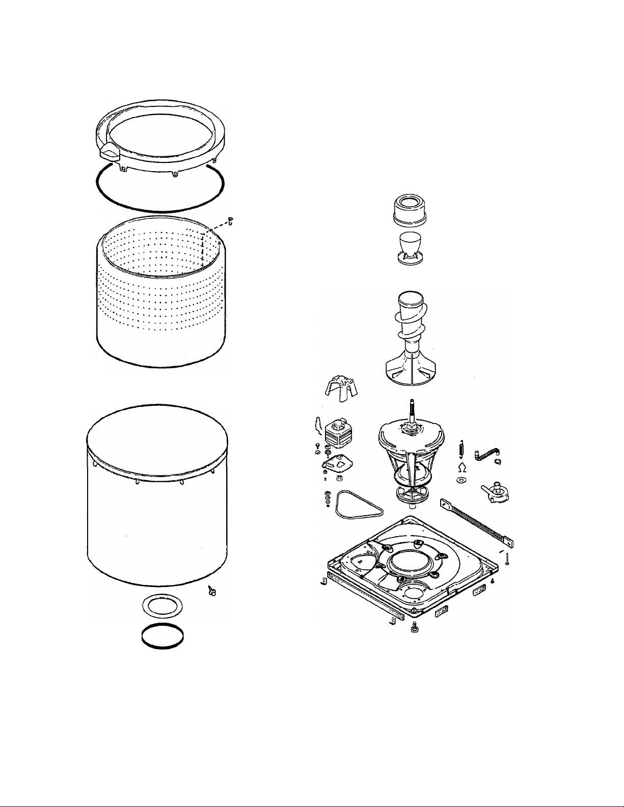
INNER TUB
The inner tub is perforated in a pattern de
signed to allow free flow of the wash and rinse
water for maximum efficiency in removing
sediment, soil deposits, and lint.
The inner tub is constructed entirely of
polypropylene and is secured to the basket
hub assembly with four (4) mounting screws.
A foam gasket is installed between the basket
and the basket hub assembly.
• Position the basket on the basket hub
assembly.
• Align the assembly and tighten all screws
securely.
OUTER TUB ASSEMBLY
The outer tub assembly is molded entirely of
polypropylene.
The outer tub assembly is mounted to the bear
ing and seal housing and to the tub support.
A foam gasket and a rubber seal are installed
between the tub bottom and the bearing and
seal housing.
16009485-01
©1999 Maytag Appliances Sales Company
Section 5. Water Related Components 5-4
Page 45

REMOVAL
NOTE: When reinstalling the tub assembly,
be sure to:
• Protect the air bell nipple.
• Clean all connecting surfaces to ensure
proper sealing.
• Position the gasket and seal on the bear
ing and seal housing.
• Tighten all screws securely.
PUMP ASSEMBLY
Figure 5-7
1. Disconnect power to the unit.
2. Remove the inner tub.
3. Remove the front panel.
4. Disconnect the pump inlet hose from the
outer tub outlet.
5. Remove the screws located on each side
of the tub brace bolts which secure the
tub to the tub support.
6. Remove the mounting screws on the in
side of the tub which mount the tub to the
bearing and seal housing.
7. Disconnect air dome hose.
8. PROTECT THE AIR BELL NIPPLE and lift
the tub from the cabinet.
Pump
Housing
Impeller
Seal
Assembly
NOTE: The air bell nipple is fragile, handle
carefully.
16009485-01
©1999 Maytag Appliances Sales Company
Plate & Pulley
Assembly
Figure 5-8
Section 5. Water Related Components 5-5
Page 46

The pump assembly is located on the right
front corner of the washer base.
The pump pulley is engaged to the drive belt
at all times and will be operating in both mo
tor directions: Clockwise during agitation and
counterclockwise during spin. The pump is
designed so it will only discharge water from
the machine when it is running in the coun
terclockwise, or spin direction.
REMOVAL
1. Disconnect power to the unit.
2. Remove the front panel.
3. Remove the drain hose from the pump
outlet.
4. Disconnect the pump inlet hose.
5. Remove the three (3) screws which
mount the pump assembly to the base.
6. Slide the pump to the rear to disengage
the belt from the pulley.
REPLACEMENT
Place one hand through the pump opening
and lift belt. Set the pump pulley into the open
ing and place the belt on the pulley. While
holding tension on the belt to keep it on the
pulleys, install the mounting screws.
DISASSEMBLY
1. Remove the pump from the washer base.
2. Remove the four (4) screws that secure the
housing to the pump base, and lift off the
housing.
3. Remove the screw that secures the impel
ler.
4. Using two (2) screwdrivers, one on each
side of the impeller, carefully pry the im
peller off the spline shaft.
5. Work the seal mating ring and "O" ring up
and off the shaft.
NOTE: If this is done carefully, the belt will
remain on the motor and transmission drive
pulley, making installation easier.
16009485-01
©1999 Maytag Appliances Sales Company
Section 5. Water Related Components 5-6
Page 47

WATER VALVE INJECTION
SYSTEM
On some models the water valve is installed
at the top rear of the cabinet (Figure 5-1).
The following procedures are used to
remove the water valve.
Figure 5-1
To raise the top asssembly, insert a thin
bladed tool (such as a putty knife) between
the front panel and top assembly
approximately three inches in from each
corner. While lifting up on the top cover
assembly, press the blade against the wire
clips, one side at a time to disengage them.
Lift the top cover up to a stationary position.
(Figure 5-2)
Figure 5-2
With the top assembly up you will have
access to the water valve assembly.
(Figure 5-3)
Figure 5-3
16010280
(16009485-02)
SECTION 5. Water - Related Components
©2000 Maytag Appliances Sales Company
5-7
Page 48

The water valve is held to the cabinet by one
screw. (Figure 5-4)
Figure 5-4
Remove the screw and swing the bracket
and valve assembly to the right to release
the bracket from the cabinet. (Figure 5-5)
The fill hoses can be removed at this point.
Figure 5-7
Remove the wiring from the water valve.
(Figure 5-6)
Remove the screw and using a small flat
bladed screw driver, carefully pry up on the
plastic tab to release the water valve from
the bracket. (Figure 5-9)
Figure 5-5
Figure 5-6
BE SURE THE WATER IS TURNED OFF.
(Figure 5-7)
The water valve is held to the bracket by one
screw and a tab molded into the plastic part
of the bracket. (Figure 5-8)
Figure 5-8
Figure 5-9
16010280
(16009485-02)
SECTION 5. Water - Related Components
©2000 Maytag Appliances Sales Company
5-8
Page 49

Slide the metal part of the bracket out of the
slots in the plastic part of the bracket.
(Figure 5-10)
4. Remove the agitator
5. Remove the mounting screws.
6. Remove the upper insulating ring.
(Figure 5-11)
Figure 5-11
Figure 5-10
Installation of the water valve is the reverse
of the above procedure.
Stainless Steel
Spinner Assembly
The stainless steel spinner is composed of a
crimped stainless steel basket and a
polypropylene spinner top. There is a lower
insulating ring attached to the bottom of the
spinner and an upper insulating ring that fits
over the inner spinner bottom. These
insulating rings provide stability to the lower
spinner area. When replacing a spinner it is
recommended that the insulating rings be
replaced with the spinner assembly.
Lift the spinner up over the center post
and out of the cabinet
8.
Depress the six (6) tabs (Figure 5-12) that
hold the spinner top to the spinner and
remove the spinner top.
Depress the four (4) tabs that hold the
lower insulating ring to the bottom of the
spinner and remove. (Figure 5-12) These
four (4) tabs are not necessary for correct
machine operation. These tabs are used
to assist in the manufacturing process. If
one or more break during removal, the
part is still functional. (See Figures 5-13
thru 5-14)
Removal:
1. Disconnect the power to the unit.
2. Raise the top assembly and lean it back.
3. Remove the tub top.
16010280
(16009485-02)
©2000 Maytag Appliances Sales Company
SECTION 5. Water - Related Components
5-9
Page 50

Spinner top
tab
Figure 5-12
NOTE: When reinstalling the spinner
assembly, be sure to;
• Clean all connecting surfaces to ensure
proper sealing.
• Position the basket on the basket hub
assembly.
• Align the assembly and tighten all screws
securely.
16010280
(16009485-02)
SECTION 5. Water - Related Components
©2000 Maytag Appliances Sales Company
5-10
Page 51

SECTION 6. SUSPENSION SYSTEM
A WARNING
Warning - Always shut off
electrical power to the
washer before beginning any
15
service repair procedures.
The washer utilizes a six-point suspension sys
tem which consists of the suspension housing,
snubber pad, tub braces, suspension springs
and related hardware.
The six-point system features six springs. Three
springs are installed between the base and the
top of the tub brace. The other three are be
tween the base and special spring hooks attached
to the tub support perimeter (Figure 6-1).
16009485-01
Figure 6-1
©1999 Maytag Appliances Sales Company
Section 6. Suspension System
6-1
Page 52

SUSPENSION HOUSING
The suspension housing is fabricated of heavy
gauge steel. It rests on the raised domelike
area in the center of the base and supports
the weight of the transmission, outer tub, and
spin basket (Figure 6-2).
3. Remove the brake assembly as detailed in
Section 7.
/
4. Remove screws securing housing to the
lower bearing assembly.
TUB BRACES
The underside of the suspension housing pro
vides mounting for the snubber pad and also
houses the brake assembly (Figure 2-2).
The bottom of the housing has been formed
into a spherical configuration and, along with
the snubber, rides on the domed area of the
base which allows the housing to move freely
in all directions.
The top of the suspension housing is attached
to the lower bearing assembly with three
mounting screws. These screws thread from
the underside of the suspension housing dome
into the die-cast bearing housing.
Suspension
The tub braces are attached at the top to the
tub support, and to the suspension housing
at the bottom. The tub braces are located
behind iic\e tub support and suspension hous
ing where large, thread forming screws are
driven directly into the braces to secure them.
NOTE: Should a tub brace mounting screw
hole become stripped, a nut can be installed
on the thread forming screw.
The extended end of the suspension spring
fits through an extruded hole in the tub brace
just below the mounting screws.
SUSPENSION SPRINGS
The suspension springs hold the entire wash
unit in firm contact with the base. To reduce
wear and prevent squeaks; grease has been
applied to the friction points of the springs.
Figure 6-2
Service to the suspension housing, other than
replacing it, is limited to replacing one of the
other components that mount to the housing.
The replacement procedures for these com
ponents are detailed in the Transmission Sec
tion of this manual.
REMOVAL
1. Disconnect power to the unit.
2. Remove the transmission assembly as de
tailed in Section 7.
16009485-01
©1999 Maytag Appliances Sales Company
REMOVAL
The suspension springs can be removed and
replaced by using the spring tool, part num
ber 22002922 as follows:
1. Disconnect power to the unit.
2. Remove the front panel and rear access
panel.
3. Pull or block the tub in the direction of the
spring to be removed.
NOTE: Removing the tub top will allow the
tub to travel further and extend the spring less.
Section 6. Suspension System 6-2
Page 53

The new suspension spring tool, part number
22002922, is used to remove and replace the
suspension springs on the Atlantis and the
Performa washers, in addition to earlier mod
els of brand washers.
Adjustment Slots: Use of the upper slot of
the spring too! for the older Performa and
brand washers is recommended. Using the
lower slot on the Atlantis and the 7999
Performas washers will give the best results.
Then proceed with steps as follows:
a) . Hook the mouth of the too! under upper
hook end of spring.
b) . insert blunt end of the too! into the recoil
in the ball at the bottom of the spring.
c) . Squeeze the handies together and unhook
the spring hook from the brace.
Hook mouth of tool
under upper hook end
' of spring
Insert blunt end of tool
into recess in the base
at the bottom of the
spring
^ SL451TIF
Figure 6-4
4. Spring replacement is a reversal of the
above.
NOTE: Be sure to grease the friction points of
the replacement springs before installing.
SPRING TOOL 22002922
Squeeze the handles
together and unhook
the spring hook from
the brace
SL461T1F
Figure 6-5
IMPORTANT
No attempt should be made to
remove or install the springs with
pliers, vise-grips or anything other
than the spring tool, as damage to
the springs could occur. When
attaching the springs to the base
for installation, make sure the
spring end is protruding up,
through the small triangular cut
out next to the deboss.
16009485-01
©1999 Maytag Appliances Sales Company
Section 6. Suspension System
6-3
Page 54

16009485-01
©1999 Maytag Appliances Sales Company
Section 6. Suspension System 6*4
Page 55

SECTION 7. TRANSMISSION AND RELATED
COMPONENTS
A WARNING
This section will detail the servicing proce
dures on the transmission assembly which has
splines formed on the agitator drive shaft.
Warning - Always shut
off electrical power to
the washer before begin
ning any service repair
procedures.
An "O" ring is installed on the shaft just above
the seal nut assembly to provide an air seal
when the agitator is installed.
16009485-01
©1999 Maytag Appliances Sales Company
Section 7. Transmission And Related Components 7-1
Page 56

SEAL NUT ASSEMBLY
The seal nut assembly consists of a lip seal
against the agitator shaft.
The seal nut assembly is threaded to the bas
ket hub assembly. A small rubber gasket is
installed in a groove on the bottom flange of
the seal nut assembly. A foam gasket is placed
between the bottom of the spin basket and the
basket hub assembly.
The seal nut assembly can be removed after
removing the spin basket, and the agitator
shaft "O" ring.
REMOVAL
1. Lift the top cover.
2. Remove the tub cover.
3. Remove agitator.
4. Remove the Spin Basket.
5. Remove agitator shaft "O" ring.
6. Unthread the spin nut assembly from the
basket hub assembly, by turning counter
clockwise.
UPPER BEARING AND SEAL HOUSING
The glass filled copolymer bearing and seal
housing assembly slips over a machined area
on the upper drive tube. The basket hub as
sembly threads down over the drive tube and
secures the bearing and seal housing together
(Figure 7-2).
The spin bearing and the tub seal are installed
in a cavity in the center of the housing. The
sheet metal tub support is attached to the
under side of the housing with three (3)
mounting screws. The spin bearing has been
pressed into the underside of the housing cav
ity and is secured by the tub support. The
center of the tub assembly mounts to the up
per flange of the housing with a tub gasket
and a tub seal installed between. The bottom
of the tub sits on, and is attached to, the tub
support.
REMOVAL
1. Disconnect power to the unit.
2. Raise top cover and remove front panel.
3. Remove the agitator, spin basket, agitator
"O" ring, spin nut and outer tub assembly.
4. Remove the basket hub assembly by turn
ing it in a counterclockwise direction, us
ing tool number 35-2968.
5. Remove the suspension springs with the
spring tool.
6. Unbolt the tub braces from the tub
support.
7. Lift up on the bearing and seal housing
with tub support attached.
8. To remove tub support, remove mounting
screws from under the tub support.
16009485-01
Section 7. Transmission And Related Components 7-2
©1999 Maytag Appliances Sales Company
Page 57

TUB SEAL
TUB SEAL REPLACEMENT
The tub seal consists of the seal face and seal
body.
NOTE: All parts of the sea! must be replaced
if either of the sealing surfaces is damaged.
The seal face fits into a recess in the under
side of the basket hub assembly. Also, the seal
body installs in the cavity on the top side of
the bearing and seal housing. The spin bear
ing is located in a cavity on the underside of
the bearing and seal housing.
Each of the two sealing parts, the seal face
and the seal body, have sealing faces which
are brought into contact with one another
when the basket hub assembly is threaded
down on the drive tube. The springs in the
seal body exert pressure to keep the sealing
faces in contact.
The tub seal fits into a recess on top of the
upper bearing and seal assembly.
Should the tub seal begin to leak or develop
excess seal drag, it must be replaced. The
service replacement seal includes all the parts
necessary to replace the entire seal. Be sure
to replace all parts of the seal even if only one
part is found to be damaged.
NOTE: If the tub sea! is being replaced be
cause it has begun to leak, the spin bearing is
probably damaged as well and should be re
placed. To replace the spin bearing, the bear
ing and sea! housing must be removed as pre
viously described. This also allows access to
the tub seal for removal and replacement (re
fer to steps 2 and 3 below when installing).
Removal and replacement of the tub seal can
ONLY be accomplished as follows:
1. Follow steps 1 through 4 of the bearing
and seal housing removal as previously
described. The parts of the seal can now
be removed from their mounting recesses.
The carbon ring of the tub seal mates with the
teflon ring underneath the spin basket hub.
Seal Face
Seal Body
Figure 7-3
2. Before installing the new seal, make sure
both seal mating surfaces are free of for
eign matter, then clean both surfaces with
an alcohol saturated cloth.
NOTE: Make sure no grease comes in con
tact with the mating surfaces of the seal.
NOTE: Do not use any agent other than al
cohol to dean the mating surface. Do not use
any lubricant other than water.
16009485-01
Section 7. Transmission And Related Components 7-3
©1999 Maytag Appliances Sales Company
Page 58

UPPER SPIN BEARING
The spin bearing is installed in a cavity on
the underside of the bearing and seal
housing and is further secured in place by
the inner diameter of the tub support.
SPIN BEARING REPLACEMENT
1. Disconnect power to the unit.
2. Remove the upper bearing and seal hous
ing and the tub support as previously de
scribed.
3. Remove the seal body from the housing
cavity.
4. Press the spin bearing out of the cavity
from the opposite side of the housing.
5. When installing the replacement bearing
into the housing cavity, be sure to press
against the outer race of the bearing to
avoid damage to the bearing shield and
causing premature failure.
DRIVE PULLEY AND CAMS
The drive pulley and cam is located below
the brake assembly on the drive shaft.
Models are equipped with a plastic drive
pulley which has the upper cam molded
onto the bottom of the hub. The purpose of
the pulley and cam arrangement is to drive
the clutch assembly during the agitate and
spin cycle, and to disengage the brake as
sembly during the spin cycle.
The drive pulley slips over the drive shaft and
rests against a series of washers, a thrust
bearing, and a large washer type spacer. The
spacer locates against the bottom of the
brake rotor and lining assembly.
(See the
illustration on page 7-6.)
The lower cam slips over the end of the drive
shaft where splines formed in the cam en
gage with mating splines on the drive shaft
end. This imparts a direct drive from the cam
to the drive shaft. A shoulder molded on the
bottom of the pulley hub engages "dogs"
formed on the sides of the lower cam, and
will drive it and the drive shaft in either di
rection.
A washer and retaining ring secure the pul
ley and cam on the drive shaft. A plastic dust
cap snaps to the underside of the pulley to
keep the cam surfaces clean.
OPERATION
When the drive pulley rotates CLOCKWISE,
the upper and lower cams are designed to
nest together which allows the drive pulley
to remain in position on the drive shaft. The
break remains engaged and the drive pulley
will turn the lower cam and drive the shaft
to cause the transmission to agitate.
When the drive pulley rotates COUNTER
CLOCKWISE, the upper cam and pulley ride
up the lower cam approximately 3/16 of an
inch before the driving shoulders on the pul
ley hub engage the "dogs" on the lower cam.
This causes the top of the pulley hub to push
against the spacer which compresses the
brake spring and lifts the brake rotor and lin
ing assembly off the brake stator. The brake
is disengaged and the pulley will turn the
lower cam and drive shaft to cause the trans
mission to spin.
16009485-01
Section 7. Transmission And Related Components 7-4
©1999 Maytag Appliances Sales Company
Page 59

Transmission
' Housing
Assembly
Lower Bearing
And Housing —
Assembly
Oil Seal'
Suspension
Housing
Brake Spring
Retainer
Retaining
Ring
Drive Tube
Splines
Thrust Bearing
Washer (Curved)
Outer Edge
Turned Up
j Drive Pulley
I Assembly
Lower Cam ■
Spacer
I
o
Washer (thin)
~ Upper Race
O) t Washer (thick)
Lower Race
Washer (thin)
Thrust
Brake Rotor
And Lining
Assembly
Brake
Stator
16009485-01
Retaining
Figure 7-4
©1999 Maytag Appliances Sales Company
-Thrust
Washer
Ring
■ Dust Cap
Section 7. Transmission And Related Components 7-5
Page 60

REMOVAL
1. Disconnect power to the unit.
2. Tip the unit over and remove the drive belt.
3. Remove the dust cap from the under side
of pulley.
4. Remove retaining ring and washer from
end of drive shaft.
5. Firmly pull lower cam off the drive shaft
splines, then slide the other parts off the
shaft. This will also allow access to the
brake assembly for removal.
REPLACEMENT
After reassembling the components on the
drive shaft, it will probably be necessary to pull
down on the shaft to take the end play out of it
before the thrust washer and retaining ring can
be reinstalled.
Counting the reference marks on the lower
cam from right to left, the pulley hub shoul
der should be positioned between refer
ence marks 9 and 4 with 6 being the
median (Figure 7-5).
NOTE: Each time the cams are reassembled
on the drive shaft, the point in the cam rise
where the brake disengages the stator should
be checked and adjusted as necessary.
Reference marks have been molded around
the bottom outer edge of the lower cam as an
aid in checking the point of brake disengage
ment (Figure 7-5). Each mark, from right to
left, represents approximately .010 of an inch
cam rise.
To Check Brake Disengagement:
1. Manually rotate the drive pulley in a slow
counterclockwise direction until the brake
starts to release and the transmission be
gins to turn (Figure 7-5).
If the position of the pulley hub shoulder /s
not within these parameters and the brake has
started disengaging, adjustment is required.
To Adjust Brake Disengagement:
1. If the position of the pulley hub shoulder
is less than 4 reference marks, remove the
standard (.062 thickness) thrust washer
and replace it with a thinner (.032 thick
ness) thrust washer (part number
35-2132). Recheck disengagement.
2. If the position of the pulley hub shoulder
is more than 9 reference marks, add a
35-2132 thrust washer (.032) to the
standard thrust washer and recheck
disengagement.
16009485-01
Section 7. Transmission And Related Components 7-6
©1999 Maytag Appliances Sales Company
Page 61

BRAKE AND SNUBBER ASSEMBLY
DISASSEMBLY
NOTE: This is a dry operating brake
assembly.
The brake assembly is located inside the
domed area of the suspension housing and
consists of the following components: brake
spring retainer, brake spring, rotor and lining
assembly and the brake stator.
The brake assembly, as well as the snubber, is
held In position by the brake stator which is
secured to the underside of the suspension
housing by six mounting screws.
Spring pressure forces the rotor and lining
assembly down on the brake stator and pre
vents the transmission from turning during
agitation.
As stated previously, the drive pulley and
cams provide a cam action which raises the
drive pulley during the counterclockwise
(spin) direction of the motor. When the drive
pulley hub travels upward, it compresses the
brake spring and moves the rotor and lining
assembly up the drive tube disengaging it from
the stator. The transmission is now free to
spin.
1. Disconnect power to the unit.
2. Remove the drive pulley and cam compo
nents as previously described.
3. Using brake removal tool number LA-2004,
proceed as follows:
• Pull out and remove "U" retainer from
tool.
• Slip the splined end of the drive shaft
into hole located in the tool inner
plunger.
• Looking at the side of the tool, align
slots on tool barrel and holes in tool
plunger between splines and cham
fered shoulder of shaft.
• Slip "U" retainer through tool slots and
holes capturing the drive shaft behind
the chamfered shoulder.
• NO TE: Be sure the ”LT retainer is com
pletely through both sides of tool.
• Tighten tool nut to compress brake
spring until transmission turns freely.
Splines in the brake rotor hub mesh with
splines on the drive tube end to provide posi
tive vertical movement for the rotor and lin
ing assembly. The splines are greased for ease
of movement.
^ CAUTION
The brake assembly has a compressive
spring force of approximately 200pounds.
See the following instructions for
disassembly.
16009485-01
©1999 Maytag Appliances Sales Company
• Remove six (6) screws which secure
the brake stator and snubber to the
underside of the suspension housing.
• Loosen tool nut until the brake soring
reaches its free length.
• Remove "U" retainer from tool and re
move tool from drive shaft.
• Remove brake components.
Section 7. Transmission And Related Components 7-7
Page 62

BRAKE REPLACEMENT
SNUBBER REPLACEMENT
1. Apply silicone grease (part number
203959) to the splines of the drive tube and
rotor, if needed.
NOTE: This is a dry operating brake assem
bly. Make sure no oH or grease comes in con
tact with the mating surfaces of the brake lin
ing and/or brake stator. Clean both surfaces
with an alcohol saturated doth before
assembly.
2. Compress the brake spring until the stator
and snubber fit firmly against the suspen
sion housing before affixing the mounting
screws.
3. Follow the drive pulley and cam reassem
bly as detailed previously.
1. Remove belt.
2. Lift top cover and remove front panel.
3. Remove tub to pump hose and air bell
hose.
4. Remove six suspension springs.
5. Lift complete tub and drive assembly out
of cabinet, then carefully place onto floor.
Be careful not to damage the air bell nipple
on the outer tub.
6. Remove pulley and brake assembly.
7. Remove snubber.
8. To reassemble; reverse above steps.
16009485-01
Section 7. Transmission And Related Components 7-8
©1999 Maytag Appliances Sales Company
Page 63

TRANSMISSION ASSEMBLY COMPLETE (Non-Repairable)
Rack Gear
Carrier
Transmission
Cover
Cluster
Gear
Agitator
"shaft
r
Bearing
Housing
Transmission
Housing
Input Pinion
Output
j~ Pinion
Crank
Gear
-Wings
16009485-01
Lower
Seal
SL295TIF
Figure 7-6
Section 7. Transmission And Related Components 7-9
©1999 Maytag Appliances Sales Company
Page 64

The die-cast aluminum transmission housing
has four studs pressed into its upper region.
The studs provide mounting for the two crank
and two cluster gears. The top cover is
threaded into the lower housing. A sealant is
used on the threads as a gasket material. A
steel drive tube with a splined end is pressed
into the bottom of the transmission housing.
A sleeve bearing is installed in the lower I. D.
of the drive tube. Another bearing is pressed
into the lower housing above the drive tube.
These bearings provide a path for the drive
shaft to ride in. An oil seal is installed in the
bottom of the drive tube. The oil seal can be
replaced as a separate part.
Use tool part number 2000021. Remove
the old seal from the lower housing
(Figure7-7a thru 7-7c).
,7''
Oil Seal Replacement
The oil seal is located in the spline end of the
drive tube. The seal can be replaced without
removing or disassembling the transmission,
as outlined below:
1. Disconnect power to the unit.
2. Remove the brake assembly to access the
oil seal (Figure 7-4).
\
Figure 7-7
Seal Removal Tool, Part Number 2000021
16009485-01
©1999 Maytag Appliances Sales Company
Section 7. Transmission And Related Components 7-10
Page 65

4. Place the new seal over the seal protector.
5. Place the seal protector tool, by sliding the
tool over the drive shaft and up to the seal
cavity (Figure 7-7d).
7. Pull the rings with the insertion tool to re
move, thus leaving the new oil seal on the
drive shaft (Figure 7-7f).
6. Slide the transmission seal driver (tool
number 2000021) over the drive shaft un
til it makes contact with the drive washer.
Use a hammer to "tap" the seal into the end
of the drive tube (Figure 7-7e).
LOWER BEARING ASSEMBLY
The lower bearing assembly provides lateral
support for the drive tube and shaft against
the tension of the drive belt. The top of the
suspension housing is attached to the under
side of the lower bearing assembly.
The lower bearing assembly consists of a ball
type bearing which has been installed in an
aluminum die-cast housing. The transmission
assembly must be removed from the washer
cabinet before the lower bearing assembly
can be replaced.
16009485-01
©1999 Maytag Appliances Sales Company
Section 7. Transmission And Related Components 7-11
Page 66

REPLACEMENT
3. Remove the cams, drive pulley, and
brake assembly.
IMPORTANT
Because the lower bearing assembly has
been pressed onto the drive tube under
approximately 1,000 pounds of pressure,
a puller must be used to remove it. How
ever, the puller forcing screw must not
be used on the end of the drive shaft or
the dutch assembly could be damaged.
Instead, a simple pipe and cap assembly
can be made to slip over the drive shaft,
with end clearance, and rest against the
end of the drive tube.
The puller forcing screw is used on the end of
the pipe cap which directs the forward thrust
of the puller to the bottom of the drive tube.
REMOVAL
4. Remove the three (3) screws which
secure the suspension housing to
the lower bearing assembly.
5. Slip the pipe and cap assembly over
the drive shaft and up against the
drive tube.
6. Using a puller with at least a 3 1/2
inch spread and sufficient reach to
encompass the pipe and cap assem
bly, remove the lower bearing as
sembly (Figure 7-8).
NOTE: When installing the new lower bear
ing assembly, be sure to drive against the in
ner race only to avoid damaging the bearing
shield which could cause premature Jailure.
1. Disconnect power to the unit.
2. Remove the transmission from the
washer cabinet.
Transmission
Figure 7-8
16009485-01
Section 7. Transmission And Related Components 7-12
©1999 Maytag Appliances Sales Company
Page 67

DIAGNOSING TRANSMISSION PROBLEMS
V-
Listed below are most of the service com
plaints which would normally be caused by a
malfunctioning component of the transmis
sion assembly.
Oil Leaks
Oil leaks can be caused by faulty seals, gas
kets, or a loose fitting stud.
Slow Spin Speed
Slow spin speed can be caused by a binding
tub seal and/or bearing, brake rotor assembly
not disengaging properly, a slipping clutch
spring, or an off balance load. The test that
follows can be used to isolate the problem.
The torque available to drive the spin basket
is determined by the amount of drag or resis
tance presented by the tub seal and spin bear
ing, deducted from the input torque imparted
to the transmission housing assembly by the
clutch assembly.
The Following Torque Tests Will Allow a Prob
lem in the Spin Drive Train to be Pinpointed:
NOTE: Before starting these tests, the
washer should be operated in the agitation
cycle with hot water for about two (2) min
utes, and then for two (2) minutes in a spin
cycle. This warms up the transmission oil and
the spin drive train components.
Available Torque
TORQUE TESTING
A quick test of the efficiency of the spin op
eration components can be made by placing
a 3 1/2 pound weight, such as a bag of sand,
in the washer basket and starting the machine
in the spin cycle. If the basket appears to reach
full spin with the weight, the machine com
ponents are performing as intended. If the
basket does not attain full spin speed, the
torque test procedures as outlined in the fol
lowing paragraphs should be performed to
determine the problem.
16009485-01
©1999 Maytag Appliances Sales Company
Place a 1/2 inch socket and torque wrench on
the agitator retaining bolt.
Depress the safety spin switch to allow the
washer to operate in the spin cycle, then while
reading the torque allow the wrench to turn
slowly (about 6 R.RM.) through a complete 360
degree cycle. The reading should be between
18 and 25 inch pounds throughout the com
plete 360 degree rotation of the wrench.
Section 7. Transmission And Related Components 7-13
Page 68

If the torque readings are within these limits,
the washer is performing properly and any
slow spin complaints can be assumed to have
been the result of off- balance loads.
If the torque reading exceeds 25 inch pounds,
the input torque outlined later should be
checked to determine the cause. Probable
causes may be the drive shaft is binding in
the transmission housing (drive tube) sleeve
bearings, or that the clutch spring is binding
on the drive shaft hub.
If the available torque reading is less than 20
pounds, follow the procedure for testing the
drag torque.
Drag Torque
Position the washer so the drive pulley can be
accessed, and remove the drive belt. While
holding the transmission to keep it from turn
ing, manually rotate the drive pulley counter
clockwise until the brake stays disengaged.
Make certain the drive pulley hub shoulder
has rotated fully against the cams in the spin
driving position to ensure the complete dis
engagement of the brake. Release the trans
mission so it is free to turn.
Place a 1/2 inch socket and torque wrench on
the agitator retaining bolt.
If the available torque reading is below 18 inch
pounds and the drag torque reading is not
over 4 inch pounds, follow the procedure for
checking the clutch assembly as to its input
torque.
Input Torque
NOTE: it will be observed that the readings
used to check the input torque are slightly
lower than the readings used to check the
available torque. The reason for this is when
the brake is disengaged, as in checking the
available torque, the compressed brake
spring exerts a downward force on the bot
tom of the dutch hub and thrust washers.
This keeps the dutch spring from slipping
quite as readily as in checking the input
torque where the brake is engaged and the
downward force on the dutch hub is mini
mized.
To check the input torque, remove the drive
pulley and position the washer so the scale
on the torque wrench can be read when it is
placed on the input (drive) shaft. Attach the
torque wrench adapter firmly to the shaft,
place the wrench in the adapter and slowly
rotate the wrench in a counterclockwise di
rection. A properly operating clutch assem
bly will have a torque reading between 18 and
22 inch pounds.
Slowly rotate the wrench 360 degrees at ap
proximately 6 R.RM. and read the torque. If
the torque reading is over 4 inch pounds, re
move the brake stator (as detailed earlier in
this section) and recheck the drag torque.
If the torque reading is now under 4 inch
pounds, the brake is binding and should be
repaired.
If the reading is still over 4 inch pounds, the
tub seal and/or spin bearing is binding and
should be replaced.
16009485-01
©1999 Maytag Appliances Sales Company
If the input torque is less than 18 inch pounds,
the clutch assembly is damaged and the com
plete transmission must be replaced.
If the input torque exceeds 22 inch pounds,
the drive shaft is binding in the sleeve bear
ings, and the complete transmission must be
replaced.
Section 7. Transmission And Related Components 7-14
Page 69

TRANSMISSION REMOVAL
The transmission assembly can be removed
from the washer cabinet after removing the
drive belt, spin basket, outer tub and the sus
pension springs.
NOTE: // the "O" ring is to be reused, be ex
tremely careful not to damage it during the
removal.
To assist in correctly positioning the tub, a
small indentation has been formed on the tub
support just above one of the tub brace
mounting areas. This is the left front tub brace.
When the tub is in proper position and ready
to be mounted to the tub support, the large
tub cover lock (on the side of the tub) should
be located directly above the indentation and
tub brace (See Page 7-16).
Remove the "O" ring and agitator once the
drive train is back in place.
The transmission assembly, when removed
as described, will have the related components
assembled to it. These related components
should be examined carefully before reinstall
ing.
IMPORTANT
When installing the transmission, it is
necessary that the tub be located on the
tub support a certain way if all the
mounting holes are to be properly
aligned. This should be done before at
tempting to mount the tub to the bear
ing and sea! housing.
16009485-01
Section 7. Transmission And Related Components 7-15
©1999 Maytag Appliances Sales Company
Page 70

Tub
16009485-01
TUB TO TUB SUPPORT ALIGNMENT
Figure 7-10
Section 7. Transmission And Related Components 7-16
©1999 Maytag Appliances Sales Company
Page 71

SECTION 8. ELECTRICAL COMPONENTS & TESTING
ELECTRICAL TEST EQUIPMENT
The equipment required to service Maytag
products depends largely upon the conditions
you encounter. Locating a malfunction will
Description
Analog Test Meter
Digital Test Meter
Clamp-on Ammeter
AC Voltage Sensor
Analog Test Meter
can be used to check for
open or closed circuits,
measure resistance, AC
and DC volts, and
temperature.
often require the use of electrical testing
equipment such as:
Part Number
20000005
20001001
20000002
20000081
Clamp-On Ammeter
can be used to detect
shorts. Overloads on
the circuit
breaker or fuse
can be traced
to either the
washer or circuit
breaker by check
ing the washer
current draw.
W
Digital Test Meter
can be used to check for
open or closed circuits,
measure resistance,
AC and DC volts, and
temperature.
16009485-01
AC Voltage Sensor
can be used to alert you if
AC voltage is present so proper
safety precautions can be observed.
The tip of the sensor will glow bright
red if voltage is between 110-600
volts AC.
Section 8. Electrical Components & Testing 8-1
©1999 Maytag Appliances Sales Company
Page 72

ELECTRICAL TESTS
TIMER
Warning - Always shut off
electrical power to the
washer before beginning
any service repair
procedures.
Grounded Components
When performing service diagnostics, re
placements and repairs, always check to de
termine whether all ground wires linking
panel and components are reattached if
removed.
Voltage Checks
Generally, these checks will consist of taking
readings at the wall receptacle to determine
the availability of voltage to the product. Volt
age checks on individual components of a
product are not recommended due to the
possibility of electrical shock. Component part
testing is best accomplished through conti
nuity checks with an Appliance Test Meter
{See Electrical Test Equipment).
NOTE: Use of the meter on voltage higher
than the indicated range may cause perma
nent damage to the meter. To prevent dam
age, first select the highest range and then
lower the range for readings which fall within
the lower scale.
Set UP meter for use as follows:
1.
Turn selector knob to desired meter func
tion and appropriate range.
Plug black lead into socket marked
black {-).
Plug red lead into socket marked red (+).
3.
Place test leads into receptacle to deter
4.
mine voltage available.
The timer is mounted inside the control con
sole assembly. The timer shaft protrudes
through the control panel and provides for the
selection of the various machine cycles
available.
The timer is an incremental advance, rotary
type driven by a synchronous motor. The
timer controls and sequences the numerous
steps and functions involved in each machine
cycle. It accomplishes this by providing power
to the various electrical components through
the opening and/or closing action of timer
contacts.
A typical timer and plug connector are illus
trated in Figure 8-1. The timer has all the con
necting points brought out to miniature spade
terminals. These terminals are centralized and
aligned on one side of the timer to form a
terminal board.
The connecting wires from the wiring harness
are terminated in a compatible connector
which plugs into the timer terminal board.
Since space is notably limited on the timer
terminal board, terminal identification is pro
vided by a sticker attached to the side of the
timer. When referring to the sticker for termi
nal identification, the external timer motor
wires can be used for orientation.
Another source for terminal identification is
the schematic diagram which is supplied with
each washer. The schematic diagram not only
identifies the terminals, but also the plug con
nector terminals and their respective wire
colors.
16009485-01
©1999 Maytag Appliances Sales Company
Section 8. Electrical Components 8 Testing
8-2
Page 73

TERMINAL BOARD
Figure 8-1
REMOVAL
Timer removal procedures are detailed in Sec
tion 4 under Control Pane! Assembly Re
moval.
Timer Testing
The timer can be tested by using an ohmmeter and the Timer Sequence Chart as detailed
in the following.
TIMER SEQUENCE CHART
The following chart depicts a typical Timer
Sequence Chart which can be found on the
schematic diagram. It denotes the internal
timer contacts which are opened and/or
closed by the timer cam switches at any in
terval during a machine cycle.
Listed down the side of the chart at the left,
each contact in the timer is identified as be
ing controlled by a particular cam. The func
tion of each contact and its terminal designa
tion is also indicated.
Across the bottom of the chart are the vari
ous machine cycles available for selection, and
the timer increments at which the cycle be
gins and ends. The increment, or degree di-
vision, indicates the travel of the timer through
a cycle.
The heavy black lines to the right of the termi
nal column indicate a closed contact. If the
contact is open, there is a break in the heavy
black line.
EXAMPLE
Cam 0 shows the switch arm dosed, mak
ing contact between Line 1 and wire 44
from increments 4 through 18. This cir
cuit is the cam controlled ON/OFF switch
in the timer and at increment 19 it opens,
shutting the machine off (Figure 8-2).
Using the Time Sequence Chart
The sequence chart used in conjunction
with an ohmmeter can be quite effective when
attempting to verify or diagnose problems in
the timer, wiring, or other electrical parts.
In order to establish exactly which electrical
components should be operating during any
given time throughout the various machine
cycles, it is only necessary to determine what
particular cycle and phase of the cycle you
are interested in.
Once the cycle and phase have been ascer
tained, locate these along with the increment
at the bottom of the Timer Sequence Chart.
When the cycle, phase and increment are lo
cated, follow the increment from the bottom
to the top of the chart noting which timer con
tacts are involved in the area of concern.
Once the timer contacts have been deter
mined, the electrical circuits involved can be
traced on the connection diagram by incre
ment or by phase, if necessary.
16009485-01
©1999 Maytag Appliances Sales Company
Section 8. Electrical Components & Testing 8-3
Page 74

A point to point continuity check can be made
to isolate the trouble either in the timer, wiring
harness, or other electrical components after
the circuit has been traced.
Figure 8-2
AUTOMATIC TEMPERATURE CONTROL BOARD
The temperature control board receives in
formation from the water temperature switch
as to the user's water selections. The ther
mistor located in the water valve, provides
inputs to the board, as to what temperature
the incoming water is. This information com
bined with the selections on the temperature
control switch determines the output signals
to the water valve.
Temperature control boards are found on
models MAV6000, MAV6057, MAV7000,
MAV7057, MAVBOOO, MAV8057 and MAV8500
only. Two different types of boards are used
on the washers. An analog temperature board
is used on models MAV6000, MAV6057,
MAV7000 and MAV7057. A microprocessor
temperature control board is used on models
MAV8000, MAV8057 and MAV8500.
SL281TIF
The target cold temperature is a 75° F., plus or
minus 5° F. Targeted Warm temperature is 95°
F, plus or minus 5° F.
Keep in mind that the control system is in
tended to warm wash fills when necessary to
the target temperature. It will not cool a fill
when the inlet temperatures exceeds the mini
mum target temperatures.
Analog Temperature Control Board
The analog board, depending on the water
temperature selected, will monitor the water
temperature and will turn the valves ON and
OFF to maintain proper water temperature.
When the water temperature is set on Warm,
both valves are on. The longer the valve is ON,
the cold water temperature in the water lines
eventually drops lower and lower.
16009485-01
©1999 Maytag Appliances Sales Company
Section 8. Electrical Components & Testing
8-4
Page 75

When this occurs, the АТС will shut the cold wa
ter valve off for a brief period of time and turn it
back on to maintain a proper temperature flow.
You will note in the following table, the only
combinations where the temperature control
board is active (BOLD) are Warm and Cold
Rinse fills are not temperature controlled unless
Warm Rinse is selected. During activation, the
indicator light is only ON when the board is con
trolling water temperatures.
The following chart (Figure 8-3) depicts the
with the temperature control selector in the
ON position. When Cold is selected and the
temperature sensed by the thermistor is too
low at the valve, the Hot valve will be activated.
philosophy on how the Automatic Tempera
ture Control Board operates. Note, the Ther
mistor Temp represents the temperature
sensed by the thermistor in the water valve.
When Warm is selected and the temperature
sensed by the thermistor is too cool, the Cold
valve will be shut off.
The outputs are indicative of the board send
ing voltage to the water valve solenoids.
Analog Automatic Temperature Control (АТС) Truth table:
Water Temp
Selections
АТС
Selector
Thermistor
Temp
Hot Valve
Output
Hot Off Low On
Warm
Cold Off Low
Hot Off High
Off
Low On On
Off
On
Warm Off High On On
Cold
Hot On
Warm On
Cold
Hot On
Warm On
Cold On
Analog Temperature Board Tests
In order to test the board for proper function,
we need to monitor incoming and outgoing
signals to and from the temperature control
board. The chart shown on the next page pro
vides a listing of the eleven terminal pin con
nections (Figure 8-4) of the board, their source
or function, and identifies outputs/inputs
(Figure 8-5).
Off
On
High Off On
Low On
Low On Off
Low On On
High On Off
High On
High
Figure 8-3
Off
GY
PK PU GY
47
4
3 47
11 10 987654321
Cold Valve
Output
Off
On
Off
Off
On
On
BR
51
WIRE INSERTION SIDE
Figure 8-4
BK
12
YL
35 13
OR
Indicator
Light
BU
PLU G
11 7N
Off
Off
Off
Off
Off
Off
Off
On
On
Off
On
On
WH
SL282TIF
16009485-01
©1999 Maytag Appliances Sales Company
Section 8. Electrical Components & Testing 8-5
Page 76

ANALOG TEMPERATURE CONTROL BOARD DIAGNOSTICS FOR
MAV6000, MAV6057, MAV7000 and MAV7057
OUTPUT/
PIN SOURCE
1
Neutral
Not Used
2
3 Cold Valve Output
4 Hot Valve
5 Indicator Light
6
Timer (12 T Contact)
7
TC Disable Input
8 Thermistor
9 Temp Selector
Switch Cold Wash
INPUT
Input
Output OR
Output YL
Input BK
Input GY
Input PU 6 * **
WIRE
COLOR
WH
BU
BR
MEASURE
TO PIN #
Line 120VAC
1
1
1
1
6 *
11 10K-100K
VOLTS
OHMS
120VAC
120VAC
120VAC
120VAC
OVDC
3-24VDC
OHMS
OVDC
CONDITIONS
TC Option Selected Warm
or Cold Wash Selected
Wash Cycle on Timer
TC Option Deselected
TC Option Selected
Room Temperature
Warm or Cold Wash
Selected
10 Temp Selector Switch
Hot Wash
11 Thermistor
* Reference DC Voltages to Line 1.
* * Temperature only occurs during Cold or Warm wash fills.
Input
Input
PK
GY
Figure 8-5
6 * **
8
MICROPROCESSOR TEMPERATURE CONTROL BOARD
The microprocessor temperature control
board has the temperature control features of
the analog board, with the additional func
tions of finger tip faucet, rinse fills, spray rinses
ture fill. All fills after this will not be tempera
ture controlled through the АТС. Meaning the
Temperature fill will be what is selected on
the temperature selection switch.
and end of cycle signal. On Model MAV8500
only, the АТС temperature control can blend
the proper selected water temperatures dur
ing the initial water fill. To activate this fea
ture, the Temperature Control option must be
activated. The first fill at the initial start-up of
the washer will have a blended water tempera
Finger Tip Faucet
The faucet is controlled through a rocker
switch on the control console. The fill circuit
is fed through the temperature control board
then to the water valve. As long as the pres
sure switch is not satisfied, the finger tip
OVDC
10K-100K
OHMS
Hot or Warm Wash
Selected
Room Temperature
16009485-01
©1999 Maytag Appliances Sales Company
Section 8. Electrical Components & Testing
8-6
Page 77

faucet option will function. When the pressure
switch is satisfied, the faucet will no longer
function.
End of Cycle Signal
The signal will sound at the end of the final rinse.
Note, the signal will not sound for 150 seconds
into the cam closure. Software built into the
board enables the board to perform this func
tion. The washer will continue to spin for 15-20
seconds at the end of the signal. On Model
MAV8500 only, the reminder chime will sound
repetitively every four minutes. This will con
tinue until the timer knob is depressed, the re
minder chime option switch is deselected or the
water fill level is increased.
Signal intensity is controlled by the user us
ing a rocker switch on the control console.
The rocker switch can be checked at the
temperature control board terminal con
nector (Figure 8-6) using the following
chart, along with other machine functions
(Figure 8-7).
TEMPERATURE CONTROL CONNECTOR
GY
BU
11 13
19 18 17 16 15 14 13 12 11 10 9 8 7 6 5 4 3 2 1
GY PK BUPUBR PU RD OR YL
OR
47 47 4
25
51 3 27 26 29
MRBiNUIRICNtW
Figure 8-6
BU OR
RD YL
PU
LI 35
37 39
PUX
WH
7N
16009485-01
©1999 Maytag Appliances Sales Company
Section 8. Electrical Components & Testing 8-7
Page 78

MICROPROCESSOR TEMPERATURE CONTROL BOARD DIAGNOSTICS
MAV8000 & MAV8057
OUTPUT/
PIN
1 Neutral
2 Not Used
3 WaterValve-Hot Output
4
5 Indicator Light Output YL
6 Line 1 Input
7
8
9 Chime Soft Input
10 Chime Loud Input RD
11
12 Temp Control Enable
SOURCE
Cold Valve Output
Fingertip Faucet Input
Timer Input (Chime)
Temp Selector
Switch - Cold Wash Input PU
INPUT
Input WH
Input YL
Input
WIRE
COLOR
MEASURE
TO PIN #
OR
BU 1
RD
RD
PU
OR
BR
VOLTS
OHMS
Line
1 120VAC
1 120VAC
1
6
6
6 12-24VDC Soft Chime Selected
6 12-24VDC
6 OVDC
6
120VAC
120VAC
120VAC
OVDC
12-24-24VDC
12-24VDC
5VDC
12-24VDC
OVDC
12-24VDC
CONDITIONS
АТС Option Selected
Warm or Cold Wash
FF Button Not Pushed
FF Button Pushed
Contact 9T or9B Closed
Contact 9T or 9B Opened
Loud Chime Selected
Warm or Cold Wash
Selected
Warm or Cold Wash
Deselected
Option Deselected
Option Selected
Fingertip Faucet
13
14 Chime Switch
Temp Selector
Switch - Hot Wash
15
16 Thermistor
17
Thermistor
Temp Selector
18
Switch - Warm Risnse
19 Cold Rinse Input BU
16009485-01
Output PU 6
Output
Input
Input GY
Input
Input OR 6 OVDC Warm Rinse Selected
©1999 Maytag Appliances Sales Company
BU
PK
GY
Figure 8-7
24VDC
6
6 OVDC
17
16
6 OVDC
24VDC
12-24VDC
10K-100K
OHMS
10K-100K
OHMS
12-24VDC Warn Rinse Deselected
12-24-VDC
Section 8. Electrical Components & Testing
Hot or Warm Wash
Selected
Hot or Warm Wash
Deselected
Cold/Warm Rinse
Selected in Rinse Fill
Cold/Warm Rinse
Deselected in Rinse Fill
8-8
Page 79

MICROPROCESSOR TEMPERATURE CONTROL BOARD DIAGNOSTICS FOR MODEL
MAV8500
PIN
1 Neutral
2 Not Used
3
4 Cold Valve
5
6 Line 1
7 Fingertip Faucet
8
9
10
11
12
SOURCE
WaterValve-Hot Output OR
Indicator Light Output
Timer Input (Chime)
Chime Soft
Chime Loud
Temp Selector
Switch - Cold Wash
Temp Control Enable
OUTPUT/
INPUT
Input WH
Output
Input BU 1 120VAC
Input PU 6
Input
Input OR 6
Input
Input BU
Input BR 6
WIRE
COLOR
RD
YL 1 120VAC
YL
RD 6 12-24VDC Loud Chime Selected
MEASURE
TO PIN #
Line
1 120VAC
1
6
6 OVDC
VOLTS
OHMS
120VAC
120VAC
OVDC
12-24VDC
OVDC
5VDC
12-24VDC
5VDC
OVDC
12-24VDC
CONDITIONS
АТС Option Selected
Warm or Cold Wash
FF Button Not Pushed
FF Button Pushed
Contact 9T or9B Closed
Contact 9T or 9B Opened
Soft Chime Selected
Warm or Cold Wash
Selected
Warm or Cold Wash
Deselected
Option Deselected
Option Selected
Fingertip Faucet Output PU
13
14 Chime Switch
Temp Selector
Switch - Hot Wash Input OR
15
Thermistor Input
16
Thermistor Input
17
18 Line 1
19 Open
16009485-01
6
Output BU 6
6 OVDC
GY 17
GY 16
Input
©1999 Maytag Appliances Sales Company
PU
Figure 8-7A
1
24VDC
24VDC
Hot or Warm Wash
Selected
Hot or Warm Wash
5VDC
10K-100K
OHMS
10K-100K
OHMS
120VAC
Section 8. Electrical Components & Testing 8-9
Deselected
Signature Circuit to tell
Board this is for a MAV8500
Page 80

TIMER LINE SWITCH INPUT
The finger tip faucet is the only control board
function that will operate with the timer knob
pushed in. This is monitored through cam 0
of the timer. Line voltage is routed through
the timer and when the timer knob is pulled
out, cam 0 closes and routes line voltage to a
1/4" spade terminal labeled Timer Sense on
the temperature control board.
TEMPERATURE CONTROL BOARD TEST
PROCEDURE(MAV8000, MAV8057 &
MAV8500)
6. Switch TEMPERATURE CONTROL OFF.
7. Switch SIGNAL LOUD SWITCH OFF.
8. Switch TEMPERATURE CONTROL ON.
9. Switch SIGNAL LOUD SWITCH ON.
10. End-of-Cycle Signal will sound and the
Temperature Control Indicator Lamp will
light and remain on for 20 seconds.
(Should the Indicator light blink at a fast
rate of 0.2 seconds on, 0.2 seconds off, this
is an indication that the water valve ther
mistor is either open or shorted.)
This procedure exercises all circuit board in
puts and outputs such as thermistor, tempera
ture signal light and audible signal. The only
exception is the connection to the "WHEN TO
CHIME" cam of the timer.
1. Turn Temperature Control OFF. Check fill
in both wash and rinse at each of the vari
ous temperature settings for proper opera
tion. This checks outputs of the tempera
ture option switch and the water valve so
lenoids. If all are OK, proceed to step 2.
Note: if a mistake is made in executing
the following sequence, it may be repeated
at any time by returning to step 2.
2. Confirm that the Temperature Control
Switch is OFF, End-of-Cycle Signal Switch
is OFF. Note:
The timer can be set to any
position.
(Steps 3 through 9 must be accomplished
within 20 seconds from start to finish.)
WATER VALVE
The water valve is secured to a bracket in
side the left rear cabinet area by two (2)
mounting screws. The bracket may be re
moved for service.
The water valve has two solenoids, one on
the "HOT' water side and another on the
"COLD" water side. These solenoids are en
ergized through the timer, temperature con
trol board (MAV6000, MAV6057, MAV7000,
MAV7057, MAV8000, MAV8057 and
MAV8500) and water temperature selector
switch and will allow COLD, HOT or WARM
(a mixture of HOT and COLD) water to enter
the tub as directed.
Testing Water Valve
The water valve can be accessed by raising
the top. The valve can be tested using an
ohmmeter and performing the following:
3. Press and release the FINGER FAUCET
switch. (Water will flow for 7 seconds un
til step 9 is complete, presuming the pres
sure switch is not satisfied.)
4. Switch TEMPERATURE CONTROL ON.
5. Switch SIGNAL LOUD SWITCH ON.
16009485-01
©1999 Maytag Appliances Sales Company
1. Disconnect power to the unit.
2. Remove all wiring from the solenoid(s)
being tested.
3. Place the test leads across the terminals
of the solenoid being tested. The meter
should indicate continuity.
Section 8. Electrical Components & Testing
8-10
--
Page 81

NOTE: Normal resistance of each coii is
approximateiy 500-1000 ohms.
MOTOR
4. Place one test lead on one terminal of the
solenoid being tested, and place the other
lead on a suitable ground. The meter
should not indicate continuity.
Thermistor Check
The thermistor in the water valve changes in
resistance in direct relationship to water tem
peratures. The Thermistor is a NTC (Nega
tive Coefficient Thermistor) type. As the tem
perature rises the resistance value will de
crease. When the temperature drops, the re
sistance value will increase
1. Run a partial hot water fill and check the
ohm resistance of the thermistor circuit.
To check the ohm resistance, puli the tem
perature control wire harness connector
off the temperature control board and lo
cate the number 16 and 17 sockets in the
connector (Figure 8-8).
2. Run a cold water fill and measure the re
sistance again. There should be a notable
difference in the resistance readings.
Ail washers are equipped with split phase re
versible motors (Figure 8-9). The motor is 1/2
H.R, two speed. The motors have a four (4)
pole and a six (6) pole winding and run at 1725
R.RM. or 1149 R.RM. respectively.
Each motor has an internal thermal overload
protector which opens when exposed to ex
cessive amperage draw. The overload pro
tector is wired in series with line voltage to
the motor. When the switch opens, the mo
tor will shut down. Although the thermal over
load protector switch will reset, it is not field
serviceable.
MOTOR SWITCH
The externally mounted motor switch is a
mechanically operated device used to control
the power input when the motor starts.
The motor switch has two sets of contacts
which operate simultaneously. One set con
trols the start winding circuit. The second
set feeds the normal speed circuit, and
then switches the circuit to the slow speed
winding.
On two speed motors it is necessary that the
TEMPERATURE CONTROL CONNECTOR
4 pole winding, the normal speed winding, be
in the circuit each time the motor starts even
OR GY GY PK BUPÜBR PU RD
BU
47 47 4 25 51 3
13
11
19 18 17 16 15 14 13 12 11 10 9 8 7 6 5 4 3 2 1
OR YLPUBK YL BU OR
27 26
29 LI
Figure 8-8
35 37
WH
fUK
7N
39
if the speed selector control is set for slow
speed operation.
When the motor reaches switching speed, the
switches move opening the circuit to the start
winding and at the same time transferring the
power from the normal speed winding to the
slow speed winding.
w
16009485-01
©1999 Maytag Appliances Sales Company
Sections. Electrical Components & Testing 8-11
Page 82

Motor and Switch Operation
The polarity of the magnetic field of the start
winding, in relation to the magnetic field of
the run winding, determines the direction of
the rotation of the motor.
LINE
MOTOR
Figure 8-10
COMMON
As the motor starts running, the motor switch
moves opening the start winding circuit. The
motor is running on the normal speed wind
ing in the direction indicated (Figure 8-11).
The timer is used to reverse the polarity of the
start winding field.
Side A of the start winding is connected to
the common side, B is connected to the line
through the motor switch. The speed selec
tor switch is set for normal speed operation
(Figure 8-10).
Figure 8-11
The timer selection has been changed, now
side A of the start winding is connected to the
line; side B is connected to the common side
through the motor switch. The speed selec
tor switch is set for slow speed operation.
16009485-01
©1999 Maytag Appliances Sales Company
Section 8. Electrical Components & Testing
8-12
Page 83

The motor switch is supplying power to the
normal speed motor winding (Figure 8-12).
draw. The contacts reset automatically when
they cool off. If the contacts open, all power
to the motor is cut off.
LINE
TIMER
Ln
SPEED
SELECTOR!
SWITCH
_____
MOTOR
ROTATION
I
!
Figure 8-12
u
MOTOR
SWITCH
JLU
COMMON
TWO
SPEED
MOTOR
start’
4.
jmim
©SLOW®
innJWUl
SPEED
NORMAL
TOOW
SPEED
As the motor starts running, the motor switch
moves opening the start winding and trans
ferring the power from the normal speed
winding to the slow speed winding. The mo
tor is running on the slow speed winding in
the direction indicated.
If the overload protector opens repeatedly,
check the following:
1. A binding condition in the motor or in the
drive train.
2. Poor electrical connections causing a low
voltage situation.
3. The motor overheats because of a re
stricted air flow. (The motor can get as
hot as 200 degrees Fahrenheit and still be
operating within design specifications.)
MOTOR CIRCUIT TESTING
The motor overload protector, motor starting
switch and the motor are the three compo
nents that should be tested if the motor as
sembly is suspected of being the cause of a
service problem. The power cord should be
unplugged and all wiring connections from
the machine wiring harness to the motor start
ing switch should be disconnected before any
testing is done to the motor.
Overload Protector
The overload protector is built into the motor
and is not serviceable. The contacts of the
overload protector are normally closed and
open in response an excessive amperage
16009485-01
©1999 Maytag Appliances Sales Company
Wires
Circuit
Start Winding RD-BK 2-*
Slow Winding YL-BkWVH 1 -3
Normal Winding BK/WH-PU 1 -V
Thermal Protector BK/WH - OR 1 -P
Involved
Switch
Terminals
OHMS
Motor Switch & Thermal Protector Checks
Remove the wire harness connector from the
motor and use an Ohmmeter to check the
motor terminals listed below (See Figure
8-13).
Section 8. Electricai Components & Testing
3.1
2.3
1.3
0
8-13
Page 84

Motor
If the motor runs in one direction but will not
reverse, the problem is in the timer or wiring
harness, not in the motor. The same motor
components are used when the motor runs
in either direction; the only change is in the
electrical circuitry feeding the start winding
which is controlled by the timer and related
wires.
A two conductor test cord which has two fe
male spade connector terminals on each con
ductor is needed to test the motor operations
(tool number 038183).
To test a motor, connect the two spade con
nectors on one side of the cord to terminals 1
and 4 on the starting switch and the two con
nectors on the other side of the cord to the
starting switch terminals 2 and 3.
To check the slow speed operation, change the
lead on terminal 3 to terminal 5. Be sure to
test the motor in its normal vertical position.
If the motor will not start, or if it starts but
does not attain normal speed, check the op
eration of the external motor switch, replace
the motor.
NOTE: Normal resistance of the motor wind
ings should be:
NORMAL SPEED 1.3 OHMS
SLOW SPEED 2.3 OHMS
START
3.1 OHMS
MOTOR MOUNTING
Assembled to the motor studs and secured
by locknuts are rubber isolators and washers
which sandwich nylon washers and slides
through slots in the mounting plate. A nylon
slide is attached to the motor bottom, and a
pivot spring installs between the motor and
mounting plate.
In operation, the nylon washers and slides ride
in the slots in the mounting plate, and the slide
rides the mounting plate. The motor is free
to pivot in either direction and the pivot spring
ensures proper belt tension on the motor
pulley.
The mounting plate has rubber mounting
cushions assembled to its rear corners, and
the entire assembly is mounted to the washer
base by two (2) large hex head screws.
,y
The motor mount system consists of a motor
and mounting plate assembly as shown in
(Figure 8-14).
16009485-01
©1999 Maytag Appliances Sales Company
REMOVAL
1. Disconnect power to the unit.
2. Tip washer and remove drive belt.
3. Remove the front panel.
Section 8. Electrical Components & Testing
8-14
Page 85

4. Remove the two (2) large hex head screws
which secure the motor and plate assem
bly to the base.
5. Remove the screw which secures the wir
ing clamp to the top of the motor. Discon
nect the necessary wiring.
6. Remove the motor and plate assembly
from the base.
REMOVAL: It is necessary to use a puller
with at least a three (3) inch spread.
INSTALLATION
1. Remove the shaft coverat ther rear of the
motor and "backup" the end of the motor
shaft with a socket. This will prevent in
ternal damage to the motor when tapping
on the opposite end of the shaft during
pulley installation.
7. To separate the motor and plate assembly,
remove the motor pulley and the two (2)
lock nuts which secure the components to
the motor studs.
IMPORTANT-
After reassembling the motor to the
plate, be sure the nylon washers and
slides move freely in the radius slots.
In cases where washers and slides do
not move freely, the sides of the slots
may be bent and require alignment.
Check the slots for a rough surface
or for oil and dirt which must be re
moved.
The washers are equipped with a nylon/glass
filled motor pulley. This pulley is pressed onto
the motor shaft where splines formed inside
the pulley mesh with mating splines on the
motor shaft. Small barbed fingers molded
onto the front of the pulley hub, snap into a
groove located at the end of the motor shaft.
2. With the hub fingers out, positon the pul
ley over the motor shaft until the splines
begin to mesh.
3. Place a 1/2 inch I.D. socket, pipe, etc., over
the hub fingers and gently tap the pulley
over the splines until it bottoms out on the
shaft shoulder (Figure 8-15).
NOTE: When the pulley has been properly
positioned against the shaft shoulder, the
hub fingers at the pulley front should be
located in the shaft groove.
4. Replace the shaft cover at the rear of the
motor and reinstall.
NOTE: The center hole of the motor plate is
large enough to provide clearance for the pul
ley during motor and plate assembly.
To eliminate the necessity of having to remove
and replace the nylon/glass filled pulley when
installing a replacement motor, the complete
motor/pulley and plate assembly will be ser
viced (as shown in the illustration) ready to
be mounted to the base. However, should a
nylon/glass filled pulley become damaged in
the field, a service replacement pulley is avail
able. The pulley can be removed and replaced
as follows:
16009485-01
©1999 Maytag Appliances Sales Company
Figure 8-15
Section 8. Electrical Components & Testing 8-15
Page 86

WATER LEVEL SWITCH
Water Level Switch Operation
The water level switch is secured to the con
trol console by means of two locking tabs on
the switch body
[Figure 8-16).
The water level switch is operated by a col
umn of air that becomes trapped in the pres
sure switch hose. This hose is connected be
tween the diaphragm section of the switch
and air bell which is located on the lower por
tion of the tub. As water enters the tub, a
small amount enters the pressure switch hose
thereby trapping air in the hose. As the water
level increases in the tub, this column of air
becomes compressed and exerts pressure on
the water level switch diaphragm. When the
proper water level is reached the diaphragm
actuates a single pole, double throw switch in
the water level switch assembly.
The water level switch is quite sensitive and
requires only about 0.6 RS.I. to activate it at
the maximum fill position.
The circuitry of the machine is designed to
put the switch in control of the water mixing
valve or the timer motor and drive motor dur
ing various phases of the wash cycle.
During the fill cycle, the switch makes a cir
cuit between terminals 7 and 15 which ener
gizes the mixing valve circuit(s).
(Figure 8-
16) When the switch is activated, it opens the
circuit between terminals 7 and 15 which
shuts off the water, and closes a circuit be
tween terminals 7 and 16 which energizes the
timer motor and drive motor.
Testing the Water Level Switch
The water level switch can be accessed as pre
viously detailed in Section 4 under Control
Pane! Disassembly. It can be tested using an
ohmmeter and executing the following.
It is most important that the hose connections
to the switch diaphragm and air bell nipple
be airtight, as the smallest air leak will cause
erratic operation.
__
IMPORTANT
_____________________
The water level switch is adjusted and
sealed at the manufacturing source and no
adjustments should be made in the field.
Whenever the hose is removed from the wa
ter level switch or the air bell nipple, DO NOT
reconnect the hose until all water has been
drained from the tub. To ensure proper op
eration of the water level switch, the hose
MUST NOT have any water in it when rein
stalled on the switch. When reconnecting the
hose, be sure to slip it over the nipple(s) as far
as possible.
16009485-01
©1999 Maytag Appliances Sales Company
Section 8. Electrical Components & Testing
8-16
Page 87

When the tub is empty, ohmmeter leads
placed across terminals 7 & 15 should in
dicate continuity.
Model MAV4500/5000
2 POSITION -
OPTION SWITCH
When the tub is filled as per the switch
setting and corresponding water depth (re
fer to Specifications Section under Water
Level), terminals 7 & 15 should be open and
terminals 7 and 16 should indicate conti
nuity.
Fill Level Terminals Status
Empty 7& 15
7& 16
Full 7& 15
7& 16
Closed
Open
Open
Closed
SELECTOR SWITCHES
Selector switch charts indicating the contact
alignment for the various positions of each
switch used appear on the schematic diagram.
These charts should be referred to for specific
information on the model being serviced.
Testing Selector Switches
FUNCTION
SUPERWASH
NORMAL
CLOSED CIRCUITS
BK-RD
OR-RD
Model MAV5057
3 POSITION - OPTION SWITCH
FUNCTION
SUPERWASH
EXTRA RINSE
CANCEL
*1/4" Terminal -
CLOSED CIRCUITS
BK*-RD*
BU**-RD**
OR*-RD*
**3/16" Terminal
Model MAV6000/6057/7000
4 POSITION - OPTION SWITCH
FUNCTION CLOSED CIRCUITS
The selector switch can be accessed as previ
ously detailed in Section 4 under Control
Pane! Disassembly. It can be tested using an
ohmmeter and executing the following:
• Remove all switch wiring and perform
continuity checks using the respective se
lector switch chart to indicate the proper
continuity.
OPTION SWITCH
The option switches allow the user to select
various options regarding Superwash, spin
speeds and end of cycle signal.
16009485-01
©1999 Maytag Appliances Sales Company
SUPERWASH
EXTRA RINSE BU^^-RD*""
AUTO. TEMR (OPEN)
CANCEL
*1/4“ Terminals - **3/16" Terminals
Section 8. Electrical Components & Testing 8-17
BK*-RD*
BR**-RD**,
OR*-RD*
Page 88

Model MAV7057
Model MAV8057
3 POSITION - OPTION SWITCH
FUNCTION
EXTRA RINSE
SOAK ONLY
CANCEL
*1/4 Terminal - **3/16" Terminal
Model MAV8000
4 POSITION - OPTION SWITCH
FUNCTION CLOSED CIRCUITS
EXTRA RINSE PU**-GY**
CLOSED CIRCUITS
BU**-RD**
(OPEN)
BK*-BK*
4 POSITION - OPTION SWITCH
FUNCTION CLOSED CIRCUITS
SECOND RINSE
GENTLE SPIN OR*-PK*
SOAK ONLY
CANCEL
*1/4" Terminal -
**3/16" Terminal
PU**-GY**
(OPEN)
BR*-PU*, BK*-PK*,
RD**-GY**
Model MAV8500
4 POSITION - OPTION SWITCH
FUNCTION
EXTRA RINSE PU*-BR*
CLOSED CIRCUITS
NORMAL RINSE
GENTLE SPIN OR*-PK*
NORMAL SPIN
*1/4" Terminal -
**3/16" Terminal
Models MAV7057/8000/8057
4 POSITION - OPTION SWITCH
FUNCTION
SUPERWASH
GENTLEWASH
TEMP CONTROL
CANCEL
CLOSED CIRCUITS
BK*-RD*, BK*-BU*
OR*-BU*, RD*-OR*
BK*-BU*. OR*-RD*
RD**-GY**
BK*-PK*
(OPEN)
BR**-RD**,
REMINDER CHIME RD**-GY**
CLEAN LIGHT
CANCEL BK*-PK*
* 1/4" Terminal **3/16" Terminal
OR*-PK*
WATER TEMPERATURE
The wash and rinse water temperatures can
be selected via the water temperature switch
on the control console for some models. On
upper end models, the water temperature is
controlled by a temperature control board, lo
cated on the back of the timer. (See section
discussing Temperature Contrai Board on
page 8-4 thru 8-5.)
16009485-01
©1999 Maytag Appliances Sales Company
Section 8. Electrical Components & Testing
8-18
Page 89

LID SWITCH
Models MAV4057/4500/5000/5057
8000/8057
WATER SELECTOR SWITCH
POSITION CIRCUIT
H-C BK*-PK*
w-w BK*-PU*, OR**-BU**,
BK*-PK*
w-c
BK*-PK*, BK*-PU*
c-c BK*-PU*
* 1/4" Terminals - » 3/16“ Terminals
Models MAV6000/6057/7000/7057
WATER SELECTOR SWITCH
POSITION CIRCUIT
H-C
BK*-PK*, BU**-OR**
w-w BK*-PU*, BK*-OR**
BK*-PK*
w-c BK*-PK*, BK*-PU*,
BU**-OR**
c-c BK*-PU*, BU**-OR**
* 1/4" Terminals ** 3/16" Terminals
The lid switch assembly is designed to inter
rupt voltage to the wash motor in the event
the lid is raised. The switch is a single pole,
throw type with normally open contacts.
The normally OPEN set of contacts in the
switch are held CLOSED by a fusible link
(Figure 8-18).
Models MAV8500
WATER SELECTOR SWITCH
POSITION CIRCUIT
H-C
BK*-RD*
w-w BK*-RD*, BU**-RD**
BU**-OR**
w-c
c-c
* 1/4" Terminal
16009485-01
BK*-RD*, BU'^*-RD**
BU**-RD**
** 3/16" Terminal
©1999 Maytag Appliances Sales Company
Should a switch malfunction, current is di
rected through the fuse link causing it to break
down. Once the fuse link opens, the formed
contact spring arm opens and the power to
the machine is permanently disabled. Note,
the schematic representation in
Section 8. Electrical Components & Testing 8-19
(Figure 8-19).
Page 90

Figure 8-19
Unfortunately, the resistive carbon fuse link can
not be easily detected with a regular ohm
meter.
An easier and more accurate method would
be to measure the resistance between LINE and
MACHINE terminals (Figure 8-20).
A properly functioning machine should show
a CLOSED circuit between LINE and MACHINE,
regardless of lid position.
Terminals
LI (Line to
SW (Machine
LI (Line to M
(Motor
Figure 8-20
Continuity
Check With
Lid Open
Continuity
No
Continuity
Continuity
Check with
Lid Closed
Continuity
Continuity
16009485-01
©1999 Maytag Appliances Sales Company
Section 8. Electrical Components & Testing
8-20
Page 91

SECTION 9. TROUBLESHOOTING
DIAGNOSTIC FLOW CHARTS
SERVICE PROBLEM
Will Not Fill 9-2
Slow Fill 9-2
Water Tern perature Incorrect
Over Fills 9-2
Water Leaks
Fills Will Not Agitate 9-3
Excessive Noise/Vibration
Spin During Agitation 9-4
Will Not Spin 9-4
Spin Speed Too Slow 9-4
Clothes Wet After Spin 9-4
Tub Full Of Water
No Timer Advance 9-5
PAGE NUMBER
9-2
9-3
9-3
9-5
No Rinse Fill 9-5
16009485-01
©1999 Maytag Appliances Sales Company
Section 9. Troubleshooting
9-1
Page 92

Will Not Fill/Slow Fill
(MAV5000, MAV5057)
Check that water faucets are on.
Water Temperature Incorrect
• With the tub empty, place machine in nor
mal wash and pull timer knob out.
Check for blockage in screens.
Check for kinked inlet hoses.
Is washer plugged into power supply?
Is 120VAC present at outlet (Page 1-2)1
Check for blown fuse or tripped breaker.
Pull out timer knob.
Push water temperature selector button
(Page 8-17).
Check lid switch assembly (Page 8-19).
Check Pressure Switch for continuity be
tween terminals (Page 8-16 or for loose/
damaged wires.
• Deselect АТС (if available).
• Fully press Hot/Cold Temp setting. Hot
water should flow.
• Fully press Warm/Cold setting. Warm
water should flow.
• Fully press Cold/Cold setting. Cold water
should flow.
• If temperatures are not correct, check for
reversed inlet hoses at faucets or at water
valve. Or, check for inappropriate wiring
of water valve harness, wires reversed in
timer connector (Page 8-3), wires reversed
at АТС (Page 8-4), bad thermistor in water
valve (Page 8-10), and inappropriate wir
ing of temperature switch (Page 8-19).
Check timer contacts (Page 8-3).
Check for continuity on water valve
solenoid(s) (Page 8-10).
Will Not Fill/Slow Fill
{MAV6000, MAV6057, MAV7000, MAV7057,
MAV8000 & MAV8057)
• Check all symptoms listed under Model
MAV5000.
• Check wires at АТС board for good termi
nal connections (Page 8-4).
• Check for damaged components on АТС
board.
Overfills
• Check water pressure to machine. If less
than 4 PSl, it is normal for water to flow
through valve. Increase water pressure.
• If water pressure is adequate, disconnect
power cord from outlet. Does water con
tinue to flow? If yes, replace water valve
(Page 5-1).
• Check water level pressure switch for
proper operation (Page 8-16).
• Examine air dome hose for leaks
(Page 4-1 and 5-5).
• Check for obstruction blocking air dome
hoses (Page 4-5 and 5-5),
16009485-01 Section 9. Electrical Schematic 9-2
©1999 Maytag Appliances Sales Company
Page 93

Water Leaks
• If motor does not run:
• Check top tub gasket (Page 5-3).
• Check water inlet hoses at machine and
iauceX(Page 1-5).
• Check drain hose clamps at pump and
drain inlet.
• Check tub to pump hose clamp.
• Check pump for cracks or seal damage
(Page 5-5).
• Check water mixing valve for cracks or
hose connection leak.
• Check center seal for leak (Page 7-2).
• Check for water inlet flume damage
(Page 5-2).
Check pressure switch contacts (Page 8-
16).
Check timer contacts (Page 8-3).
Check selector switch (Page 8-17).
- Check motor start switch (Page 8-12).
Check motor winding and thermal over
load (Page 8-11 and 8-12).
Excessive Noise - Vibration
Check for proper installation.
Legs level and secure (Page 1-3).
Stabilizer rear legs secure (Page 4-11).
Fills - Will Not Agitate
IF MOTOR RUNS:
• Check for broken belt.
• Check for pivot spring in place.
• Check for motor mount glides in place.
• Check for problem with transmission
(Page 7-12).
• Check drive pulley movement (Page 7-4).
Turning pulley clockwise should oscil
late the agitator and turning counter
clockwise will release the brake for spin
ning action. If pulley does not turn, replace
transmission.
• If pulley and transmission are operating
correctly, check for obstruction in pump
(Page 5-5).
Sound and secure flooring (Page 4-11).
Check motor pulley and bearings
(Page 8-15).
Check pump pulley and bearing
(Page 5-5).
Check belt.
Check transmission pulley for correct
thrust bearing adjustment (Page 7-6).
Check transmission for spin bearing noise.
Check center tub seal (Page 7-2).
Check agitator for correct installation.
Remove front panel and check that the six
suspension springs are attached to the
base and outer tub (Page 6-2).
16009485-01
©1999 Maytag Appliances Sales Company
Section 9. Troubleshooting
9-3
Page 94

Spin During Agitation
WILL THE MOTOR RUN? NO
Check for thrust bearing misalignment
(Page 7-6).
Check for defective brake package
(Page 7-7).
Check for misalignment of snubber
(Page 7-8).
Will Not Spin - Spin Speed Too Slow
WILL THE MOTOR RUN? YES-
Check for unbalanced load.
Check for broken or slipping belt.
Does the house drain system accept wa
ter from machine?
• Check power supply to the machine
(Page 1-2).
• Check lid switch assembly (Page 8-19).
• Check selector option switch (Page 8-17).
• Check timer contacts (Page 8-2).
• Check for pump obstruction (Page 5-5).
• Check motor (Page 8-11).
Clothes Wet After Spin
• Review section titled "Spin Speed Too
Slow."
• Check for unbalanced load.
Check for blocked drain hose.
Check for binding tub seal (Page 7-3).
Check for partial engagement of brake as
sembly (Page 7-13).
Check for obstruction between tubs
(Page 5-5).
Check for proper adjustment on thrust
bearing (Page 7-4).
Check for broken impeller on pump
(Page 5-4).
Complete torque test (Page 7-12).
If machine appears to pass all checks, place
3 1/2 pound unbalance weight in machine
and check for 600 RPM. Monitor wattage
readings (Page 1-8).
• Check for slipping belt.
• Check reference marks on drive pulley and
cams (Page 7-6).
• Check for partial engagement of brake as
sembly (Page 7-13).
• Check pump for obstruction (Page 5-5).
• Check for drain hose restriction.
• Check for drain plumbing restriction.
16009485-01
Section 9. Electrical Schematic 9-4
©1999 Maytag Appliances Sales Company
Page 95

Tub Full Of Water
Check lid switch assembly (Page 8-79).
• Check for drain hose restriction.
• Check for drain plumbing restriction.
• Check pump for obstruction or proper
operation (Page 5-5).
• Check pump pulley (Page 5-5).
• Check for proper polarity of motor against
timer sequence chart (Page 8-3).
• Check for loose or slipping belt.
• Check reference marks on drive pulley and
cams (Page 7-6).
No Timer Advance
Check timer harness connector for proper
wiring (Page 8-3).
Check water level switch (during agitation)
(Page 8-16).
Check wiring of option selector switches
No Rinse Fill
• Check to see if washer will fill with warm
and cold water in WASH cycle.
• If washer will not fill in wash cycle, refer
to the "Will Not Fill" section.
• Check timer (Page 8-3) or microprocessor
АТС (if so equipped) connections (Page 8-
6).
• Check for proper wash cycle selected.
NOTE: Soak sequence during Delicate Cycle
(Page 8-3).
• Check for proper voltage at timer motor.
• If voltage is good, check timer motor for
correct ohm reading (Page 1-8).
• If no voltage, check voltage at outlet
(Page 1-2).
• The analog АТС only regulates the WASH
fill, it affects the Warm - Warm and does
not affect the RINSE water fill.
• The microprocessor АТС regulates all wa
ter flow in the machine.
• Check water temperature selector switch
for continuity in rinse cycle (Page 8-18).
16009485-01
©1999 Maytag Appliances Sales Company
Section 9. Troubleshooting
9-5
Page 96

16009485-01
Section 9. Electrical Schematic 9-6
©1999 Maytag Appliances Sales Company
Page 97

SECTION 10. ELECTRICAL SCHEMATICS
An electrical schematic is folded and placed inside the control console of each washer. It
can be accessed by removing the control console (Page 4-1).
The schematic diagram provides vital information needed to check a circuit and pinpoint
a malfunctioning electrical component (Chapter 9).
The schematic diagram contains the following:
* Connection Diagram
* Cycle Sequence Chart
• Motor Harness Connector Identification
• АТС Harness Connector Identification
(If applicable to the model).
A thorough understanding of the information available on the schematic diagram is a pre
requisite for quick and accurate troubleshooting.
The following electrical schematics are illustrated for the following models:
MODEL NUMBER
MAV4057
MAV4500
MAV5000
MAV5057
MAV6000
MAV6057
PAGE NUMBER
10-2
10-2
10-3
10-4
10-5
10-6
MAV7000 10-7
MAV7057
MAV8000
10-8
10-9
16009485-01
MAV8057
MAV8500
©1999 Maytag Appliances Sales Company
10-10
10-11
Section 10. Electrical Schematics 10-1
Page 98

SCHEMATIC MAV4057 & 4500
I wH II ir5k
mm
L
IH3[M1[S
r^isir
i
TIMER LINE SWITCH
• INTERNAL TIMER BUSS
■WIRE
16009485-01
©1999 Maytag Appliances Sales Company
Section 10. Electrical Schematics 10-2
Page 99

SCHEMATIC MAV5000
^r-pix=Dx::j-
i?j 1_
nyiiSWI
I BK11 rdI
mi II
LwhH
niH
whII^
BK IIrS
TIMER INFORMATION
CIRCUIT
21TDB REV6RS1N0 SPIN
M
VL
nri
BU 1
nan
Liu
31
_
1
'^1
1ml
ri51
BK
d
21 TO 321 REVERSrNO W3ITATE
TIMER LINE SWITCH
TIME CHART - 180 SECONDS PER INCREMENT
llHilllHIHHIIimillllllliimiiiiimiiiii.
'»:• II III»:* II iiìk" II III
■ INTERNAL TIMER BUSS
•WIRE
GND
1
CABINET
FRAME
10A FUSE
(IF SO EQUIPPED)
LID SWITCH
(open position) ]
7nJ
DRIVE
MOTOR
\ • Wi / EXPORT A
TIMER
;TIMER-| ^ t
'MOTOR
n T
mj
_____
™ «
______
SUPER
WASH
(off)
(22._BU j32
—L
®
FUL L
-n—-
WATER
TEMP
SWITCH
WATER
VALVE
15 BR
EMPTY
SWITCH
SL247T1F
Section 10. Electrical Schematics 10-3
62602270-1198
-©■
ItL
WH
WATER LEVEL
w
16009485-01
©1999 Maytag Appliances Sales Company
Page 100

SCHEMATIC MAV5057
T C B
XR
BU
RD{
HI
1 ^
[TT
LbQJ
ImJ
□
n
BUl
u
u LbqJ
31
u
"SI
[H
LBUJ
riTI
PK
rdI
LSiJ
pE L3J
B
T
c
62603690-1198
16009485-01
©1999 Maytag Appliances Sales Company
mTER LEVEL
SWITCH
Section 10. Electrical Schematics
SL248T1F
10-4
 Loading...