

Page 1
IMPORTANT:
Read and save
these instructions.
IMPORTANT:
Installer:
Leave Installation Instructions with
the Homeowner.
Homeowner:
Keep Installation Instructions
for future reference.
Save Installation Instructtons for local
electrlcal inspector’s use.
Part No. 36-309208-02-O/4363133 Rev. A
36” Electric Modular
Downdraft Cooktop
Page 2
Before you start...
Proper installation is your responsibility.
A qualified technician should install this
downdraft cooktop. Make sure you
have everything necessary for correct
installation. It 1s the responsibility of the
installer to comply with the installation
clearances specified on the serial/rating
plate. The serial/rating plate is located
on the rear wall of the burner box.
Check location where downdraft cooktop
will be installed. The location should be
away from strong draft areas, such as
windows or doors or strong heating vents
and fans. Before making countertop cutout,
check that ductwork and cooktop location
will clear cabinet walls, backsplash and rear
wall studs inside cabinet.
Important: Observe all
governlng codes and
ordinances.
Fire Hazard
Do Not obstruct the flow of
combustion and ventilation air.
Personal Injury Hazard
Avoid installing cabinet storage
above the cooking surface. tf
cabinets are already installed, avoid
the use of cabinet while cooktop is in
US.
Reaching over a heated cooking
surface could result in a serious burn
or other personal injury.
Electrical Shock Hazard
lt is the customer’s responsibility:
l
To contact a qualified electrical
installer.
l
To assure that electrical installation
is adequate and in conformance
with National Electrical Code,
ANSIJNFPA 70 -
latest edition*, and
all local codes and ordinances.
l
Take special care when drilling
holes into wall for venting. Electrical
wires may be concealed behind
wall covering.
l
Do Not use this appliance with any
solid state fan speed control device.
Failure to do so could result in fire,
electrical shock or other personal
injury.
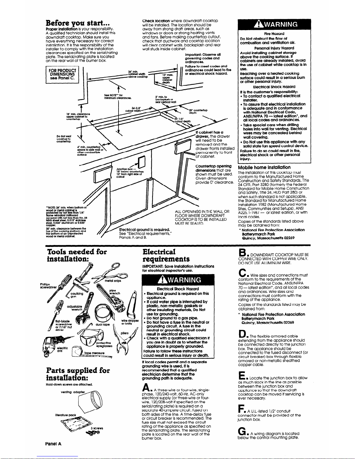
FOR PRODUCT
DIMENSIONS
see Panel C.
See NOTE” for
mlnlmum clearances.
I
2” mln. lo
backsplash of
rear peal wall /
18” mln. clearance
urmer cabIn lo
removed and the
drawer fronts installed
I
Countertop opening
dimensions that are
shown must be used.
Given dimensions
provide 0” clearance.
Mobile home installation
The installation of this cooktop must
conform to the Manufactured Home
Construction and Safety Standards, Title
24 CFR, Part 3280 (formerly the Federal
Standard for Mobile Home Construction
and Safety, Tile 24, HUD Part 280) or
when such standard is not applicable.
the Standard for Manufactured Home
Installation 1982 (Manufactured Home
Sites, Communtties and Setups), ANSI
A225 l-1987 -
or latest edition, or with
local codes.
Copies of the standards listed above
may be obtained from:
l
National Fire Protection Association
Batterymarch Park
Quincy, Massachusetts 02269
“NOTE: 24’ min. when bottom 01~
wyWydrtetal cablnei k
Iii %b”’ less than ‘M
me retar nl mlllboard
covered wllh not less than No. 28
MSG sheet steel. 0.015’ dalnless
deal, 0.024’ aluminum of 0.020
copper.
ALL OPENINGS IN THE WALL OR
FLOOR WHERE DOWNDRAFT
COOK-TOP IS TO BE INSTALLED
MUST BE SEALED.
30’ mln. cleamnce between the
top of the cooking piatiorm and
the bottom of an unpmtecied
wood or metal cabinet.
Panels A and B.
B
w DOWNDRAFT COOK-TOP MUST BE
Tools needed for
Electrical
installation:
requirements
IMPORTANT: Save Installation Instructions
for electrical ins0ector’s use.
CONNECTED WITH COPPER WIRE ONLY.
DO NOT USE ALUMINUM WIRE.
C
n
Wire sizes and connections must
conform to the requirements of the
National Electrical Code, ANSI/NFPA
70 - latest edition*, and all local codes
and ordinances. Wire sizes and
connections must conform with the
rating of the appliance.
Copies of the standards listed may be
obtained from:
l
National Fire Protection Association
Batterymarch Park
Quincy, Massachusetts 02269
- // metal snips
Electrical Shock Hazard
l
Electrical ground is required on this
appliance.
. If cold water pipe is interrupted by
plastic, non-metallic gaskets or
other insulating materials, Do Not
use for grounding.
. Do Not ground to a gas pipe.
l
Do Not have a fuse in the neutral or
grounding circuit. A fuse in the
neutral or grounding circuit could
result in electrfcal shock.
l
Check with a quatttied electrician if
you are in doubt as to whether the
appliance is properly grounded.
Failure to follow these instructions
could result in serious injury or death.
Pipe
wrench
ducttape
or knife
D
n
The flexible armored cable
extending from the appliance should
be connected directly to the junction
box. The appliance should be
connected to the fused disconnect (or
circuit breaker) box through flexible
armored or non-metallic sheathed
copper cable.
L
lf local codes permit and a separate
grounding wire is used, it is
recommended that a qualifred
electrician determine that the
grounding path is adequate.
A
n
A three-wire or four-wire, singlephase, 120/240-volt, &Hz, AC-only
electrical supply (or three-wire or four-
wire, 120/208-volt if specified on the
serial/rating plate) is required on a
separate 40-ampere circuit, fused on
both sides of the line. A time-delay fuse
or circuit breaker is recommended. The
fuse size must not exceed the circuit
rating of the appliance as specified on
the serial/rating plate. The serial/rating
plate is located on the rear wall of the
burner box.
Parts suppIled for
itnstallatgon:
E
n
Locate the junction box to allow
as much slack in the line as possible
between the junction box and
appliance so that the downdraft
cooktop can be moved if servicing is
ever necessary.
Hold-down screws are attached.
F
n
A U.L.-listed l/2” conduit
connector must be provided at the
junction box.
G
w A wiring diagram is located
below the control mounting plate.
Panel A
Page 3

Electrical
connectjron
cable from power supply
J I I
white wires
junctton box
\
requirements
Ductwork needed for installation is not
included.
Electrical Shock Hazard
l
Electrical ground -S required on this
appliance.
l
Do Not connect to the electrical
supply until appliance is
permanently grounded.
l
Disconnect power to the junction
box before making the electrical
connection.
l
This appliance must be connected
to a grounded, metallic, permanent
wiring system, or a grounding
connector should be connected to
the grounding terminal or wire lead
on the appliance.
Failure to do so could result in a fire,
personal injury or electrical shock.
wire
Fire Hazard
. Venting system MUST terminate to the
outside.
l
Do Not terminate the ductwork in an
attic or other enclosed space.
l
Do Not use 4” laundry-type wall caps.
l
Do Not use plastic-type ductwork.
Failure to follow recommended venting
bare) wires
.
/+
&-listed conduit
cable from cooktop
connector
Ungrounded neutral
Figure 2
4. Connect the white wire from the
power supply cable to the neutral
(white) wire in the junction box.
5. Connect the two black wires
together; then connect the red wires
together with wire connectors.
(See Figure 2.)
6. Connect the green (or bare) wire to a
grounded cold water pipe* (or to?he
grounded lead in the service panel).
Do Not ground to a gas supply pipe or
hot wafer pipe. Do Not connect to
electrical supply until appliance is
permanently grounded.
(See Figure 3.)
grounded cold
water pipe
instructions may result in a fire.
Determine which venting method to
use. Ductwork can extend either
through the wall or floor.
The length of the ductwork and number
of elbows should be kept to a minimum
to provide efficient performance.
The size of the ductwork should be
uniform.
Do Not install two elbows together.
Use duct tape to seal all joints in the
ductwork system.
Use caulking tape to seal the exterior
wall or floor opening around the cap.
Do Not cut joist or stud. If ductwork
cutout falls over a joist or stud, a
supporting frame must be constructed.
Flexible metal ductwork is Not
recommended. If it is used, calculate
each foot of flexible ductwork as two
feet of rigid. Flexible elbows count twice
as much as standard elbows. Use metal
ductwork only. Figures 5-8 show
common venting methods and types of
materials needed.
NOTE: Make sure there is proper
clearance within the wall or floor
exhaust duct before making cutouts.
Recommended duct length
Ductwork length should not exceed
the maximum length listed in the
“Maximum length of duct system”
chart. (See Panel C.)
This appliance is manufactured with a
white (neutral) power supply wire and a
frame-connected green (or bare)
grounding wire twisted together.
Connect the appliance cable to the
junction box through the U.L.-listed
conduit connector. Complete electrical
connection according to local codes
and ordinances.
A
n
Where local codes permit...
connecting the frame-grounding
conductor to the neutral (white) junction
box wire:
1. Disconnect the power supply.
2. Connect the flexible armored cable
that extends from the downdraft
cooktop to the junction box using a
U.L.-listed conduit connector. Tighten
the screws on the conduit connector.
3. Connect the neutral (white) wire in
the junction box with the green (or
bare) wire and white wire from the
appliance cable with a wire
connector.
4. Connect the two black wires
together; then connect the two red
wires together with wire connectors,
(See Figure 1.)
cable from power supply
junction box
J
I I
GROUNDED
CLAMP MUST BE
TIGHT ON PIPE
CODDW
No.-4
copper
Tlghren nl
firmly. \
. .
tits
grdlinding wire
/
:+T m
PiF
‘“‘/
be
clamps
Figure 3 .
’ Grounded cold water pipe must have metal
continuity to electrical ground and not be
interrupted by plastic, rubber, or other
electrlcally insulating connectors, such as hoses,
fittings, washers or gaskets (including water
meter or pump). Any electrical insulating
connector should be jumped as shown with a
len 3 th
of No-4 wlre securely clamped to bare
me al
at both ends.
Through the wall installation
Outside wail locatlon
’ housing
black wire
twist-on
con/nectar
C
m If connecting to a four-wire
electrical system:
1. Disconnect the power supply.
2. Connect the flexible armored cable
that extends from the downdraft
cooktop to the junction box using a
U.L.-listed conduit connector. Tighten
the screws on the conduit connector.
3. Separate the white wire from the
green (or bare) wire that extends out
the end of the appliance cable. (See
figure 4.)
4. Connect the white wires together;
connect the red wires together; then
connect the black wires together with
wire connectors.
5. Connect the green (or bare)
grounding wire from the appliance
cable to a grounding wire in the
junction box.
cable tram power supply
Figure 5 ’
bare) wire
U.i.-list@ conduit
cable-tram cooktop
Grounded neutral
Figure 1
B B
n
Where local codes Do Not
n
Where local codes Do Not
permit...
connecting the frame-
permit...
connecting the framegrounding conductor to the neutral grounding conductor to the neutral
(white) junction box wire: (white) junction box wire:
Figure 6
Through the floor installation
island location
junction box
white wires
black
wire
1. Disconnect the power supply.
2. Connect the flexible armored cable
that extends from the downdraft
cooktop to the junction box using a
U.L.-listed conduit connector. Tighten
the screws on the conduit connector.
3. Separate the white wire from the
green (or bare) wire that extends out
the end of the appliance cable. (See
Figure 2.)
reen (or
&Y
re) wires
A
d
cable from c&ktop
connector
Figure 4
I
4
Figure 7
Panel B
Page 4

. .._..... -
-.
-haust vent
5-314’Irom
centerline of
vent to front
edge of cutout
Figure 8
Recommended duct length for
island or peninsula installations
Use round 6” or 3-l/4” x 10” duct with a
maximum of 26 feet for duct system. For
best performance, use no more than
three 90” elbows. Do Not install two
elbows together.
Determining the length of system
you need.
To calculate the length of system you
need, add the equivalent feet for each
duct piece that will be needed. See the
following examples.
6’ duct system
90” elbows
(3JjFj
Maximum length = 26 ft.
2 - 90” elbows
= loft.
1 -surface wall cap
= Oft.
8 feet straight
= 8ft.
Length of 6” system
= 18ft.
Recommended standard finings
6’ systems: equivalent length of 6’ duct
I
3-l/4’ x 10’ to
I
3-y/4’ x lo’ to 6’
I
6’ to 3-114’ x 10
6’ = 4.5 ft.
900 mow = 5 ft.
9o”ebow=9ft.
3-l/4’ x 10’ duct system
&l $“&W
0
k-6ft.-
k
6’to3-l/&x
10’ transition
m length = 20 ft.
1 - 90” elbow
= 5ft.
1 - wall cap
= Oft.
1 - 6” to 3- l/4”
x 10” transition
= 6ft.
8 feet straight
= 8f-t.
Length of 3- l/4” x 10” system
= 19ft.
Recommended standard fittings
3-114’ systems: equivalent length d 3-114 x 10” duct
6 to 3-l/4’ x 10
6’ to 3-l/4’ x 10
9o’elbow =9ft.
= i n.
3-114’ x lo’ flat
elbow = 12 tt.
3-l/Cx lo’ wall
cap=ofi.
Now start...
I
Cut metal band from around
, the top flange of carton and
remove the top of carton.
Filters located here.
2
Remove the foam pads and
. cooktop from carton. Remove
foam pads from front and back
of cooktop. Remove any tape from
cooktop, including tape holding filters
inside the appliance.
3
Install venting adapter to blower
w housing using three screws
provided. Rotate the blower
housing downward to clear the cabinet
opening.
hold-down bolt
4
Insert the downdraft cooktop
n
into the countertop cutout.
Check that front edge of
downdraft cooktop is parallel to front
edge of countertop and at least 1- l/2
inches back from front edge of
countertop and 2 inches from any
vertical walls. Tighten hold-down bolts a-t
each side of unit.
5
Connect vent adapter to
n
installed venting system. See
“Venting requirements,” Panels
B and C.
6
Make electrical connections.
n
See “Electrical requirements”
and “Electrical connection”
sections,” Panels A and B.
7
Install modules in cooktop
w following instructions in Use and
Care Guide.
8
Turn power supply on. Check
. that grill, module and vents are
operating correctly. If one does
not operate, disconnect the power
source and check that wire
connections have been made
correctly.
your new Whirlpool
downdraft cooktop. To get the
most efficient use from your new
downdraft cooktop, read your
Whirlpool Use and Care Guide.
1 Congratulations! 1
Keep Installation Instructions and
Guide close to downdraft cooktop
for easy reference. The
instructions will make
reinstalling
Numbers
correspond
to steps.
Panel C
Page 5

If the downdraft
cooktop does not
operate...
l
Check that the circuit breaker is not
tripped or the house fuse blown.
l
See Use and Care Guide for
troubleshooting checklist.
NOTE: Refer t& Use and care
GIJI~&~
and cleaning
I
If you need
assistance...
The Whirlpool Consumer Assistance
Center will answer any questions about
operating or maintaining your cooktop
not covered in the Installation
Instructions. The Whirlpool Consumer
Assistance Center is open 24 hours a
day, 7 days a week. Just dial
l- (800) 253-1301
-the call is free.
When you call, you will need the
cooktop model number and serial
number. Both numbers can be found on
the serial/rating plate loccrted on the
rear wall of the burner box.
Vkffl 01
4a
C-
Part No. 36-309208-02-O/1 4363133 Rev. A
0
1993
Whirlpool Corporation
Prepared by Whirlpool Corporation, Benton Harbor, Michigan 49022
Prlnted In U.S.A.
If you need
servke...
In the event that your Whirlpool
appliance should need service, call the
dealer from whom you purchased the
appliance or a Whirlpool-authorized
service company. A Whirlpoolauthorized service company is listed in
the Yellow Pages of your telephone
directory under “Appliances Household
- Major - Service or
Repair’. You can also obtain the service
company’s name and telephone
number by dialing, free, within the
continental United States, the Whirlpool
Consumer Assistance Center telephone
number, l-(800) 253-1301. A special
operator will tell you the name and
number of your nearest Whirlpoolauthorized service company.
Maintain the quality built into your
Whirlpool appliance--call a Whirlpoolauthorized service company.
Prlnted on recycled paper.
10% post consumer waste/
50% recovered materials.
 Loading...