

Maytag 3405344 Installation Manual
Have questions about your dryer?
Check your Use and Care Guide for a toll-free number to call, or call your
dealer. The dealer is listed in the Yellow Pages of your phone directory
under “Appliances - Household - Major - Service and Repair.”
When you call, you will need the dryer model number and serial number.
Both numbers are on the model/serial rating plate located in the door well
behind the dryer door and on front of openinq.
Record the numbers here for handy reference:
I -
Model No.
Serial No.
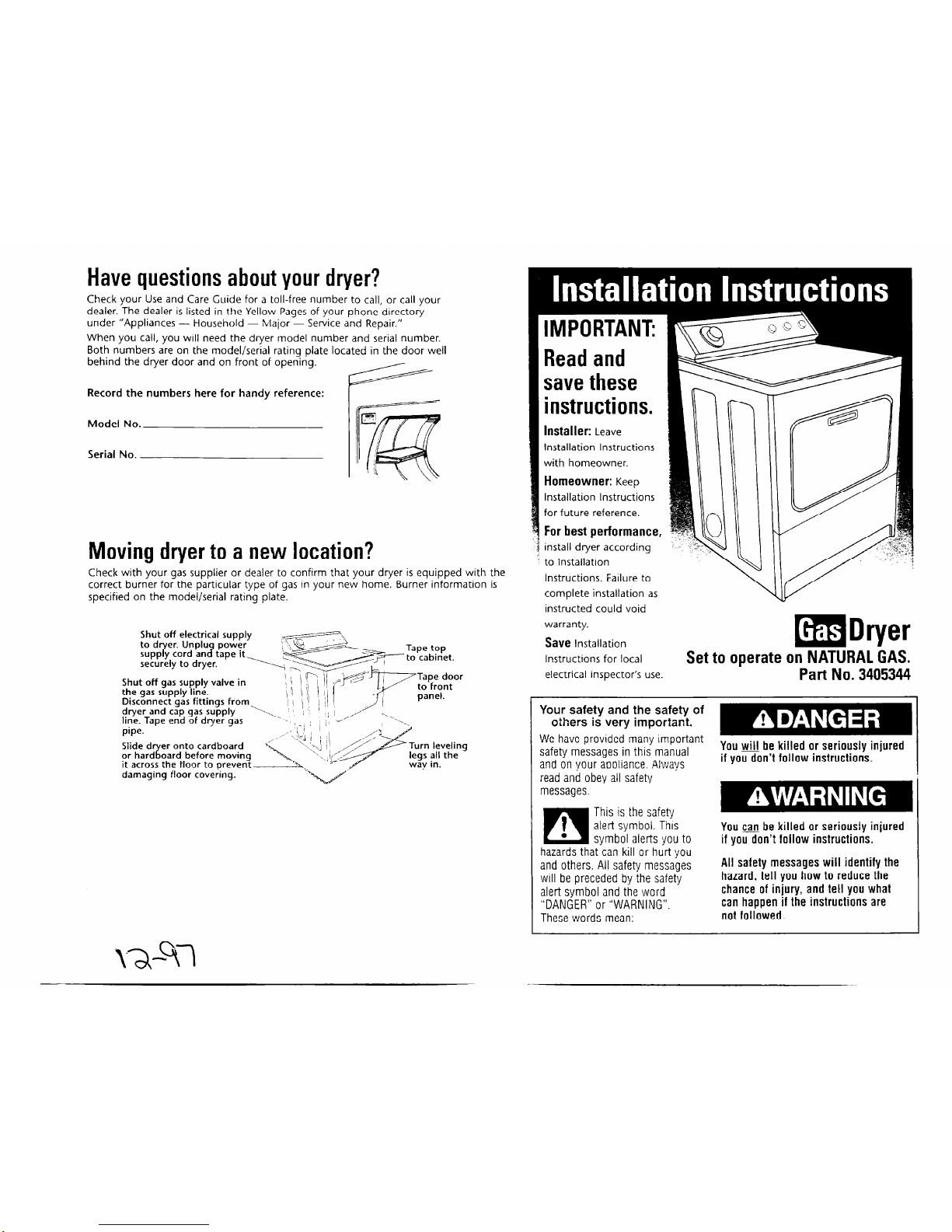
Moving dryer to a new location?
Check with your gas supplier or dealer to confirm that your dryer is equipped with the
correct burner for the particular type of gas in your new home. Burner information is
specified on the model/serial rating plate.
Shut off electrical supply
.~ \
Shut off gas supply valve in
the gas
supply line.
Disconnect gas fittings from
dryer and cap gas supply
line. Tape end of dryer gas
pipe.
Tape
door
to front
panel.
oard before moving
it across the floor to orevent
damaging floor covekng.
IMPORTANT:
Read and
save these
instructions.
Installer:
Leave
Installation Instructions
with homeowner.
Homeowner:
Keep
Installation Instructions
for future reference.
For best performance,
install dryer according
to Installation
Instructions. Failure to
complete installation as
instructed could void
warranty.
Save
Installation
mDryer
Instructions for local
Set to operate on NATURAL GAS.
electrical inspector’s use.
Part No. 3405344
Your safety
and the safety
of
others is very important.
We have provided many important
safety messages in this manual
You will be killed or seriously injured
and on vour aooliance. Always
if you don’t follow instructions.
1 read and obey all safety
ges. messal
m This is the safety
Ifi
t
.
alert symbol. This
svmbol alerts you to
hazards that-can kill or h&t you
and others. All safety messages
will be preceded by the safety
alert symbol and the word
“DANGER” or “WARNING”.
These words mean:
You cafe be killed or seriously injured
if YOU don’t follow instructions.
-
All safety messages will identify the
hazard, tell you how to reduce the
chance of injury, and tell you what
can happen if the instructions are
not followed.
mm
rm I l
I
a
WARNING: If the information in this
manual is not followed exactly, a fire
or explosion may result causing
property damage, personal injury or
death.
- Do Not store or use gasoline,
or other flammable vapors and
liquids in the vicinity of this or any
other appliance.
- WHAT TO DO IF YOU SMELL GAS:
l
Do Not try to light any appliance.
l
Do Not touch any electrical switch;
Do Not use any phone in your
building.
l
Immediately call your gas supplier
from a neighbor’s phone. Follow ga!
supplier’s instructions.
l
If you cannot reach your gas
supplier, call the fire department.
- Installation and service must be
done by a qualified installer, service
agency or the gas supplier.
Check that you have everything necessary for correct
installation. Proper installation ig your responsibility.
1 Tools needed:
l
8” or lo” pipe wrench
l
8” or 10" adjustable
wrench (for gas
connections)
l
flat-blade screwdriver
l
adjustable wrench that
opens to 1” or 1” hexhead socket wrench (for
adjusting dryer feet)
l level
l
safety glasses
Part No. 3405344
0 1997
l
pipe-joint compound
resistant to
L.P.
gas
l
caulking gun and
compound (for installing
new exhaust vent)
l gloves
l
pliers
l
putty knife
l
tin snips (new vent
installations)
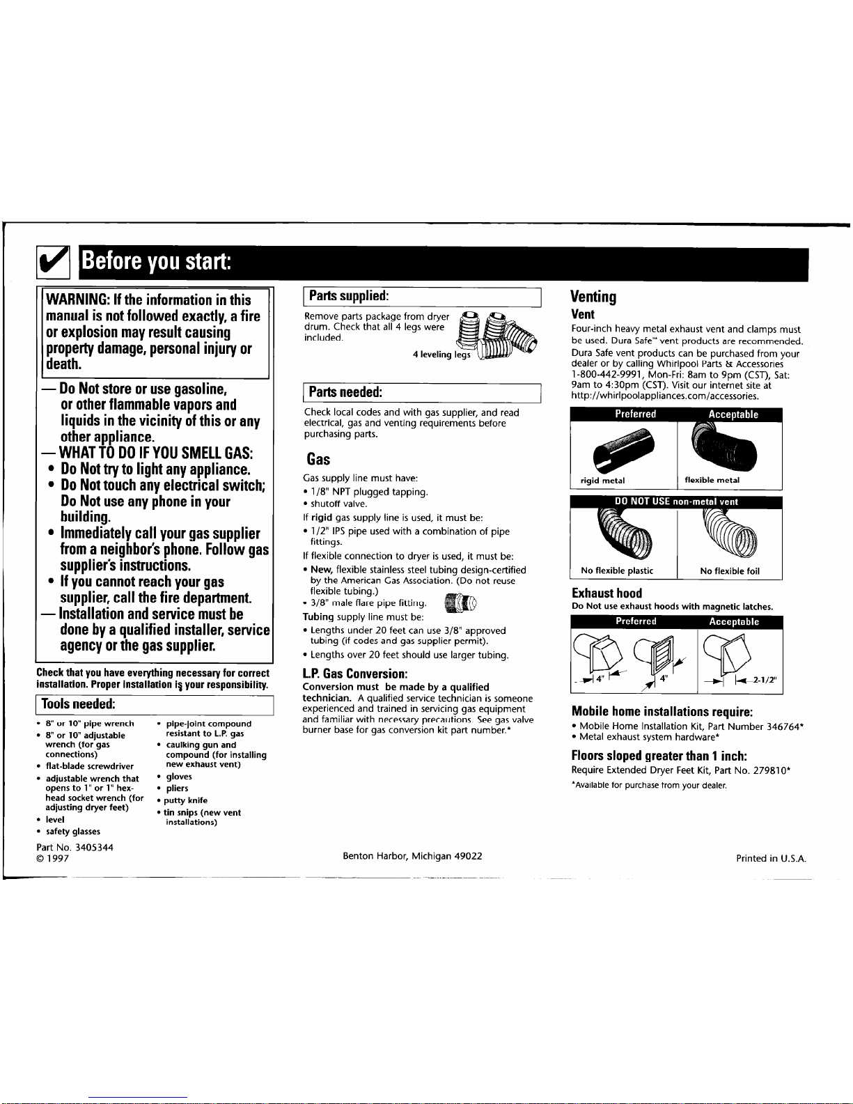
1 Parts supplied:
Remove parts package from dryer
drum. Check that all 4 legs were
included.
4 leveling I
1 Parts needed:
Check local codes and with gas supplier, and read
electrical, gas and venting requirements before
purchasing parts.
Gas
Gas supply line must have:
l
l/8” NPT plugged tapping.
l
shutoff valve.
If rigid gas supply line is used, it must be:
l
l/2” IPS pipe used with a combination of pipe
fittings.
If flexible connection to dryer is used, it must be:
l
New, flexible stainless steel tubing design-certified
by the American Gas Association. (Do not reuse
flexible tubing.)
l
3/8” male flare pipe fitting.
Tubing supply line must be:
. Lengths under 20 feet can use 318” approved
tubing (if codes and gas supplier permit).
l
Lengths over 20 feet should use larger tubing.
L.P. Gas Conversion:
Conversion must
be made by a qualified
technician.
A qualified service technician is someone
experienced and trained in servicing gas equipment
and familiar with necessary precautions. See gas valve
burner base for gas conversion kit part number.*
Benton Harbor, Michigan 49022
Venting
Vent
Four-inch heavy metal exhaust vent and clamps must
be used. Dura Safe’” vent products are recommended.
Dura Safe vent products can be purchased from your
dealer or by calling Whirlpool Parts & Accessories
l-800-442-9991, Mon-Fri: 8am to 9pm (CST), Sat:
9am to 4:30pm (CST). Visit our internet site at
http://whirlpoolappliances.com/accessories.
rigid metal
flexible metal
I
No flexible plastic
Exhaust hood
No flexible foil
Do Not use exhaust hoods with magnetic latches,
Mobile home installations require:
l
Mobile Home Installation Kit, Part Number 346764*
l
Metal exhaust system hardware*
Floors sloped greater than 1 inch:
Require Extended Dryer Feet Kit, Part No. 279810*
*Available for purchase from your dealer.
Printed in U.S.A.
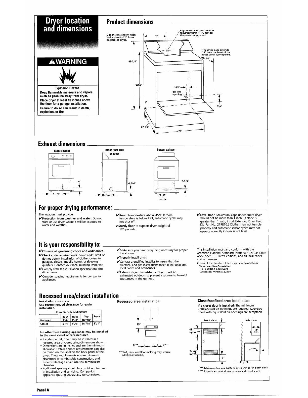
Product dimensions
A grounded electrical outlet is
required within 4-l/2 feet for
the power supply cord.
Dimensions shown with
feet extended 1” from
bottom of dryer.
Explosion Hazard
Keep flammable materials and vapors,
such as gasoline away from dryer.
Place dryer at least 18 inches above
the floor for a garage installation.
Failure to do so can result in death,
explosion, or fire.
Exhaust dimensions
27-112”
back exhaust
left or right side
c
bottom exhaust
I
I
For proper drying performance:
The location must provide:
C/Protection from weather and water:
Do not
store or use dryer where it will be exposed to
water and weather.
)/Room temperature above 45°F:
If room
temperature is below 45”F, automatic cycles may
not shut off.
/Sturdy floor
to support dryer weight of
120 pounds.
(/Level floor:
Maximum slope under entire dryer
should not be more than 1 inch. (If slope is
greater than 1 inch, install Extended Dryer Feet
Kit, Part No. 279810.) Clothes may not tumble
properly and automatic sensor cycles may not
operate correctly if dryer is not level.
It is your responsibility to:
(/Observe all governing codes and ordinances.
/Check code requirements:
Some codes limit or
do not permit installation of clothes dryers in
garages, closets, mobile homes or sleeping
quarters. Contact your local building inspector.
/Comply with the installation specifications and
dimensions.
(/Consider spacing requirements for companion
appliances.
)/Make sure you have everything necessary for proper
installation.
L/Properly install dryer.
)/Contact a qualified installer to insure that the
electrical and gas installations meet all national and
local codes and ordinances.
L/Exhaust dryer to outdoors:
Dryer must be
exhausted outdoors to prevent exposure to harmful
substances in the gas fuel.
This installation must also conform with the
American National Standard, National Fuel Gas Code
ANSI 2223.1 - latest edition*, and all local codes
and ordinances.
Copies of the standards listed may be obtained from:
*American Gas Association
1515 Wilson Boulevard
Arlington, Virginia 22209
Recessed area/closet installation
Use recommended clearance for easier
Installation clearances
installation.
Recommended/Minimum
Recessed area installation
If a closet door is installed:
The minimum
Closet/confined area installation
unobstructed air openings are required. Louvered
doors with equivalent air openings are acceptable.
Recessed
Closet
Back
Sides Top Front
y!,o” , “,o”
18”/18” -
yv,4” 1 “/o”
18”/18” l”/l”
No other fuel burning appliance may be installed
in the same closet or recessed area.
l
If codes permit, dryer may be installed in a
recessed area or closet using dimensions shown.
l
Dimensions are in inches and are the minimum
allowable. Detailed space requirements can also
be found on the label on the back panel of the
dryer. These requirements ensure minimum
clearances to combustible construction, and
prevent blockage of air into the combustion
chamber.
** Walj,, door and floor molding may require
addrtronal spacing.
l
Additional spacing should be considered for ease
of installation and servicing. Companion
appliance spacing should also be considered.
front view
side view
t
a-
sq. in.***
t
0
*** Minimum top and bottom air openings for closet door
**** External exhaust elbow requires additional space.
Panel A
 Loading...