

Maytag 3397600 Installation Manual
IMPORTANT:
Read and save
these instructions.
IMPORTANT:
Installer: Leave Installation Instructions
with the homeowner.
Homeowner: Keep Installation Instructions
for future reference.
Save Installation Instructions for local
electrical inspector’s use.
~.-
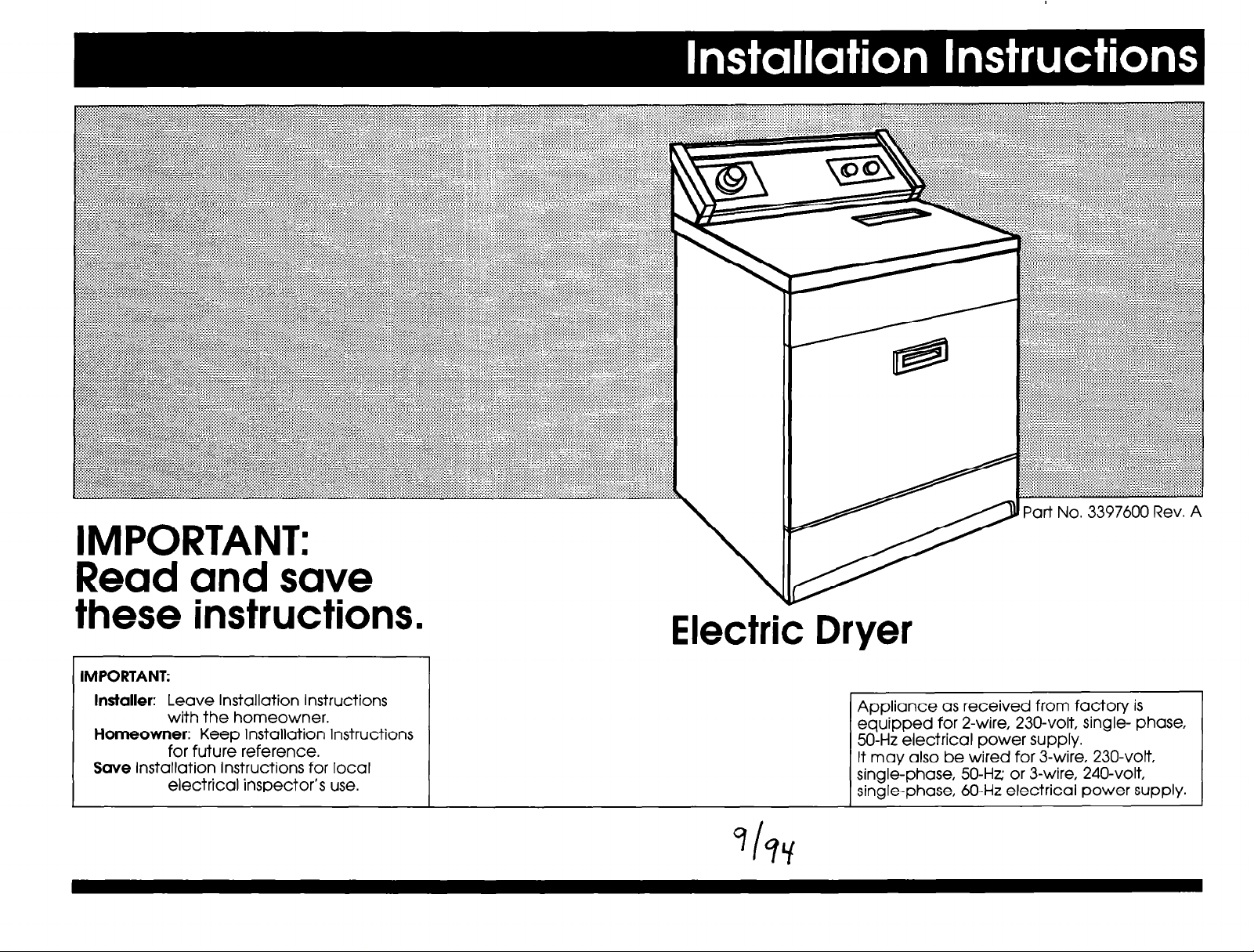
Electric Dryer
Appliance as received from factory is
equipped for 2-wire, 230-volt, single- phase,
50-Hz electrical power supply.
It may also be wired for 3-wire, 230-volt,
single-phase, 50-Hz or 3-wire, 240-volt,
single-phase, 60-Hz electrical power supply.
L
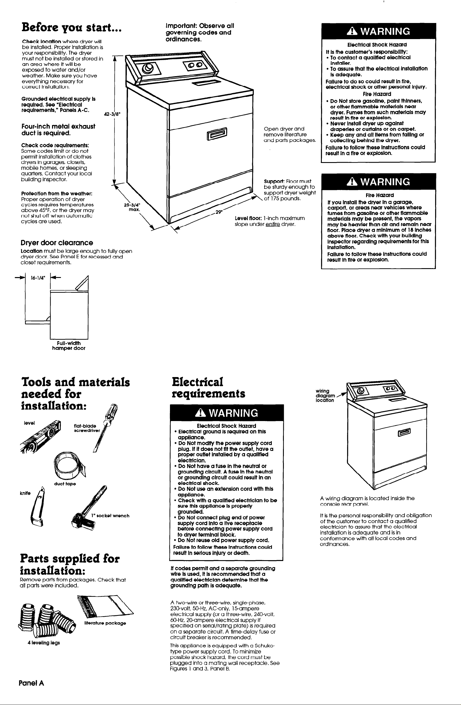
Before you start...
Check location
be installed. Proper Installation is
your responsibility. The dryer
must not be installed or stored in
an area where It will be
exposed to water and/or
weather. Make sure you have
everything necessary for
correct installation.
Grounded electrlcal supply Is
required. See ‘ElectrIcal
requlrements,” Panels A-C.
Four-inch metal exhaust
duct is required.
Check code requirements:
Some codes limit or do not
permit installation of clothes
dryers in garages, closets,
mobile homes, or sleeping
quarters. Contact your local
buildlng inspector.
Protectlon from the weather:
Proper operation of dryer
cycles requires temperatures
above 45°F. or the dryer may
not shut off when automatic
cycles are used.
Dryer door clearance
Locatlon
dryer door. See Panel E for recessed and
closet requirements.
must be large enough to fully open
where dryer will
42-
3)
8”
Important: Observe all
governing codes and
ordinances.
Open dryer and
remove literature
and parts packages.
Support:
be sturdy enough to
support dryer welght
z of 175 pounds,
Floor must
Electrlcal Shock Hazard
It Is the customer’s responslblllty:
l
To contact a quallfled electrlcal
Installer.
. To assure that the electrlcal lnstallatlon
Is adequate.
Failure to do so could result In tlre,
electrlcal shock or other personal Injury.
Fire Hazard
l
Do Not store gasoline, palnt thinners,
or other tlammable materials near
dryer. Fumes tram such materials may
result In tire or exploslon.
l
Never Install dryer up agalnst
draperies or curtalns or on carpet.
. Keep any and all Items tram talllng or
collecting behlnd the dryer.
Failure to tallow these lnstructlons could
result In a fire or exploslon.
Fire Hazard
lt you Install the dryer In a garage,
carport, or areas near vehicles where
fumes tram gasoline or other tlammable
materials may be present, the vapors
may be heavier than alr and remain near
floor. Place dryer a mlnlmum ot 18 Inches
above tloor. Check wlth your bulldlng
Inspector regarding requlrements tar thls
Installation.
Failure to follow these lnstructlons could
result In flre or explosion.
Full-wldth
hamper door
Tools and materials
needed for
hstallation:
kniie
“socket wrench
Parts supplied for
installation:
Remove parts from packages. Check that
all parts were included.
Electrical requirements
Electrlcal Shock Hazard
l
Electrlcal ground Is required on thls
appliance.
l
Do Not modlty the power supply cord
plug. It It does not tlt the outtet, have a
proper outlet Installed by a qualltled
electrlclan.
l
Do Not have a tuse In the neutral or
groundlng clrcult. A tuse In the neutral
or grounding clrcult could result In an
electrlcal shock.
l
Do Not use an extension cord wlth thls
appliance.
l
Check wlth a qualltled electrlclan to be
sure ltils appliance Is properly
grounded.
l
Do Not connect plug end ot power
supply cord Into a live receptacle
before connecting power supply cord
to dryer terminal block.
l
Do Not reuse old power supply cord.
Failure to kllow these Instructions could
result In serious Injury or death.
lt codes permit and a separate groundlng
wire Is used, It Is recommended that a
quallfled electrlclan determlne that the
groundlng path Is adequate.
A wiring diagram is located inside the
console rear panel.
It is the personal responsibility and obligation
of the customer to contact a qualified
electrlcian to assure that the electrical
installation is adequate and is in
conformance with all local codes and
ordinances.
4 leveling legs
Panel A
literature package
A two-wire or three-wire, single-phase,
23Dvolt, 50-Hz, AC-only, 1 Sampere
electrical supply (or a three-wire, 240-volt,
60-Hz, 20-ampere electrical supply if
specified on serial/rating plate) is required
on a separate circuit. A time-delay fuse or
circuit breaker is recommended.
This appliance is equipped with a Schukotype power supply cord. To minimize
possible shock hazard, the cord must be
plugged into a mating wall receptacle. See
Figures 1 and 3, Panel B.
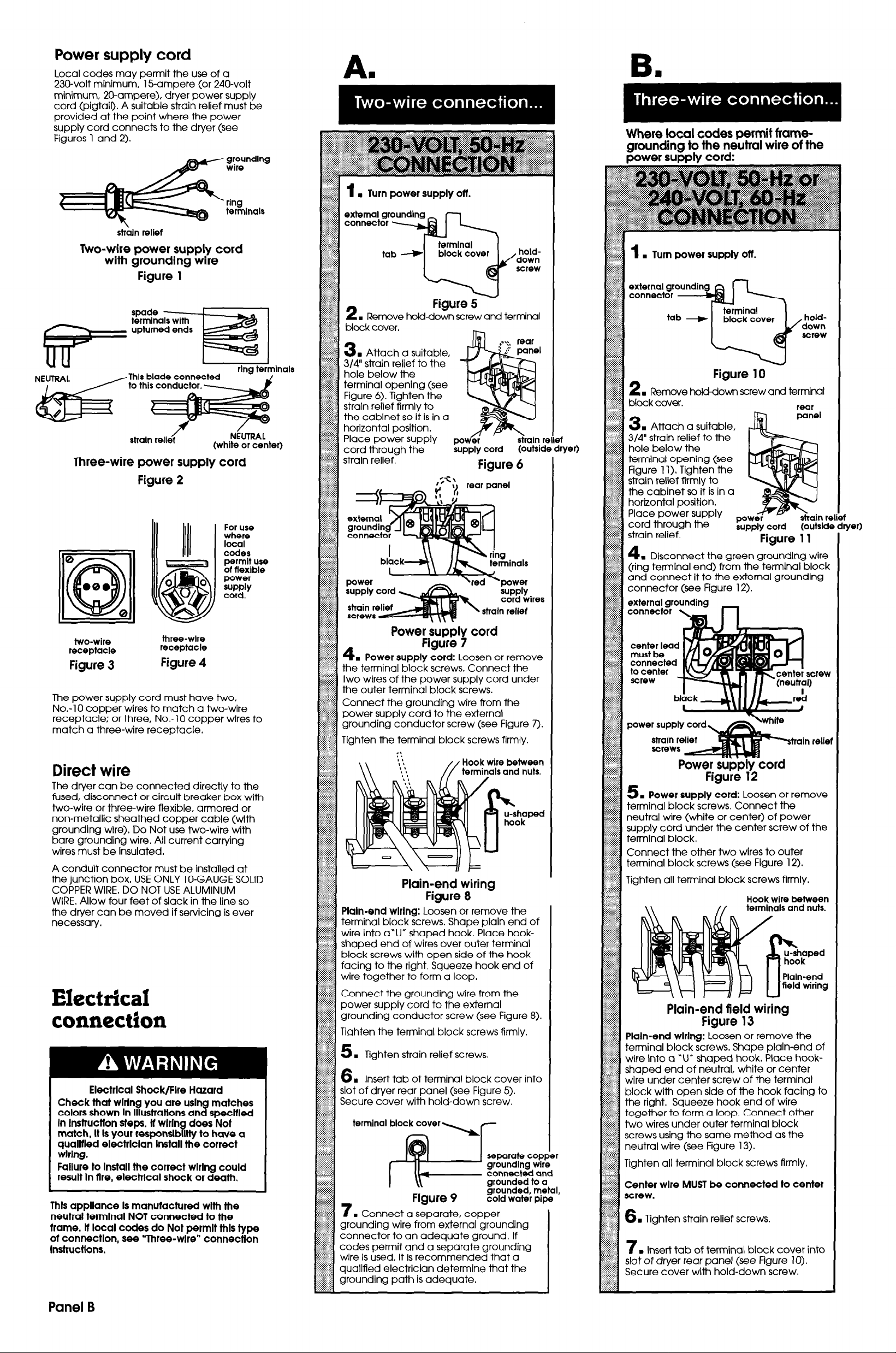
Power supply cord
Local codes may permit the use of a
230-volt minimum, 15-ampere (or 240-volt
minimum, 20-ampere), dryer power supply
cord (pigtail). A suitable strain relief must be
provided at the point where the power
supply cord connects to the dryer (see
Figures 1 and 2).
grounding
wire
strbln relief
Two-wire power
with grounding wire
Figure 1
strain reliec
Three-wire power
Figure 2
supply
supply
cord
NiUl’RAL
(white or center)
cord
For use
where
local
codes
permit use
of flexible
power
SwPlY
cord.
inals
1
. Turn power supply off.
tab --t
Figure 5
2
. Remove holddown screw and terminal
block cover.
. Attach a suitable,
3
3/B” strain relief to the
hole below the
terminal opening (see
Figure 6). Tighten the
strain relief firmly to
the cabinet so it is in a
horizontal position.
Place power supply
cord through the
strain relief.
~ppiy cord
Figure 6
,;c\
1 rear panel
&bply
cord wires
strain relief
holddown
screw
(outsids
Ilie
,d
Where local codes permit framegrounding to the neutral wire of the
Dower surmlv cord:
1
. Turn power supply ott.
holddown
screw
Figure 10
. Remove hold-down screw and terminal
2
block cover.
. Attach a suitable.
3
3/4” strain relief to the
hole below the
terminal opening (see
Figure 11). Tighten the
strain relief firmly to
the cabinet so it is in a
horttontal position.
Place power supply
cord through the
strain relief.
4
. Disconnect the green groundlng wire
(ring termlnal end) from the terminal block
and connect it to the external grounding
connector (see Figure 12).
external grounding
connector \,
supply cord (outsldc
Figure 11
rear
two-wire
receptacle
Figure 3
The power supply cord must have two,
No.-10 copper wires to match a two-wire
receptacle; or three, No.-1 0 copper wires to
match a three-wire receptacle.
three-wlre
receptacle
Figure 4
Direct wire
The dryer can be connected directly to the
fused, disconnect or circuit breaker box with
two-wire or three-wire flexible, armored or
non-metallic sheathed copper cable (with
grounding wire). Do Not use two-wire with
bare groundlng wire. All current carrying
wires must be Insulated.
A conduit connector must be installed at
the junction box. USE ONLY lo-GAUGE SOLID
COPPER WIRE. DO NOT USE ALUMINUM
WIRE. Allow four feet of stack in the line so
the dryer can be moved if servicing is ever
necessary.
Power SUDDIV cord
1
4. Power supply cord:
the terminal block screws. Connect the
two wires of the power supply cord under
the outer terminal block screws.
Connect the grounding wire from the
power supply cord to the external
grounding conductor screw (see Figure 7).
Tighten
fie terminal block screws firmly.
Loosen or remove
Hook wire
between
Plain-end wiring
plaInmend
terminal block screws. Shape plain end of
wire into a”U” *aped hook. Place hook-
shaped end of wires over outer terminal
block screws with open side of the hook
wiring:
Loosen or remove the
connected
to center
screw
power supply cord
train relic
Figure 12
. Power supply cord:
5
terminal block screws. Connect the
neutral wire (white or center) of power
ther two wires to outer
screws (see Figure 12).
inal block screws firmly.
Loosen or remove
:rew
Electrical connection
Electrlcal Shock/Fire Hazard
Check that wlrlng you are using matches
colors shown In lllustratlons and specltled
In lnstructlon steps. lf wlrlng does Not
match, It ls your responslblllty to have a
qualltled electrlclan Install the correct
wlrlng.
Failure to Install the correct wlrlng could
result In flre, electrlcal shock or death.
I
This appliance Is manutactured wlth the
neutral terminal NOT connected to the
trame. lt local codes do Not permit thls type
ot connectlon, see “Three-wire” connection
Instructions.
1
wire together to form a loop,
Connect the
power supply cord to the external
grounding conductor screw (see Figure 8).
Tighten
5
. Tighten strain relief screws.
6
. Insert tab of terminal block cover into
slot of dryer rear panel (see Figure 5).
Secure cover with hold-down screw.
terminal
7
. Connect a separate, copper
grounding wire from external grounding
connector to an adequate ground, If
codes permit and a separate grounding
wire is used, it is recommended that a
qualified electrician determine that the
grounding path is adequate.
grounding
the terminal block screws
Figure 9
wire from +he
separate copper
groundlng wire
connected and
grounded to a
grounded, metal,
cold water pipe
firmly.
. Tighten strain relief screws.
6
. Insert tab of terminal block cover into
7
slot of dryer rear panel (we Figure 10).
Secure cover witi hold-down screw,
Panel B
 Loading...