

Maytag 3395316 Installation Manual
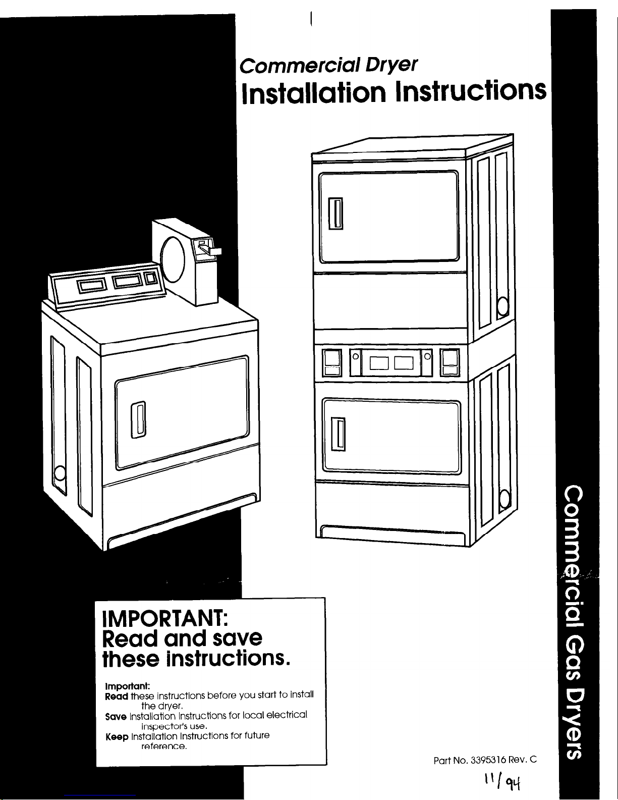
Commercial Dryer
Installation Instructions
MPORTANT:
?ead and save
lhese instructions.
Important:
Read
these instructions before you start to install
the dryer.
Save
Installation Instructions for local electrical
inspector’s use.
Keep
Installation Instructions for future
reference.
J
Part No. 3395316 Rev. C

Before you start...
Check locatlon
where dryer will be
used. Proper installation is your
responsibility. The dryer must not be
installed or stored in an area where it
will be exposed to water and/or
weather. Make sure you have
everything necessary for correct
installation.
Copies of the
standards
listed above may
be obtained from:
‘American Gas Association
1515 Wilson Boulevard
Arlington, Virginia 22209
l
* National Fire Protection Association
Batterymarch Park
Quincy, Massachusetts 02269
Fire Hazard
For your safety, the Information In
thls manual must be followed to
mlnlmlze the rlsk of flre or exploslon
3r to prevent property damage,
Dersonal InJury or loss of life.
. Do Not store or use gasoline or
other flammable vapors and
llqulds In the vlclnlty of this or any
other appliance.
. WHAT TO DO IF YOU SMELL GAS:
. Do Not try to light any
appliance.
l
Do Not touch any electrlcal
switch; Do Not use any phone
In your bulldlng.
l
Clear the room, bulldlng or area
of all occupants.
9 lmmedlately call your gas
suppller from a nelghbor’s
phone. Follow the gas suppller’s
Instructlons.
. If you cannot reach your gas
suppller, call the flre department.
- Never Install dryer up agalnst
draperies or curtains or on carpet.
. Keep any and all Items from klllng
or collecting behlnd the dryer.
nstallatlon and service must be
Defformed by CI quallfled Installer,
iervlce agency or the gas suppller.
Post this warnlng In a promlnent
locatlon.
It is recommended that the operator
post, in a prominent location,
instructions for the customer’s use in
the event that the customer smells
gas. This information should be
obtained from your local gas supplier.
Protectlon from weather:
Proper
operation requires temperatures
above 45°F (7.2%).
The wiring diagram is located on
inside of the access panel.
Check utllltles:
Proper
f
Important: Observe all governing
codes and ordinances.
Failure to meet codes and
ordinances could lead to fire
or electrical shock.
the
w
supply connections
must be available.
Ill
1 i8-l&G NPT plugged
tapplng Is required.
:l:lj:: s’.::.‘i:j:i$: i requirements, ” Page 3 ,
: . . .
exhausted from
bottom, rear, left
or right side. See
m Exhaust
requirements,”
Fded electrlcal outlet
is
required. See “Electrical
requirements.’ Page 4.
support the total weight of 160 pounds
Level floor:
Maximum floor slope under
dryer- 1 inch.
per dryer; 3 15 pounds for stacked dryers.
recessed area requirements and
product dimensions.
Locatlon
must be large enough to
fully open dryer door. See Page 9 for
Fire Hazard
l
Replace access pcmel before
operatlng dryers.
l
lf you Install dryers ln a garage,
carport, or areas near vehicles
where fumes from gasoline or other
vapors may be present, the vapors
may be heavier than alr and
remain near the floor. Place dryers
a mlnlmum of 18 Inches above
floor. Check wlth your bulldlng
Inspector regardlng requirements
for thls Installation.
:allure to follow these lnstructlons
:ould result In a llre or exploslon.
Electrlcal Shock Hazard
It Is the customer’s responslblllty:
l
To contact a licensed electrlclan.
l
To have dryers Installed
according to all natlonal and
local codes and ordinances.
Failure to do so could result In a flre,
electrlcal shock or other personal
InJury.
Personal InJury Hazard
More than one person Is required to
IIR, tilt, or move the dryers because
of their welght and size.
Failure to follow these lnshuctlons
may result In personal InJury.
Page 2
Tools and
matetials needed
for installation:
adjustable wrench
level
utility knife
pliers
Phillips screwdriver
duct tape
flat-blade screwdriver I” socket wrench
Gas supply
requirements
Fire Hazard
l
These dryers must be connected
to a regulated gas supply.
Failure to do so could result In hlghpressure gas release, resulting In a
flre or exploslon.
l
Have L.P. gas checked by a
quallfled person before lnstalllng
the dryer. The L.P. gas supply must
not exceed a pressure
0r
13”
water column.
. New flexible tublng should be
used. Reuslng old, flexible tublng
mlght result In possible leaks or
flre hazard.
Failure to follow these lnstructlons
could result In fire or exploslon.
OBSERVE ALL GOVERNING CODES
AND ORDINANCES.
w This installation must conform
with American National Standard,
National Fuel Gas Code ANSI 2223.1
- latest edition, and all local codes
and ordinances.
B
n
The desian of this drver has
been certified byThe American Gas
Association for use at altitudes up to
10,000 feet above sea level at the
B.T.U. rating indicated on the
model/serial plate. Burner input
adjustments are not required when
the dryer is operated up to this
elevation.
When installed above 10,000 feet, a
four percent (4%) reduction of the
burner B.T.U. rating shown on the
model/serial plate is required for
each 1,000 foot increase in elevation,
For assistance when converting to
other gas types and/or installing
above 1 O,ooO feet elevation, contact
your local service company.
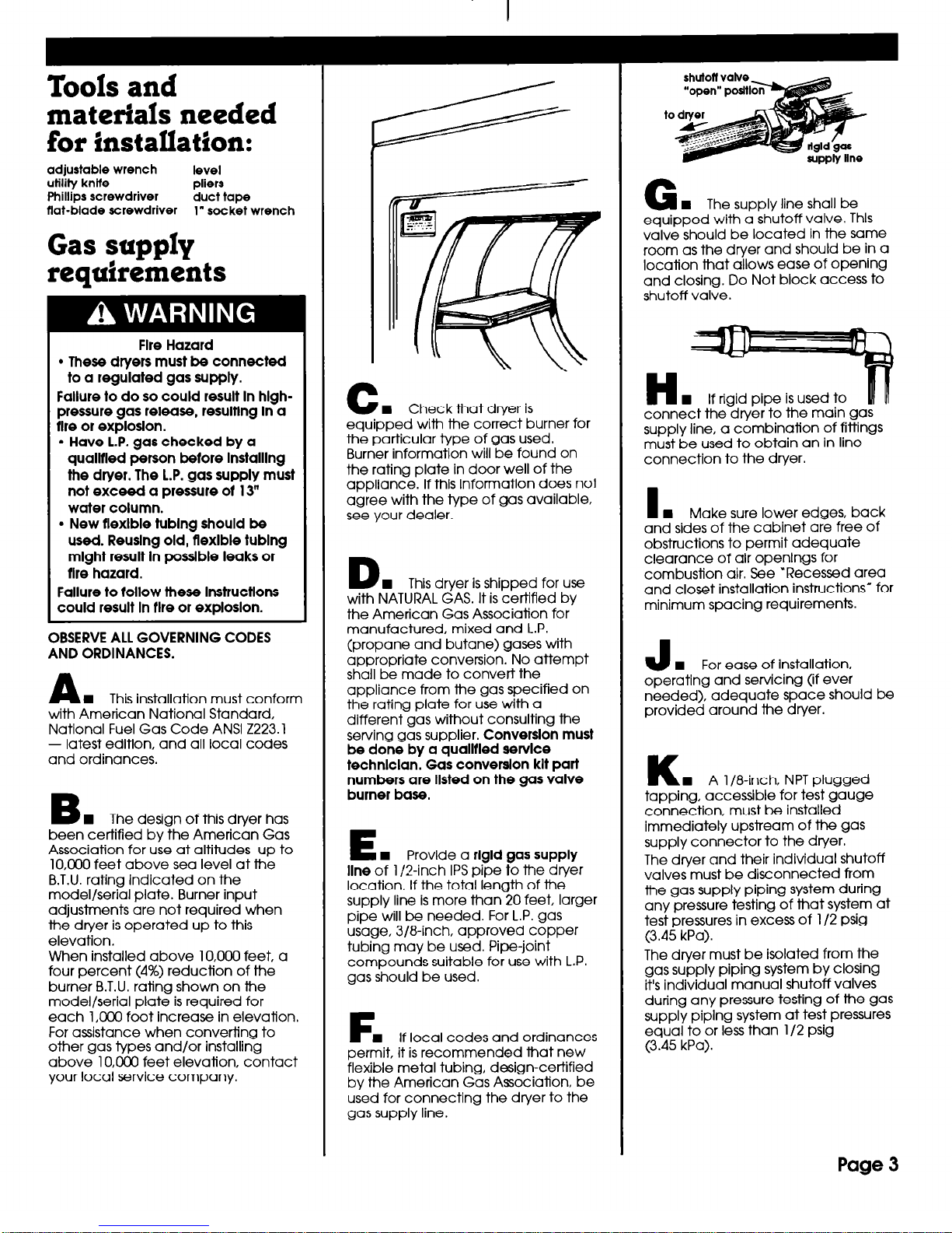
C
w Check that dryer is
equipped with the correct burner for
the particular type of gas used.
Burner information will be found on
the rating plate in door well of the
appliance. If this information does not
agree with the type of gas available,
see your dealer.
D
n
This dryer is shipped for use
with NATURAL GAS. It is certified by
the American Gas Association for
manufactured, mixed and L.P.
(propane and butane) gases with
appropriate conversion. No attempt
shall be made to convert the
appliance from the gas specified on
the rating plate for use with a
different gas without consulting the
serving gas supplier.
Converslon must
be done by a quallfled servlce
technlclan. Gas converslon klt part
numbers are llsted on the gas valve
burner base.
E
I Provide a
rlgld gas supply
line
of l/2-inch IPS pipe to the dryer
location, If the total length of the
supply line is more than 20 feet, larger
pipe will be needed. For L.P. gas
usage, 3/8-inch, approved copper
tubing may be used. Pipe-joint
compounds suitable for use with L.P.
gas should be used.
F
w If local codes and ordinances
permit, it is recommended that new
flexible metal tubing, design-certified
by the American Gas Association, be
used for connecting the dryer to the
gas supply line.
G
n
The supply line shall be
equipped with a shutoff valve. Thls
valve should be located in the same
room as the dryer and should be in a
location that allows ease of opening
and closing. Do Not block access to
shutoff valve.
H
n
If rigid pipe is used to
connect the dryer to the main gas
supply line, a combination of fittings
must be used to obtain an in-line
connection to the dryer.
n
Make sure lower edges, back
and sides of the cabinet are free of
obstructions to permit adequate
clearance of air openings for
combustion air. See “Recessed area
and closet installation instructions” for
minimum spacing requirements.
J
n
For ease of Installation.
operating and servicing (if ever
needed), adequate space should be
provided around the dryer.
K
n
A l/8-inch, NPT plugged
tapping, accessible for test gauge
connection, must be installed
immediately upstream of the gas
supply connector to the dryer.
The dryer and their individual shutoff
valves must be disconnected from
the gas supply piping system during
any pressure testing of that system at
test pressures in excess of l/2 pslg
(3.45 kPa).
The dryer must be isolated from the
gas supply piping system by closing
it’s individual manual shutoff valves
during any pressure testing of the gas
supply piplng system at test pressures
equal to or less than l/2 psig
(3.45 kPa).
Page 3
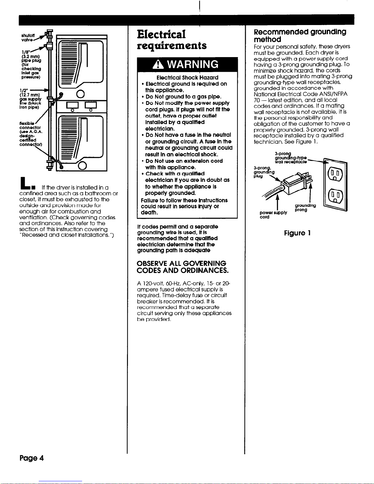
ttexlble
/
connector
(use A.G.A.
dwl n-
1 certl ed
connector)
\
L
W If the dryer is installed in a
confined area such as a bathroom or
closet, it must be exhausted to the
outside and provision made for
enough air for combustion and
ventilation. (Check governing codes
and ordinances. Also refer to the
section of this instruction covering
“Recessed and closet installations.“)
Electrical
reauirements
*
Electrlcal Shock IHazard
l
Electrlcal ground Is required on
thls appliance.
l
Do Not ground to a gas pipe.
l
Do Not modlty the power supply
cord plugs. It plugs will not tit the
outlet, have a proper outlet
Installed by a quallfled
electrlclan.
l
Do Not have a fuse In the neutral
or groundlng clrcult. A tuse In the
neutral or groundlng 8clrcult could
result In an electrlcal shock.
l
Do Not use an extension cord
wlth thls appliance.
l
Check wlth a qualltled
electrlclan It you are In doubt as
to whether the appliance Is
properly grounded.
Failure to tallow these lnstructlons
could result In serious ln)ury or
death.
It codes permit and a separate
groundlng wire Is used, It Is
recommended that a qualltled
electrlclan determlne that the
groundlng path Is adequate
OBSERVE ALL GOVERNING
CODES AND ORDINANCES.
A 120-volt, XI-Hz, AC-only, 15- or 20
ampere fused electrical supply is
required. Time-delay fuse or circuit
breaker is recommended. It is
recommended that a separate
circuit serving only these appliances
be provided.
T
zcordmended grounding
For your personal safety, these dryers
must be grounded. Each dryer is
equipped with a power supply cord
having a 3-prong grounding plug. To
minimize shock hazard, the cords
must be plugged into mating 3-prong
grounding-type wall receptacles,
grounded in accordance with
National Electrical Code ANSVNFPA
70 - latest edition, and all local
codes and ordinances. If a mating
wall receptacle is not available, it is
the personal responsibility and
obligation of the customer to have a
properly grounded, 3-prong wall
receptacle installed by a qualified
technician, See Figure 1.
3-pron
groun ng-type
8
wall receptacle 1
I
groundlng
POT SUPPM
prong
Figure 1
Page 4
 Loading...