

Maytag 336729 Installation Manual
GAS
BUILT-IN
OVEN
INSTALLikilbN
GUIDE
TO THF INSTALLER: Leave this guide with the oven.
NOTE: If
outslde
venting is desired or required by local building codes,
a vent kit is available. Contact your nearest Dealer.
IMPORTANT: Readlhe Rules for Safe Use in your Use and Care
Manual before using your oven.
KEEP
T#IS.
GUIDE
For Future
Reference .
TOOL LIST
The following tools are needed to install your new oven.
1. l/8” drill bit
2. Electric or hand drill
3. Flat bladed screwdriver
4. No. 1 or No. 2 Phillips screwdriver
5. Pencil
6. Ruler and straight edge
7. Hand saw or sabre saw
8. Pipe wrench
9. 5/0” wrench and l/2” wrench or adjustable wrench
10. l/4” hex socket drive
LOr,ATION
cat) III>! !~~,sce, with 5 solId s~dcs,
rnllsl br:
provided lo complclely
enclOSe
the ICC? c<td part of your bul’l-In oven except for the vent lhlmble on the
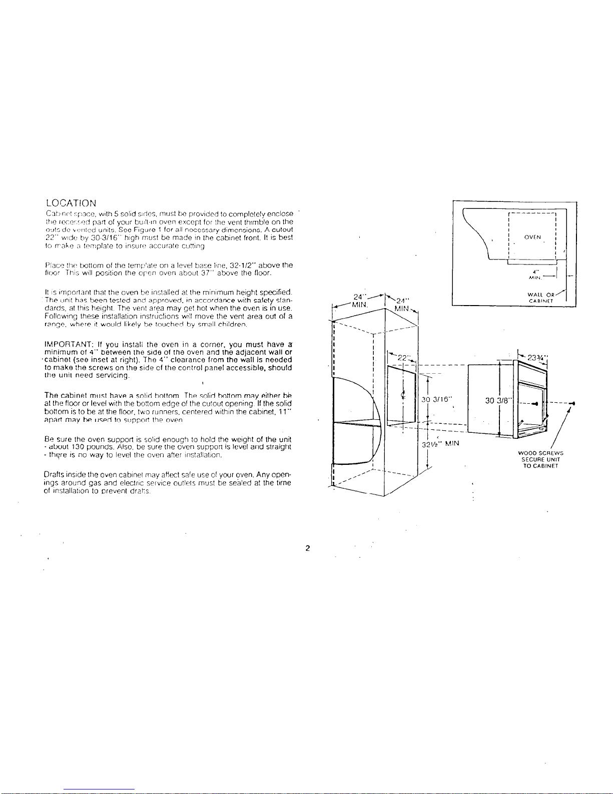
WI: dc \c,nlcd units. See Figure 1 for all necessary dimensions. A culoul
22” wdc by 30-3/l 6” high musl be made I” Ihe cablnel front. It IS bes!
to frske a lcmplale lo rnsurt accurale cuDng
f’!acc lhc tiotlom of Ihe temlj’are on a level base Ilne. 32-l/2” above the
flt,~~o: lhs WIII pOsition the open oven about 37” above Ihe floor.
II IS Imporlant thal the oven be Installed at the minimum height specified.
The unll has been tesled and approved, in accordance wilh safely standards, al this height The venl area may gel hot when Ihe oven is In use.
FolIowIng these insfallallon tnslrucllons wII move the vent area out of a
range, where I! would likely be touched by small children
IMPORTANT: If you install the oven in a corner. you must have a
minimum of 4” belween the side of the oven and the adjacent wall or
,cabinet (see insel a! right). The 4” clearance from the wall Is needed
lo make the screws on the side of the control panel accessible, should
the unit need servicing.
The cabinel must have a solid bottom. The solid bottom may either ti
al the flmr or level with lhe boflom edge of the cutout opening. If Ihe solid
bottom is lo be at Ihe floor. two runners, cen:ered wlthln the cabinet. 11”
apan may be used lo support lhe oven
Be sure the oven support is solid enough lo hold the weigh1 of the unit
about 130 pounds. Also, be sure the oven support is level and straight
- lhgre IS no way to level the oven atter mslallallon.
Drafts insde the oven cabinet may affect sale use 01 your oven. Any openings around gas and electric service outlets must be seAled al the time
of lnslallallon to prevent drars
t-
23%”
--I
I?---+
-7’
i
WOOD SCREWS
SECURE UNIT
TO CABINET
EtECTRICAL CONNECTIONS
Check wlfh your&al ulllllles for elecfrlcal codes which apply in your area
II lhere are no local codes. Ihe Nalional Eleclrical Code, ANSliNFPA No.
70-1987 must be followed. You can get a copy by writing:
National Fire Protection Association
Banerymarch Park
Oulncy, MA 02269
An adequate electrical supply and outlet must tx used la operate the elecfrical pans of your oven. The oven cord has a three prong plug and must
be used with a properly grounded lhree hole oullel wllh a standard 120
volt. 60 cycleOAC household current. Never use an extension cord to connect Ihe oven to the electrical supply
lnslall Ihe electrical outlet below Ihe oven on the right side. It should be
easily reached through cabinet doors below Ihe oven. See Figure 5.
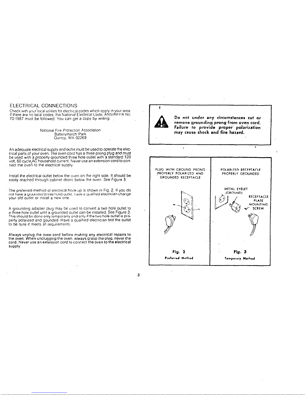
The preferred melhod of electrical hook-up is shown In Fig. 2. If you do
not have a grounded (rhree hole) wllel. have a quaIlfled eleclrician change
your old outlet or lnslall a new one.
A grounding adapter plug may be used to convert a two hole outlet lo
a three hole outlet until a grounded outlet can be installed. See Figure 3.
This should be done only lemporarlly and only II Ihe two hole outlet IS pr@
perly polarized and gounded. Have a quaIlfled electnclan test the outlet
lo be sure II meets all requirements.
Always un lug the oven-cord before making any eleclrical repairs lo
(he oven.
Ji hen unplugging Ihe oven, always grasp the plug, never Ihe
cord. Never use an extension cord to connecl Ihe oven lo Ihe electrical
suPPlY
Do not under any circumstances cut or
remove grounding prong from oven cord.
Failure to provide proper- polarization
may cause shock and fire
hJzJrd.
PLUG WITH GROUND PRONG
,PPOPERLY POLARIZED AND
GROUNDED RECEPTACLE
POLARIZED RECEPTACIE
PROPERLY GROUNDED
METAL EYELET
RECEPTACLE
Fig. 2 Fig. 3
Prdwrd Method
lomporr~ hIhod
3
 Loading...