

Maytag 335344 Installation Manual
FREESTANDING SPARK IGNITION
GAS RANGE INSTALLATION GUIDE
TO THE INSTALLER: Leave this guide with the range.
IMPORTANT:
Read the Rules for Safe Use in your Use and Care
Manual before using your range.
L
TOOL LIST
KEEP THIS
GUIDE
For Future
Reference
The following tools are needed to install your new
range.
1. l%“, lY16” and VZ” open wrenches or an adjustable wrench
2. Pipe wrench
3. YE” and f/g” flat blade screwdrivers
I
I
4. Pliers
(St)
1
WHPL # 4348091
Part No. 335344
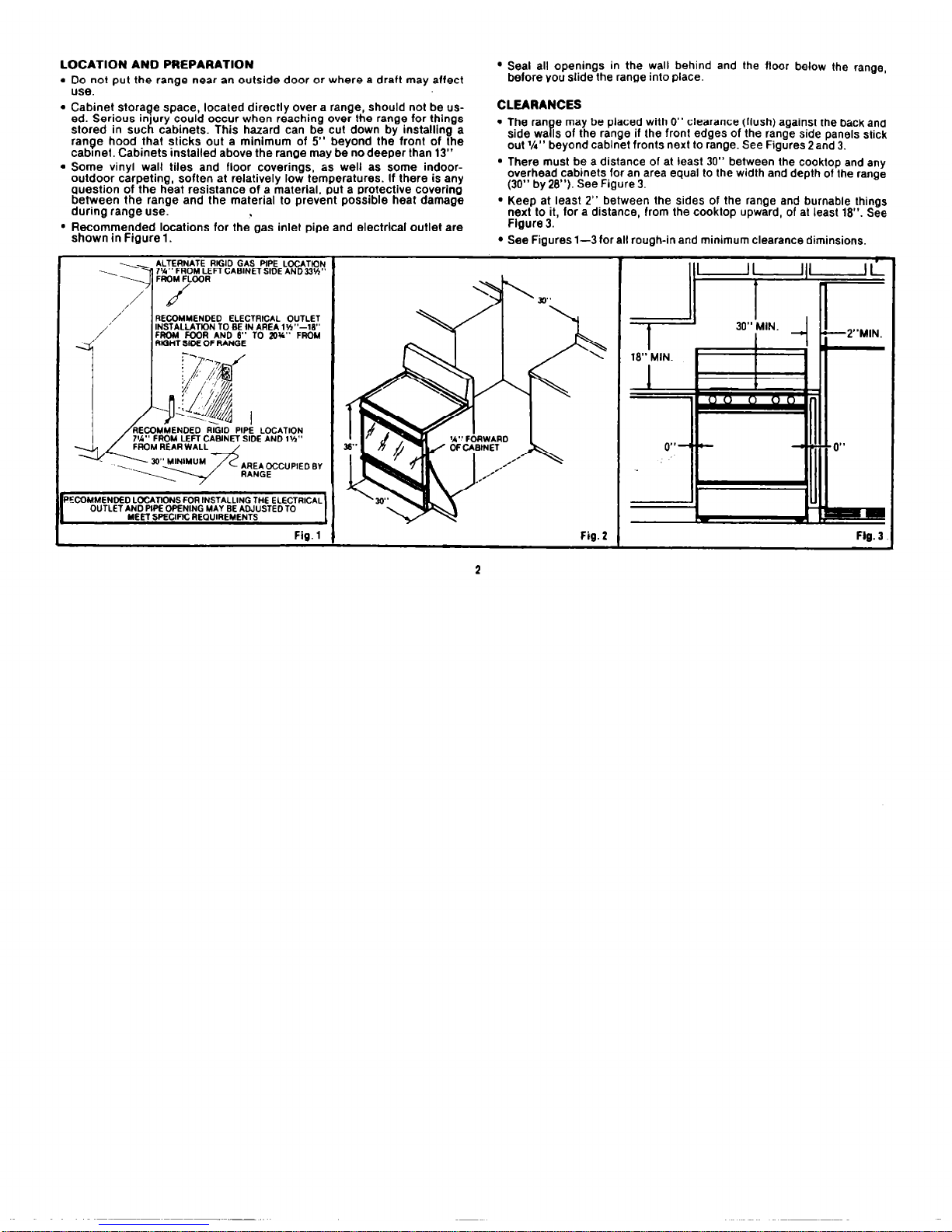
LOCATION AND PREPARATION
l
Do not put the range near an outside door or where a draft may affect
use.
l
Seal all openings in the wall behind and the floor below the range,
before you slide the range into place.
l
Cabinet storaoe soace. located directlv over a range. should not be used. Serious injury’could occur when reaching over the range for thlngs
stored in such cabinets. This hazard can be cut down by installing a
range hood that sticks out a mlnimum of 5” beyond the front of the
cabmet. Cabinets installed above the range may be no deeper than 13”
l
Some vinyl wall tiles and floor coverings, as well as some indooroutdoor carpeting, soften at relatively low temperatures. If there is any
question of the heat resistance of a material, put a protective covering
between the range and the material to prevent possible heat damage
during range use.
CLEARANCES
l
The ran e may be placed with 0” clearance (flush) against the back and
side wa Is of the range if the front edges of the range side panels stick B
out l/t” beyond cabinet fronts next to range. See Figures 2 and 3.
l
There must be a distance of at least 30” between the cooktop and any
overhead cabinets for an area equal to the width and depth of the range
(30” by 28”). See Figure 3.
l
Keep at least 2” between the sides of the range and burnable things
next to it, for a distance, from the cooktop upward, of at least 18”. See
l
Recommended locations for the gas inlet pipe and electrlcal outlet are
shown in Figure 1.
Flgure 3.
l
See Figures l-3 for all rough-in and minimum clearance diminsions.
ALTERNATE RIGID GAS PiPE LCCATlON
RECQMMENDED ELECTRICAL OUTLET
INSTALlATK)N TO BE IN AREA l’h”-18”
FROM FOOR AND 8” TO 20%” FROM
RIGHT SIDE OF RANGE
FROM REAR WALL
‘ECOMMENDED LCCATIONS FOR INSTALLING THE ELECTRICAL
OUTLET AND PIPE OPENING MAY SE ADJUSTED TO
MEET SPECIFIC REQUIREMENTS
Fig.1 1 Fig. 2
Flg. 3
2
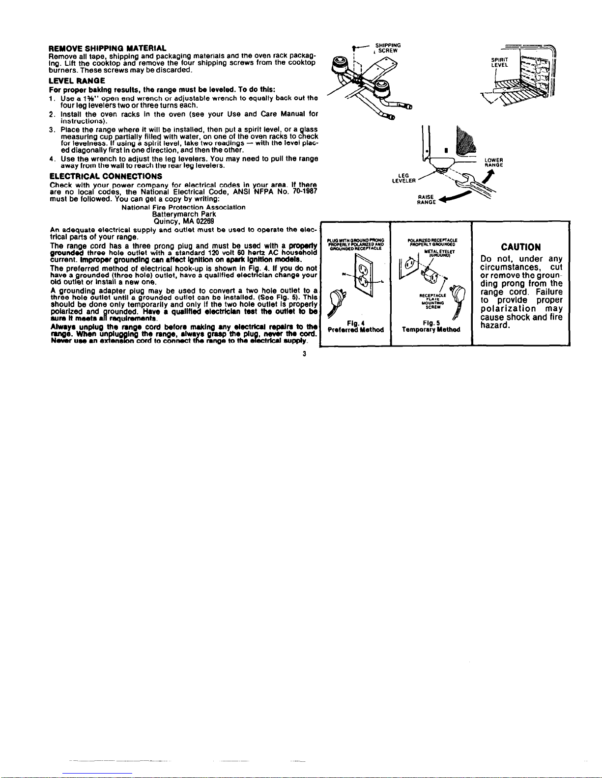
REMOVE SHIPPINQ MATERIAL
Remove all tape, shipplng and packaglng materials and the oven rack packag-
Ing. Lift the cooktop and remove the four shipping screws from the cooktop
burners. These screws may be discarded.
LEVEL RANQE
?--
SHIPPING
, SCREW
For proper baklng results, the range must be leveled. To do this:
1.
Use a 1%” open end wrench or adjustable wrench to equally back out the
four leg levelers two or three turns each.
2. Install the oven racks In the oven (see your Use and Care Manual for
instructions).
3. Place the range where it will be installed, then put a spirit level, or a
lass
measuring cup partially filled with water, on one of the oven racks to c
7l
eck
for levelness. If using a s
lrit
ed diagonally first In one
If
level, take two readlngs - with the level plac-
lrectlon, and then the other.
4. Use the wrench to adjust the leg levelers. You may need to pull the range
away from the wall to reach the rear leg levelers.
ELECTRICAL CONNECTIONS
Check wlth your power corn
any
for electrlcal codes In your area. If there
are no local codes. the
Nat onal Electrlcal Code. ANSI NFPA No. 70-1967 P
LEG
LEVELER
must be followed. Ybu can get a copy by wrltlng:
’
Natlonal Fire Protection Assoclatlon
Batterymarch Park
Ouincy, MA 02269
An adequate electrlcal supply and outlet must be used to operate the electrlcal parts of your range.
The range cord has a three prong plug and must be used wlth a my
grounded three hole outlet with a standard 120 volt 60 hertz AC household
current. Improper grounding un affect lgnltlon on apuk Ignltlon modds.
The preferred method of electrical hook-up is shown In
Fl B 4. If you do not
have a grounded (three hole) outlet, have a quallfled electr clan
change your
old outlet or Install a new one.
A grounding adapter plug may be used to convert a two hole outlet to a
three hole outlet until a grounded outlet can be Installed. (See Flg. 5). Thls
should be done only temporarlly and only If the two hole outlet Is properly
polarized and
9
rounded.
sum It meeta
Have a qualINed elactrkkn teat the outlet to k
requIrementa.
3
CAUTION
Do not, under any
circumstances, cut
or remove the grounding prong from the
range cord. Failure
to provide proper
polarization may
cause shock and fire
hazard.
 Loading...