

Maytag 318064000 Installation Manual

Part No. 318064000 Rev. B/4372426 Rev. A
Before you start.. . ~;~;,g;;$gy;g~&~~~
Grounded electrical
Instsllation must be done by a qualified
outlet is required. See
supply
requirements,” panel B,
“Electrical requirements,”
installer.
Important: Observe all governing
Panel B.
Proper installation is your responsibility.
codes and ordinances.
Recessed installation
Make sure you have everything
Failure to meet codes and
area must provide
necessary for correct installation. It is the
ordinances could lead to fire or
complete enclosure
responsibility of the installer to comply
electrical shock hazard. around the recessed
with the installation clearances specified
ADDITIONAL SAFEGUARDS
portion of oven.
on the seriaurating plate. The
seriavrating plate is located behind the
. Do not install wall oven
oven door on the front frame.
beneath the work counter.
. The flue discharge shall not be
located below the 36 inch level.
WARNING: If the information
in this manual is not followed
exactly, a fire or explosion
may result causing property
damage, personal injury or
death.
- Do not store or use gasoline
or other flammable vapors
and liquids in the vicinity of
this or any other appliance.
- WHAT TO DO IF YOU SM.SLL
GAS
. Do not try to light any
appliance.
. Do not touch any electrical
switch; Do not use any
phone in your building.
. Immediately call your gas
supplier from a neighbor’s
phone. Follow the gas
supplier’s instructions.
. If you cannot reach your
gas supplier, call the fire
department.
- Installation and service
must be performed by a
qualified installer, service
agency or the gas supplier.
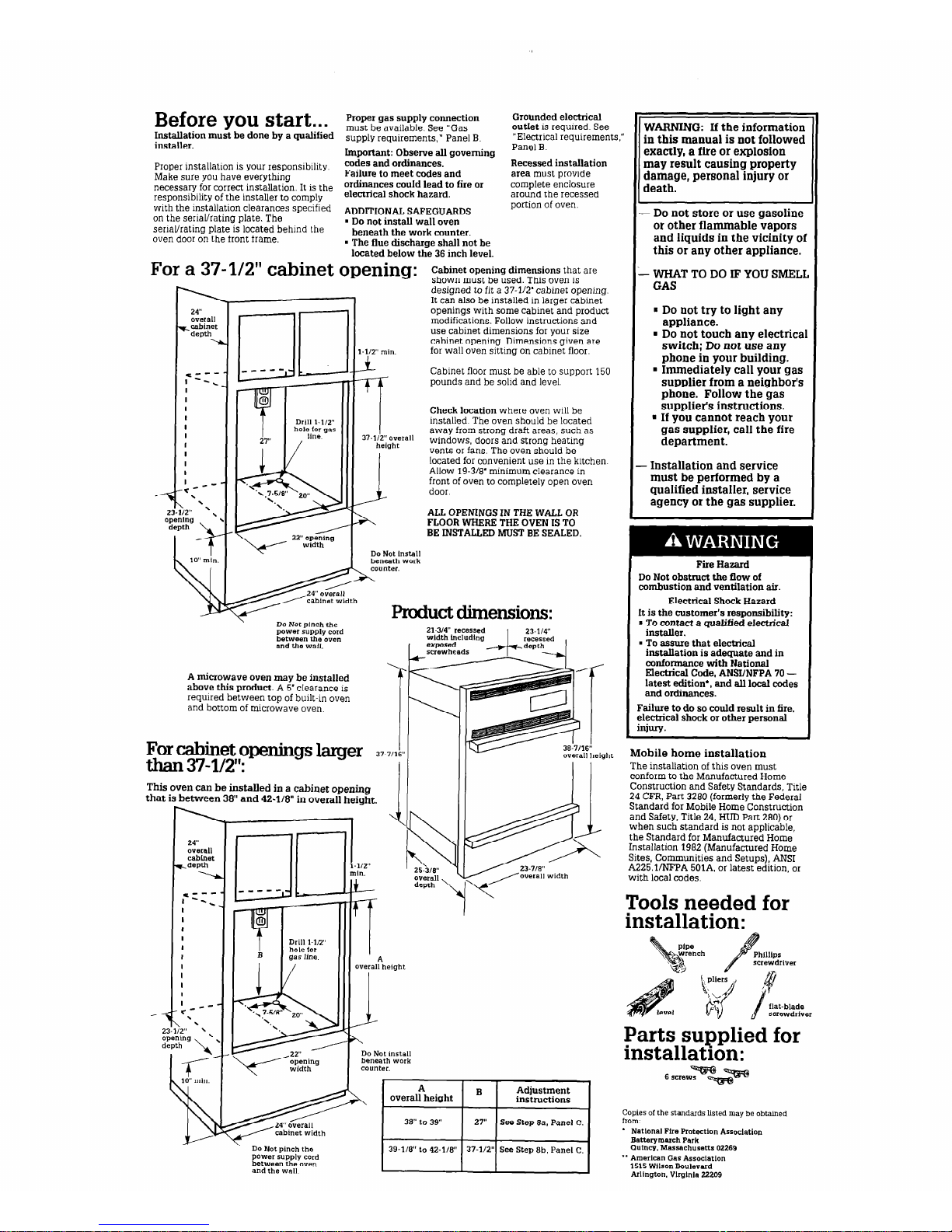
For a 37-l/2” cabinet opening:
1
24”
overall
r_cabinet
depth
\
nr
1.112” min.
Cabinet opening dimensions that are
shown must be used. This oven is
designed to fit a 37-l/2’ cabinet opening.
It can also be installed in larger cabinet
openings with some cabinet and product
modifications. Follow instructions and
use cabinet dimensions for your size
cabinet opening. Dimensions given are
for wall oven sitting on cabinet floor.
,= z
--
-.
I
I
I
I
I
I
I
I
I
I
I
*---
\
\
iz*s '\
Cabinet floor must be able to support 150
pounds and be solid and level.
Check location where oven will be
installed. The oven should be located
away from strong draft areas, such as
windows, doors and strong heating
vents or fans. The oven should be
located
for convenient use in the kitchen.
Allow 19-318’ minimum clearance in
front of oven to completely open oven
3
door
A
ALL OPENINGS IN THE WALL OR
FLOOR WHERE THE OVEN IS TO
BE INSTALLED MUST BE SEALED.
Do Not Install
beneath work
_ counter.
$s&zP
Pmduct dimensions:
\
Do Not pinch the
power supply cord
between the oven
and the wall.
Fire
Hazard
Do Not obstruct the flow of
combustion and ventilation air.
Electrical Shock Hazard
It is the customer’s responsibility:
* To
contact
a guaMfad electrical
installer.
. To assure that electrical
installation is adequate and in
conformance with National
Electrical Code, ANSUNFPA 70 latest edition*, and all local codes
and ordinances.
Failure to do so could result in fire,
electrical shock or other personal
injury.
21-X4"
recessed
width Lncludlng
A microwave oven may be installed
above this product. A 5’ clearance is
required between top of built-in oven
and bottom of microwave oven.
For cabinet openhgs larger
37-711br
than 37-l/2”:
I
Mobile home installation
The installation of this oven must
conform to the Manufactured Home
Construction and Safety Standards, Title
24 CFR, Part 3280 (formerly the Federal
Standard for Mobile Home Construction
and Safety, Title 24, HUD Part 290) or
when such standard is not applicable,
the Standard for Manufactured Home
Installation 1982 (Manufactured Home
Sites, Communities and Setups), ANSI
A225.VNFPA 501A, or latest edition, or
with local codes.
This oven can be installed in a cabinet opening
that is between 38” and 42-l/8” in overall height.
Ir
24"
overall
cabinet
t,depth
---I
I’ c.
--
-.
I
I
I
I
I
I
I
I
I
I
I
c---
.
\ '
overall
depth
Tools needed for
installation:
Parts supplied for
installation:
6 scr.wF~-
A
overall height
B
Adjustment
instructions
Copies of the standards listed may be obrained
hl”:
* Netlonal Fire Protection Association
Batterymarch Park
Qut"cg.Massachuse~s02269
*’ American Gas Association
1515 WilsonBoulevard
Arlington. Vlrghlla 22209
39-118” to 42-118”
\
Do Not pinch the
Power Supply cord
between the oven
and the wall
Gas supply
requirements
Observe all governing codes and
ordinances.
Fire Hazard
. Oven must be connected to a
regulated gas supply.
m L.P. gas supply must Not exceed
a pressure of 14” water column.
This must be checked by a
qualified technician before
installing this oven.
. Do Not use an open flame to test
for leaks from gas connections.
. New A.G.A.-design-certified.
flexible gas line should be used
when local codes permit.
Failure to follow these instructions
could result in a fire, explosion or
personal injury.
A
. This installation must conform
with local codes and ordinances. In the
absence of local codes, installations must
conform with American National
Standard, National Fuel Gas Code ANSI
2233.1 - latest edition**.
B
. Input ratings shown on the
serial/rating plate are for elevations up to
2,000 feet. For elevations above 2,000
feet, ratings are reduced at a rate of 4%
for each 1,000 feet above sea level.
C
n
This oven is equipped for use with
NATURAL and L.P. gases. It is designcertified by A.G A. for NATURAL and
L.P. gases with appropriate conversion
The seriaurating plate, located behind
the oven door on the oven frame, has
information on the type of gas that can
be used. If this information does not
agree with the type of gas available,
check with the local gas supplier. See
Panel E for L.P. gas conversion
instructions.
D
. Provide a gas supply line of 314”
rigid pipe to the oven location, A smaller
size pipe on long runs may result in
insufficient gas supply. Pipe-joint
compounds made for use with L.P. gas
must be used. With L.P. gas, piping or
tubing size can be l/2’ minimum. L.P gas
suppliers usually determine the size and
materials used on their system.
E
n
If local codes permit, A.G.A.design-certified flexible metal tubing is
recommended for connecting this oven to
the gas supply line. Do Not kink or
damage the flexible tubing when moving
the oven. A l/2” male pipe thread is
needed for connection to pressure
regulator female pipe threads.
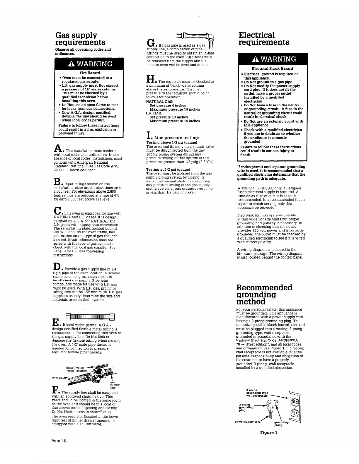
n
line
r
. The supply line shall be equipped
with an approved shutoff valve. This
valve should be located in the same room
as the oven and should be in a location
that allows ease of opening and closing.
Do Not block access to shutoff valve.
The oven regulator (located in the lower,
right rear of broiler drawer opening) is
equipped with a shutoff valve.
G
. If rigid pipe is used as a gas
supply line, a combination of pipe
fittings must be used to obtain an in-line
connection to the oven. All strains must
be removed from the supply and fuel
lines so oven will be level and in line.
H
n
The reoulator must be checked at
a minimum ofj-inch water column
above the set pressure. The inlet
pressure to the regulator should be as
follows for operation:
NATURAL GAS:
Set pressure 4 inches
Maximum pressure 14 inches
L.P. GAS:
Set pressure 10 inches
Maximum pressure 14 inches
I
. Line pressure testing:
Testing above l/2 psi (gauge)
The oven and its individual shutoff valve
must be disconnected from the gas
supply piping system during any
pressure testing of that system at test
pressures greater than l/2 psig (3.5 kPa).
Testing at 112 psi (gauge)
The oven must be isolated from the gas
supply piping system by closing its
individual manual shutoff valve during
any pressure testing of the gas supply
piping system at test pressures equal to
or less than l/2 psig (3.5 kPa).
Electrical
requirements
Electrical Shock Hazard
. Electrical ground is required on
this appliance.
l
Do Not ground to a gas pipe.
- Do Not modify the power supply
cord plug. If it does not fit the
outlet. have a proper outlet
installed by a qualified
electrician.
m Do Not have a fuse in the neutral
or grounding circuit. A fuse in the
neutral or grounding circuit could
result in electrical shock.
n
Do Not use an extension cord with
this appliance.
m Check with a qualified electrician
if you are in doubt as to whether
the appliance is properly
grounded.
Failure to follow these instructions
could result in serious injury or
death.
If codes permit and separate grounding
wire is used, it is recommended that a
qualified electrician determine that the
grounding path is adequate.
A 120~volt, 60-Hz. AC-only, 15-ampere.
fused electrical supply is required. A
time-delay fuse or circuit breaker is
recommended. It is recommended that a
separate circuit serving only this
appliance be provided.
Electronic ignition systems operate
within wide voltage limits but proper
grounding and polarity is necessary. In
addition to checking that the outlet
provides 120~volt power and is correctly
grounded, the outlet must be checked by
a qualified electrician to see if it is wired
with correct polarity.
A wiring diagram is included in the
literature package. The wiring diagram
is also located behind the control panel.
Recommended
grounding
method
For your personal safety, this appliance
must be grounded. This appliance is
manufactured with a power supply cord
having a 3-prong grounding plug. To
minimize possible shock hazard, the cord
must be plugged into a mating, 3-prong,
grounding-type, wall receptacle,
grounded in accordance with the
National Electrical Code, ANSYNFPA
70 - latest edition*, and all local codes
and ordinances. See Figure 1. If a mating
wall receptacle is not available, it is the
personal responsibility and obligation of
the customer to have a properly
grounded, 3-prong, wall receptacle
installed by a qualified electrician.
3-Prong
grounding-type
wall receptxle
3.prong
grounding
Plug
power supply cord
prong
Figure 1
Panel B
 Loading...