

Maytag 30 BUILT-INMICROWAVE OVEN COMBINATION Installation Manual
30” BUILT-IN
MICROWAVE OVEN
COMBINATION
IMPORTANT
INSTALLER: LEAVE THESE INSTRUCTIONS WITH THE HOMEOWNER.
HOMEOWNER: RETAIN THESE INSTRUCTIONS FOR FUTURE REFERENCE.
ave
Ovens,
Compactors, Room Air Conditioners, Dehumidifiers,
Automatic
Washers, Clothes Dryers, Freezers, Refrigerator-freezers, Ice Makers,Dishwasl
II
Before you begin
Read these instructions completely and carefully.
If followed, they will simplify the installation job.
IMPORTANT:
Observe all governing codes and ordinances.
Failure to follow these instructions could lead
to fire or electrical shock hazard.
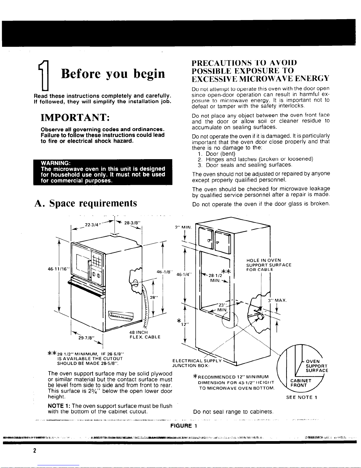
A. Space requirements
46-1
I/
2” MIN.
I
PRECAUTIONS TO AVOID
POSSIBLE EXPOSURE TO
EXCESSIVE MICROWAVE ENERGY
Do not attempt to operate this oven with the door open
since open-door operation can result in harmful ex-
posure to microwave energy. It is important not to
defeat or tamper with the safety interlocks.
Do not place any object between the oven front face
and the door or allow soil or cleaner residue to
accumulate on sealing surfaces.
Do not operate the oven if it is damaged. It is particularly
important that the oven door close properly and that
there is no damage to the:
1. Door (bent)
2. Hinges and latches (broken or loosened)
3. Door seals and sealing surfaces.
The oven should not be adjusted or repaired by anyone
except properly qualified personnel.
The oven should be checked for microwave leakage
by qualified service personnel after a repair is made.
Do not operate the oven if the door glass is broken.
;99-718” 1
FLEX. CABLE
HOLE IN OVEN
SUPPORT SURFACE
FOR CABLE
**28-l/2” MINIMUM, IF 20.518”
IS AVAILABLE THE CUTOUT
SHOULD BE MADE 285/8”.
ELECTRICAL SUPPLY
JUNCTION BOX:
The oven support surface may be solid plywood
or similar material but the contact surface must
be level from side to side and from front to rear.
This surface is 23/4” below the open lower door
height.
NOTE 1: The oven support surface must be flush
with the bottom of the cabinet cutout.
*RECOMMENDED 12”
MINIMUM
DIMENSION FOR 43-l/2” HEIGHT
TO MICROWAVE OVEN BOTTOM.
SEE NOTE 1
Do not seal range to cabinets.
2
B. Check microwave for
damage
Remove all packing material from the oven cavity.
When unpacking the unit, check for damage such as
misaligned door, damaged gaskets around the door,
or dents inside the oven or on the exterior. If there is
any damage, please do not operate the unit until it has
been checked by an authorized Whirlpool trained service technician.
C. Electrical requirements
IMPORTANT:
SAVE THESE INSTRUCTIONS FOR THE
LOCAL ELECTRICAL INSPECTOR’S USE
A. This appliance must be connected to the proper
electrical voltage and frequency as specified on
nameplate. Models rated at 15 KW on 240 volts (11.25
KW on 208V) or more require a separate 50 amp circuit. Models rated less than 15KW on 240 volts (11.25
KW on 208V) require a separate 40 ampere circuit.
Fuse both sides of the line. DO NOT fuse the neutral.
A time delay fuse or circuit breaker is recommended.
Wire sizes must conform to the requirements of the National Electrical Code and/or local codes and ordinances for the kilowatt rating of the range. The
nameplate is located on the front frame behind the
microwave oven door.
NOTE: Wire sizes and connections must conform with
the fuse size and rating of the appliance in accordance
with National Electrical Code and local codes and ordinances. Do not use an extension cord.
B. The appliance should be connected to the fused
disconnect (or circuit breaker) box through flexible armored or non-metallic sheathed cable. The flexible armored cable extending from the appliance should be
connected directly to the junction box. The junction box
should be locat.ed as shown in Figure 1 on page 2 so
that as much slack as possible remains in the cable
between the box and the appliance so that it can be
moved if servicing is necessary.
C. A suitable strain relief must be provided to attach
the flexible armored cable to the junction box.
 Loading...