

Page 1

W10251148
SERVICE MANUAL
Maytag
Model 30 Commercial
Front Loading Washers
MODELS:
MHN30PDAWW0
MHN30PDAXW0
MHP30PRAWW0
MHN30PRAWW0
TECHNICAL EDUCATION
Page 2

FORWARD
This Maytag Service Manual, (Part No. W10251148), provides the Commercial
Laundry Service Professional with information on the installation, operation, and
service of the single load coin and non coin Model 30 Series Commercial Front
Loading Washers. For specic information on the model being serviced, refer to
the “Installation Instructions,” or “Tech Sheet” provided with the washer. The Wiring
Diagrams used in this Service Manual are typical and should be used for training
purposes only. Always use the Wiring Diagram supplied with the product when
servicing the washer.
GOALS AND OBJECTIVES
The goal of this Service Manual is to provide information that will enable the
Commercial Laundry Service Professional to properly diagnose malfunctions and
repair the Commercial Front Loading Washers. The objectives of this Service
Manual are to:
Understand and follow proper safety messages.
•
Understand and diagnose improper installations.
•
Successfully troubleshoot and diagnose malfunctions.
•
Successfully perform necessary repairs.
•
Successfully return the washer to its proper operational status.
•
WHIRLPOOL CORPORATION assumes no responsibility
for any repairs made on our products by anyone other than
authorized Commercial Laundry Service Professionals.
Copyright © 2011, Whirlpool Corporation, Benton Harbor, MI 49022
ii
Page 3

TABLE OF CONTENTS
View entire service video ..................................................................................................vi
Links to documents ........................................................................................................... vi
Installation Instructions................................................................................................ vi
Tech Sheet - (English) .................................................................................................vi
Tech Sheet - (French) ................................................................................................. vi
Page
GENERAL .................................................................................................................................
Model number designations .............................................................................................. 1-2
Serial number designations .............................................................................................. 1-2
Model & serial number label and tech sheet location ....................................................... 1-3
Specications .................................................................................................................... 1-4
Warranty ........................................................................................................................... 1-5
INSTALLATION REQUIREMENTS ...........................................................................................
Tools and parts .................................................................................................................2-1
Alternate parts ..................................................................................................................2-2
Accessories ......................................................................................................................2-2
Options .............................................................................................................................2-2
Location requirements ...................................................................................................... 2-3
Drain system ..................................................................................................................... 2-4
Electrical requirements ..................................................................................................... 2-5
Remove shipping bolts .....................................................................................................2-6
Reinstall shipping bolts .....................................................................................................2-6
BASIC OPERATION .................................................................................................................
Set up instructions ............................................................................................................ 3-1
General user information .................................................................................................. 3-2
Control set-up procedures ................................................................................................ 3-4
Remove AA1 jumper ......................................................................................................... 3-5
Set-up codes ..................................................................................................................... 3-6
1-1
2-1
3-1
COMPONENT ACCESS ...........................................................................................................
Component locations ........................................................................................................4-1
Chemical dispenser drawer and parts .............................................................................. 4-2
Remove facia and control panel cover .............................................................................4-2
Lift washer top ..................................................................................................................4-3
Remove control panel ....................................................................................................... 4-4
Remove user interface control (UIC) ................................................................................ 4-5
Remove key pad assembly ............................................................................................... 4-6
Remove control panel bracket .......................................................................................... 4-7
Remove central control unit (CCU) ................................................................................... 4-8
CCU connections .............................................................................................................. 4-9
Remove water inlet valves ................................................................................................ 4-10
Remove pressure switch ..................................................................................................4-11
Remove RFI line lter ....................................................................................................... 4-12
Remove power supply cord .............................................................................................. 4-13
Remove chemical dispenser assembly ............................................................................4-14
4-1
iii
Page 4

TABLE OF CONTENTS - CONTINUED
Page
Remove transformer .........................................................................................................4-15
Remove door lock / switch assembly ................................................................................ 4-16
Remove door hook ...........................................................................................................4-18
Remove door and hinge assembly ................................................................................... 4-18
Door parts and disassembly ............................................................................................. 4-19
Remove lower service panel ............................................................................................. 4-21
Remove drain pump .........................................................................................................4-22
Remove drain pump motor ............................................................................................... 4-24
Remove tub to pump hose ................................................................................................ 4-25
Remove ground switch ..................................................................................................... 4-26
Remove rear panel ........................................................................................................... 4-28
Remove motor control unit (MCU) ....................................................................................4-29
Remove temperature sensor ............................................................................................ 4-30
Remove drive belt ............................................................................................................. 4-31
Remove motor .................................................................................................................. 4-32
Remove basket pulley ......................................................................................................4-33
Remove air gap damper ................................................................................................... 4-34
Remove vent tube ............................................................................................................. 4-35
Remove water inlet valve - from the back ......................................................................... 4-35
Remove front panel ..........................................................................................................4-36
Remove the bellow ........................................................................................................... 4-37
Remove a pedestal ........................................................................................................... 4-38
Remove tub and spin basket assembly ............................................................................ 4-39
Replace bafe ................................................................................................................... 4-42
Remove metercase (model MHN30PD) ........................................................................... 4-43
Remove coin drop (model MHN30PD) ............................................................................. 4-44
Remove coin vault switch (model MHN30PD) .................................................................. 4-45
Remove service switch (model MHN30PD) ...................................................................... 4-46
Main top support ...............................................................................................................4-46
COMPONENT TESTING ...........................................................................................................
Inlet valve solenoids .........................................................................................................5-1
Pressure switch ................................................................................................................5-2
RFI line lter ...................................................................................................................... 5-3
Door lock assembly ..........................................................................................................5-4
Drain pump motor .............................................................................................................5-5
Temperature sensor .......................................................................................................... 5-6
Drive motor ....................................................................................................................... 5-7
Ground switch ................................................................................................................... 5-7
User interface membrane switch ...................................................................................... 5-8
Coin drop acceptor ...........................................................................................................5-9
Transformer ...................................................................................................................... 5-10
5-1
iv
Page 5

TABLE OF CONTENTS - CONTINUED
Page
DIAGNOSIS & TROUBLESHOOTING ..................................................................................... 6-1
Washer diagnostic mode .................................................................................................. 6-1
Failure / error display codes .............................................................................................6-2
Diagnostic test .................................................................................................................. 6-6
Code display .....................................................................................................................6-6
Flashing mode .................................................................................................................. 6-7
Special cycle mode ........................................................................................................... 6-7
Quick overview test ........................................................................................................... 6-8
Manual overview test ........................................................................................................6-9
Diagnostic test quick guide ............................................................................................... 6-10
Help mode ........................................................................................................................6-10
Button functions in help mode table .................................................................................. 6-11
Help mode symbols and elements .................................................................................... 6-11
Help codes ........................................................................................................................ 6-12
Help mode submenu ......................................................................................................... 6-12
Pump motor continuity test ............................................................................................... 6-13
Drive motor ohm test ........................................................................................................6-13
Transformer ohm test ........................................................................................................6-13
Water temperature sensor ................................................................................................6-13
Cycle temperature selections ...........................................................................................6-13
CCU wire harness connector table ...................................................................................6-14
Manually unlocking the door latch ....................................................................................6-15
Manually unlatching tripped door latch ............................................................................. 6-15
Washer care ......................................................................................................................6-15
Washer clean-out cycle procedure ................................................................................... 6-16
Troubleshooting guide ...................................................................................................... 6-17
WIRING DIAGRAM ...................................................................................................................
7-1
v
Page 6
INTERACTIVE SERVICE MANUAL INSTRUCTIONS
Click the mouse on any topic in the table of contents to go directly to that section.
Click the mouse on any link that says (See page ?-?) to go directly to the page referenced.
Click the mouse on any button in the links section to open the attached document.
This symbol means a video clip is available. Click the mouse on the camera icon
to view the video. To close the movie, click the X box at the top corner of the video window.
System requirements to view the video clips in this manual are:
Windows 2000 or higher, Adobe® Acrobat® Reader® version 6 or higher,
Windows Media Player for PC and Quicktime Player for Macintosh computers.
LINKS TO DOCUMENTS
vi
Page 7
GENERAL
WASHER SAFETY
IMPORTANT
Electrostatic Discharge (ESD)
Sensitive Electronics
ESD problems are present everywhere. ESD may damage or weaken
the electronic control assembly. The new control assembly may appear
to work well after repair is nished, but failure may occur at a later date
due to ESD stress.
• Use an anti-static wrist strap. Connect wrist strap to green ground
connection point or unpainted metal in the appliance
-OR-
Touch your nger repeatedly to a green ground connection point or
unpainted metal in the appliance.
• Before removing the part from its package, touch the anti-static bag
to a green ground connection point or unpainted metal in the
appliance.
• Avoid touching electronic parts or terminal contacts; handle
electronic control assembly by edges only.
• When repackaging failed electronic control assembly in anti-static
bag, observe above instructions.
1-1
Page 8

n
Horizontal
Axis Washer Non-Pedestal
Horizontal Axis Washer w/Pedestal
MODeL nUMBer M Hn 30 PD A W W 0
BrAnD
M Maytag
DrIVe TYPe
HN
PrODUCT
30 Commercial HE Front Load W
asher
COnTrOL TYPe
PD
Processor Coindrop
PR Processor Reader
PN Processor Non-coin
CS Mechanical Coinslide
MN Mechanical Non-coin
M
ArKeTInG CODe
A
First series
B Second series
VOLTAGe CODe
W 120V
-60Hz (US)
X
120V
-60Hz (Canada)
G
220-240V
-50Hz (Export Models)
COLO
r
W White
enGIneerInG CHAnGe (nUMerIC)
-
SerIAL nUMBer HL
0 35 10901
D
IVISIOn reSPOnSIBILITY
M
Marion, Ohio
HL Monterrey
, MX
Y
eAr OF PrODUCTIO
W
2008
Y
2009
0
2010
1
201
1
W
eeK OF PrODUCTIOn
35 35th W
eek in the calendar year
M
AnUFACTUrInG SeQUenCe nUMBer
HP
AH
Automatic Horizontal Axis Washer
22
Commercial HE Front Load Washer
2 2012
2013
2014
3
4
2015
5
C Clyde, Ohio
MODEL NUMBER DESIGNATIONS
SERIAL NUMBER DESIGNATIONS
1-2
Page 9
MODEL & SERIAL NUMBER LABEL AND
TECH SHEET LOCATION
Location of
Model & Serial Number Label
Location of
Tech Sheet
Parts List
Wiring Diagram
1-3
Page 10
SPECIFICATIONS
Door
MHN-
MHP -
44.65
Total Hot Water use/cycle*
Total water use/cycle*
(Owner
Adjustable)
Pedestal Equipped
& K nits, Q uick
Whites, Colors, Brights, Perm Press, Delicates
6 Cycles
245 lbs
254 lbs
MHP - 234 lbs /
MHN-230 lbs
Product Weight (uncrated)
Card Reader Not Included
Product Weight (crated)
2 mm)
(7
30.
(68.58 cm)
15 Amps
3.2 ft
Normal = 40 RPM
MHP only
SPeCiFiCaTiOnS
Width
Capacity
Front Load HE Washer
Model Number
MHN30PDAWW
MHN30PRAWW
MHP30PRAWW
Model Description
Color
White / Black Accents
Stainless Steel Trim
Temperature Control
NTC - Thermister
No
Sensors
Suds Sensor
NTC (Thermistor)
Water Level Sensor
W
ash Speed
Spin Speeds
Max = 1000 RPM
Medium = 850 RPM
Low = 750 RPM
Extra Low = 600 RPM
Rated Load Size
18 lbs
V
oltage
120 volts
Frequency
60 Hz
Max
Amp Draw
12
Amps
US Breaker Rating
Amps
Power Cord Length
6 ft
MEF
2.5
W
ater Factor
3.7
11.955 gallons/cycle*
Controlled Induction Motor
Motor Protection
HP
Variable Speed, Reversing
Thermally Protected
1/4 HP
Height
”
Install Depth: Min - Max
28.75”
Money Acceptor
US = Single Coin Drop
Canada = Dual Coin Drop
27"
MHN30PDAY
W
3
MHP - 234 lbs /
MHN-230 lbs
44.65
” /
44.65
”
180° Opening / Non-Reversible
verage loads based on testing using* A
CSA Standard C360-03/DO E Appendix J1/
T396
Hot wash 3.53 gal (13.36 liters) /
Warm wash 1.38 gal (5.22 liters)
1-4
Page 11

WARRANTY
MAYTAG® COMMERCIAL SINGLE-LOAD AND VENDED
MULTI-LOAD WASHER & DRYER
WARRANTY
LIMITED WARRANTY ON PARTS
For the rst ve years from the date of purchase, when this commercial appliance is installed, maintained and operated according to the
instructions attached to or furnished with the product, Maytag brand of Whirlpool Corporation (thereafter “Maytag”) will pay for factory
specied parts or original equipment manufacturer parts to correct defects in materials or workmanship. Proof of original purchase date
is required to obtain service under this warranty.
ITEMS MAYTAG WILL NOT PAY FOR
1. All other costs including labor, transportation, or custom duties.
2. Service calls to correct the installation of your commercial appliance, to instruct you how to use your commercial appliance, to
replace or repair fuses, or to correct external wiring or plumbing.
3. Repairs when your commercial appliance is used for other than normal, commercial use.
4. Damage resulting from improper handling of product during delivery, theft, accident, alteration, misuse, abuse, re, ood, acts of
God, improper installation, installation not in accordance with local electrical or plumbing codes, or use of products not approved
by Maytag.
5. Pickup and Delivery. This commercial appliance is designed to be repaired on location.
6. Repairs to parts or systems resulting from unauthorized modications made to the commercial appliance.
7. The removal and reinstallation of your commercial appliance if it is installed in an inaccessible location or is not installed in
accordance with published installation instructions.
8. Chemical damage is excluded from all warranty coverage.
9. Changes to the building, room, or location needed in order to make the commercial appliance operate correctly.
DISCLAIMER OF IMPLIED WARRANTIES; LIMITATIONS OF REMEDIES
CUSTOMER'S SOLE AND EXCLUSIVE REMEDY UNDER THIS LIMITED WARRANTY SHALL BE PRODUCT REPAIR AS PROVIDED
HEREIN. IMPLIED WARRANTIES, INCLUDING WARRANTIES OF MERCHANTABILITY OR FITNESS FOR A PARTICULAR PURPOSE,
ARE LIMITED TO ONE YEAR OR THE SHORTEST PERIOD ALLOWED BY LAW. WHIRLPOOL SHALL NOT BE LIABLE FOR
INCIDENTAL OR CONSEQUENTIAL DAMAGES. SOME STATES AND PROVINCES DO NOT ALLOW THE EXCLUSION OR LIMITATION
OF INCIDENTAL OR CONSEQUENTIAL DAMAGES, OR LIMITATIONS ON THE DURATION OF IMPLIED WARRANTIES OF
MERCHANTABILITY OR FITNESS, SO THESE EXCLUSIONS OR LIMITATIONS MAY NOT APPLY TO YOU. THIS WARRANTY GIVES
YOU SPECIFIC LEGAL RIGHTS AND YOU MAY ALSO HAVE OTHER RIGHTS, WHICH VARY FROM STATE TO STATE OR PROVINCE
TO PROVINCE.
If you need service, please contact your authorized Maytag® Commercial Laundry distributor. To locate your authorized Maytag®
Commercial Laundry distributor, or for web inquiries, visit www.MaytagCommercialLaundry.com.
3/10
For written correspondence:
Maytag
®
Commercial Laundry Service Department
2000 M-63 North
Benton Harbor, Michigan 49022 USA
10. Repairs made by a non-Whirlpool authorized service technician.
1-5
Page 12

---- NOTES ----
1-6
Page 13
INSTALLATION REQUIREMENTS
For complete installation instructions
See Links to documents page.
Tools and parts
Gather the required tools and parts before
starting installation. The parts supplied are in
the washer spin basket.
Tools needed for connecting the water inlet
hoses:
Pliers (that open to 1 9/16th” {39.5 mm})
•
Flashlight (optional)
•
Tools needed for installation:
1/2” inch wrench
•
9/16” open end wrench
•
T-20 security screwdriver
•
1/4” nut driver
•
Level
•
Wood block
•
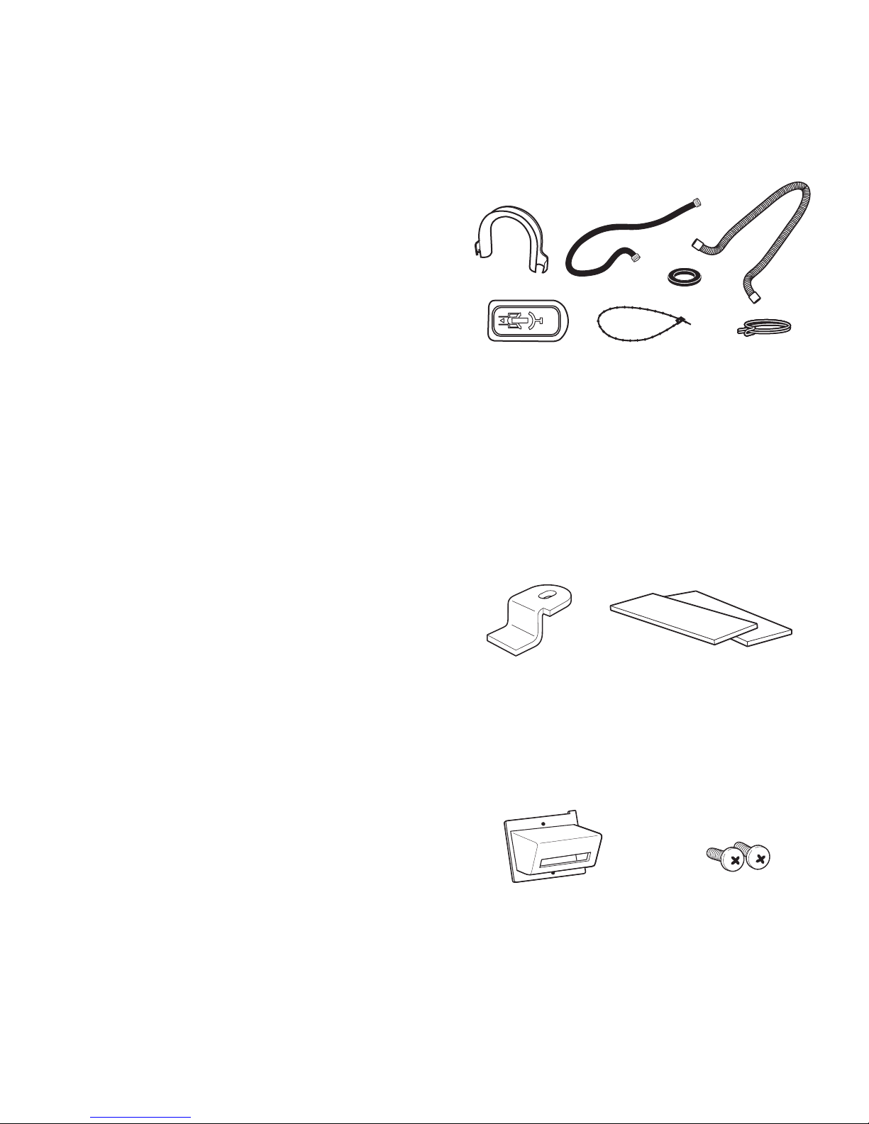
Parts supplied:
A B
C
D E G
A. U-shaped hose form
B. Water inlet hoses (2)
C. Inlet hose washers (4)
D. Transit bolt hole plug (4)
E. Beaded tie strap
F. Drain hose
G. Hose clamp
Parts supplied for PD Models:
F
Ruler or measuring tape
•
Service Door Foam Pads
Lock Cam
Parts supplied for PR Models:
Card Reader Screws
Bezel (2)
2-1
Page 14
ALTERNATE PARTS OPTIONS
Your installation may require additional parts.
If you are interested in purchasing one of the
items listed here, call the toll-free number in
the “Assistance or Service” section.
If You Have You Will Need to Buy
Laundry tub or
standpipe taller
than 96” (2.4 m)
Overhead sewer Standard 20 gal. (76 L),
Floor drain Siphon break, Part
Drain hose too
short
Water faucet
beyond reach of
ll hoses
Sump pump system (if not
already available)
30” (762 mm) tall drain tub
or utility sink and sump
pump (available from local
plumbing suppliers)
Number 285834;
additional drain hose,
Part Number 8318155;
and connector kit, Part
Number 285835
4 ft. (1.2 m) drain hose
extension kit, Part Number
285863
2 longer water ll hoses:
6 ft (1.8 m) Part Number
76314, 10 ft (3.0 m) Part
Number 350008
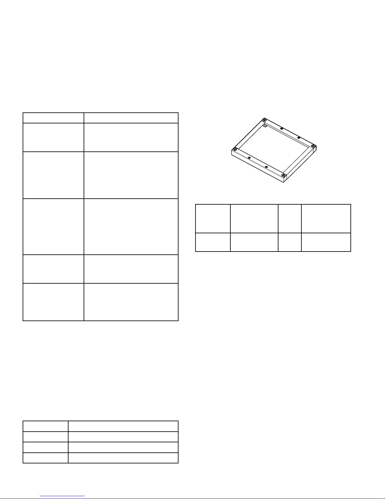
Pedestal
An optional pedestal is available for the other
versions of this model washer. The pedestal
will add to the total height of the washer.
Optional Pedestal
Pedestal
Height
2 7/8”
(73 mm)
NOTE: Model MHP30 has pedestal
pre-installed.
Approximate
Height with
Washer
47.5”
(1207 mm)
Color Model
number
White WHP0400VW
ACCESSORIES
Enhance your washer with these premium
accessories. For more high-quality items or to
order, call 1-800-901-2042,
or visit us at www.maytag.com/accessories.
In Canada call: 1-800-807-6777
or visit us at www.whirlpoolparts.ca.
Part # Accessory
8212526 Washer drip tray, ts under all
31682 All purpose appliance cleaner
1903WH Laundry supply storage cart
2-2
Page 15
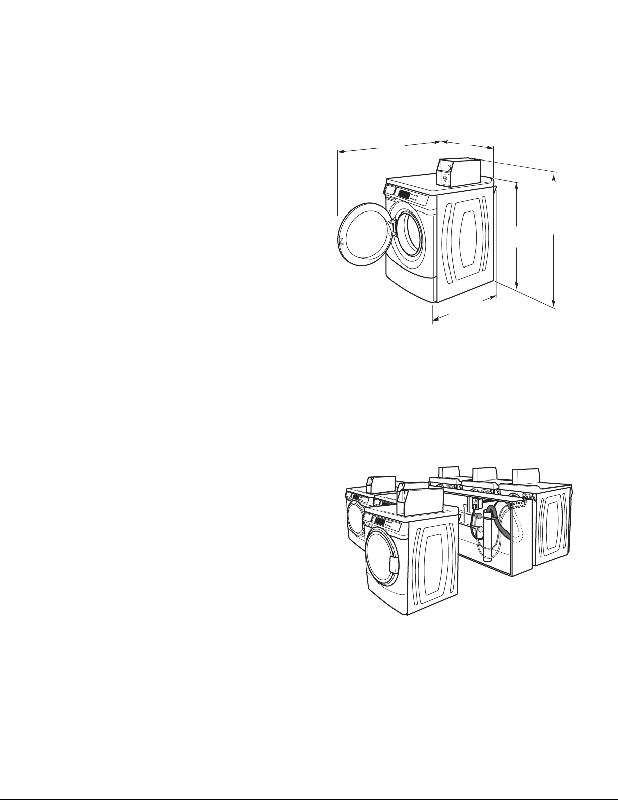
LOCATION REQUIREMENTS
Selecting the proper location for your washer
improves performance and minimizes noise
and possible washer “walk.” Your washer can
be installed under a custom counter, or in a
basement, laundry room, or recessed area.
Companion appliance location requirements
should also be considered. Proper installation
is your responsibility. You will need
A water heater set to deliver 120°F (49°C)
•
water to the washer.
A grounded electrical outlet located within
•
6 ft (1.8 m) of where the power cord is
attached to the back of the washer.
(See page 2-5).
Hot and cold water faucets located within
•
4 ft (1.2 m) of the hot and cold water fill
valves, and water pressure of 20-100 psi
(137.9-689.6 kPa).
A level floor with a maximum slope of 1”
•
(25 mm) under entire washer. Installing
the washer on soft floor surfaces, such as
carpets or surfaces with foam backing, is
not recommended.
A sturdy and solid floor to support the
•
washer with a total weight (water and load)
of 400 lbs (180 kg).
Do not operate your washer in temperatures
below 32°F (0°C). Some water can remain
in the washer and can cause damage in low
temperatures.
Installation clearances
The location must be large enough to allow
•
the washer door to be fully opened.
Additional spacing should be considered for
•
ease of installation and servicing. The door
opens more than 90° and it is not reversible.
Additional clearances might be required for
•
wall, door, and floor moldings.
Additional spacing of 1” (25 mm) on all
•
sides of the washer is recommended to
reduce noise transfer.
Companion appliance spacing should also
•
be considered.
Washer dimensions:
501/2"
(1282 mm)
27"
(686 mm)
13
28
/16"
(732 mm)
3713/16"
(961 mm)
445/8"
(1134 mm)
Door opens 180° and is not reversible.
A oor drain should be provided under the
bulkhead. Prefabricated bulkheads with
electrical outlets, water inlet lines, and drain
facilities should be used only where local
codes permit.
2-3
Page 16
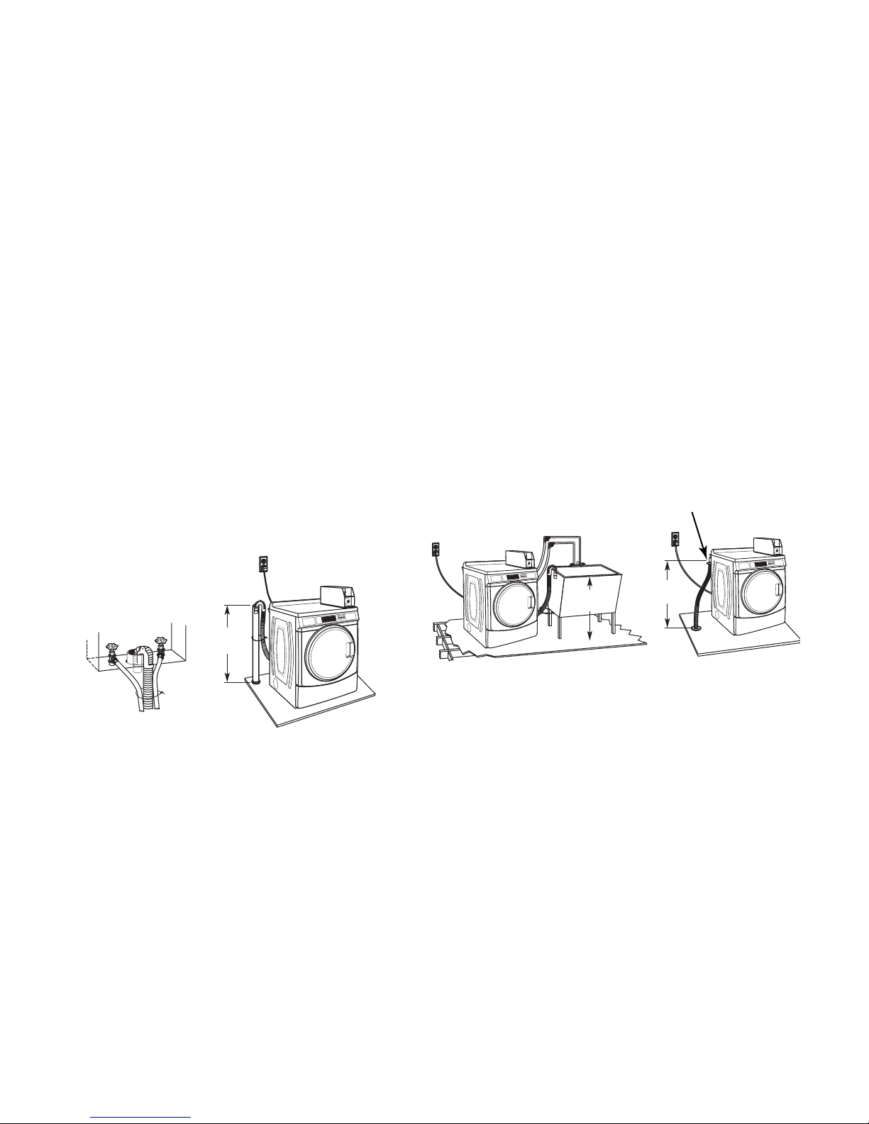
DRAIN SYSTEM
The washer can be installed using the
standpipe drain system (oor or wall), the
laundry tub drain system, or the oor drain
system. Select the drain hose installation
method needed.
Standpipe drain system: wall or oor
(Views A & B)
The standpipe drain requires a minimum
diameter standpipe of 2” (50 mm). The
minimum carry-away capacity can be no less
than 10 gal. (38 L) per minute.
The top of the standpipe must be at least 30”
(762 mm) high and no higher than 96” (2.4 m)
from the bottom of the washer. A drain hose
extension must be added to reach maximum
drain height capability.
Laundry tub drain system (view C)
Laundry tub needs a minimum 20 gal. (76 L)
capacity. The top of the laundry tub must be
at least 30” (762 mm) above the oor.
Floor drain system (view D)
The oor drain system requires a siphon break
that may be purchased separately.
The siphon break must be a minimum of 28”
(710 mm) from the bottom of the washer.
Additional hoses might be needed.
Siphon Break
(Anti-Siphon Device)
30" min.
(762 mm)
A B
30" min.
(762 mm)
28" min.
(710 mm)
C D
2-4
Page 17
ELECTRICAL REQUIREMENTS
Electrical Shock Hazard
Plug into a grounded 3 prong outlet.
Do not remove ground prong.
Do not use an adapter.
Do not use an extension cord.
Failure to follow these instructions can
result in death, fire, or electrical shock.
A 120 volt, 60 Hz., AC only, 15 or 20
•
amp, fused electrical supply is required.
A time-delay fuse or circuit breaker is
recommended. It is recommended that a
separate circuit serving only this appliance
be provided.
Export models require a 220 / 240 volt, 50
•
Hz, AC power supply and a 10 or 15 amp
circuit breaker or time delay fuse. It is
recommended that each washer be on its
own circuit.
This washer is equipped with a power
•
supply cord having a 3 prong grounding
plug. Export models have various power
cord adapters available for use.
To minimize possible shock hazard, the
•
cord must be plugged into a mating, 3
prong, grounding-type outlet, grounded
in accordance with local codes and
ordinances. If a mating outlet is not
available, it is the personal responsibility
and obligation of the customer to have the
properly grounded outlet installed by a
qualified electrician.
If codes permit and a separate ground wire
•
is used, it is recommended that a qualified
electrician determine that the ground path is
adequate.
2-5
Do not ground to a gas pipe.
•
Check with a qualified electrician if not sure
•
that the washer is properly grounded.
Do not have a fuse in the neutral or ground
•
circuit.
GROUNDING INSTRUCTIONS
For a grounded, cord-connected washer:
This washer must be grounded. In the
event of a malfunction or breakdown,
grounding will reduce the risk of
electrical shock by providing a path of
least resistance for electric current. This
washer is equipped with a cord having
an equipment-grounding conductor
and a grounding plug. The plug must
be plugged into an appropriate outlet
that is properly installed and grounded
in accordance with all local codes and
ordinances.
WARNING: Improper connection of the
equipment grounding conductor can
result in a risk of electric shock. Check
with a qualied electrician or serviceman
if you are in doubt as to whether the
appliance is properly grounded.
Do not modify the plug provided with the
appliance – if it will not t the outlet, have
a proper outlet installed by a qualied
electrician.
For a permanently connected washer:
This washer must be connected to
a grounded metal, permanent wiring
system, or an equipment grounding
conductor must be run with the circuit
conductors and connected to the
equipment-grounding terminal or lead on
the appliance.
Page 18
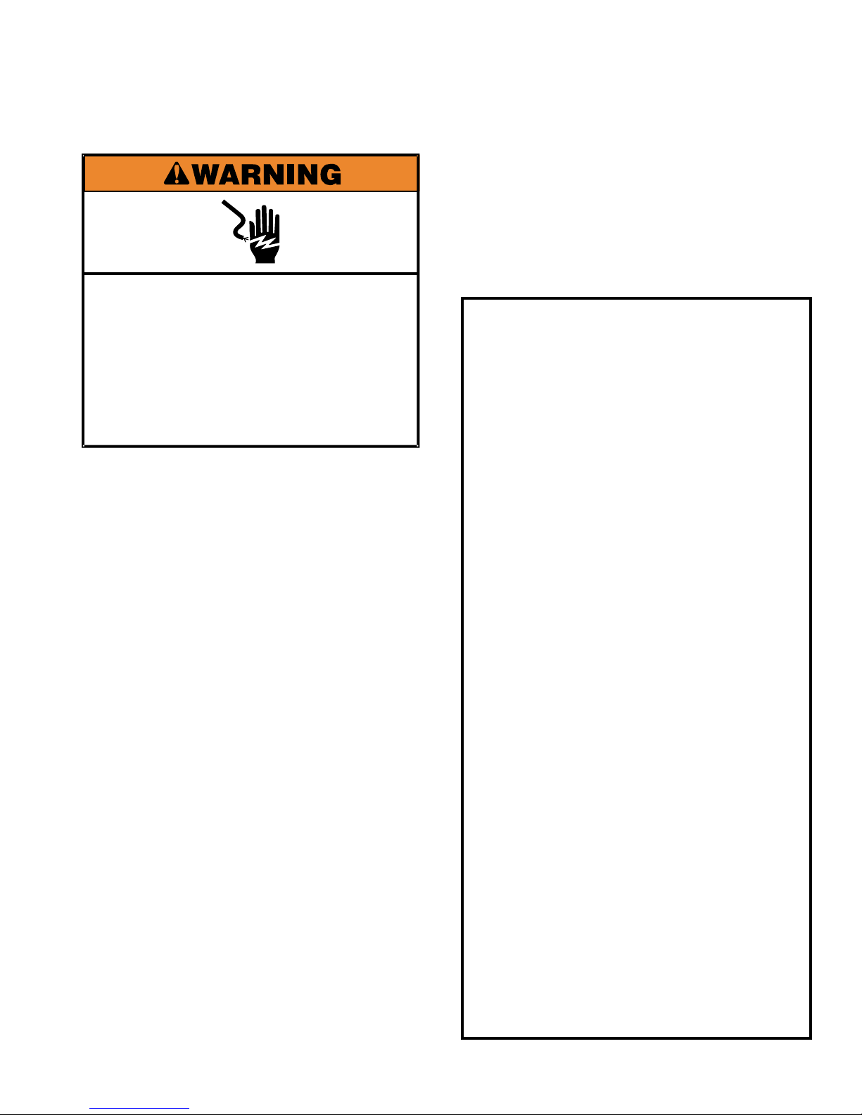
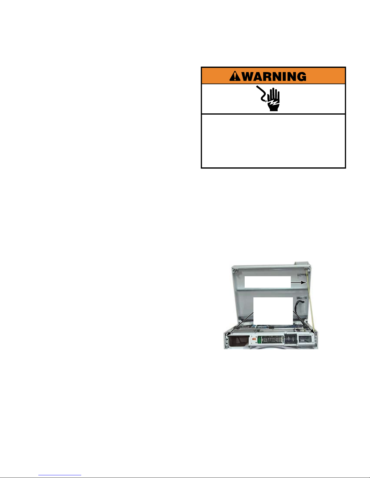
Electrical Shock Hazard
Disconnect power before servicing.
Replace all parts and panels before
operating.
Failure to do so can result in death or
electrical shock.
REMOVE SHIPPING BOLTS
Excessive Weight Hazard
Use two or more people to move and
install washer.
Failure to do so can result in back or
other injury.
WARNING
Excessive Weight Hazard
Use two or more people to move and
install washer.
Failure to do so can result in back or
other injury.
WARNING
There are 4 shipping bolts in the rear panel
1.
of the washer that support the suspension
system during transportation.
Use a 1/2” wrench to loosen each of the
2.
bolts.
Once the bolts are loose, move each one to
3.
the center of the hole and remove the bolt,
including the plastic spacer covering the
bolt.
REINSTALL SHIPPING
BOLTS
If washer must be transported after the
1.
shipping bolts have been removed, at
least 2 shipping bolts must be re-installed
to protect the washer components from
damage due to movement of the weights
and the tub.
Unplug washer or disconnect power.
2.
Turn off the water supply to the washer.
3.
Once all 4 bolts are removed, push the
4.
power cord plug into the hole in the back of
the washer and pull the cord out of the hole
at the other side.
Cover the holes that the power cord came
5.
out of with the plastic caps attached to the
back of the washer.
Pull the drain hose from inside of wash
6.
basket and install, with a clamp, on the
drain port at the top right corner of the rear
panel.
Cover the holes that the shipping bolts
7.
came out of with the plastic hole plugs
shipped with the washer.
2-6
Remove the back panel from the washer.
4.
Assemble plastic tub spacers onto shipping
5.
bolts. Insert each shipping bolt assembly
through hole in the rear brace and into the
hole in the tub. Tighten loosely with a 1/2”
wrench.
Slide shipping bolt towards the outer edge
6.
of the washer before tightening the bolt
completely to secure the spacer in place.
Reinstall the back panel before transporting
7.
the washer.
Page 19

Shown is Model MHN30PD
BASIC OPERATION
SET UP INSTRUCTIONS
This washer can hold up to an 18 lb (8.2 kg)
load of laundry.
PD Models: Insert coins until “SELECT
1.
CYCLE” flashes in display.
PR Models: A debit card is required rather
2.
than coins. In Enhanced Debit mode, the
card balance will also display when a debit
card is inserted into the reader. When set
for free vend, “SELECT CYCLE” will be
displayed.
Door must be closed before cycle selection
3.
is made.
Door locks at the beginning of a cycle and
4.
remains locked for the entire cycle.
Press fabric setting button or the wash cycle
5.
desired. After the cycle is started, the time
will display and count down.
DEBIT CARD READY: This appliance is card
reader ready. It will accept a variety of debit
card systems, but does not come with a debit
card reader. Refer to the debit card reader
manufacturer for proper washer set up. In
models converted to a Generation 1 debit
card system, a debit pulse represents the
equivalent of 1 coin.
DISPLAY: After the washer has been installed
and plugged in, the display may show
“0 MINUTES”. Once the washer has been
plugged in and the washer door opened and
closed, the display will show the price. In
washers set for free cycles, the display will
ash “SELECT CYCLE”. Otherwise the cycle
price will be displayed in dollars and cents. If
Super Cycle is enabled then the regular cycle
price and the Super Cycle price will alternate
on the display.
When a cycle is interrupted, “RESELECT
6.
CYCLE” will flash in the display. To restart
the washer, press any button.
3-1
Page 20
IMPORTANT
Electrical Shock Hazard
Disconnect power before servicing.
Replace all parts and panels before
operating.
Failure to do so can result in death or
electrical shock.
Electrostatic Discharge (ESD)
Sensitive Electronics
ESD problems are present everywhere.
ESD may damage or weaken the
electronic control assembly. The new
control assembly may appear to work
well after repair is nished, but failure
may occur at a later date due to ESD
stress.
GENERAL USER
INFORMATION
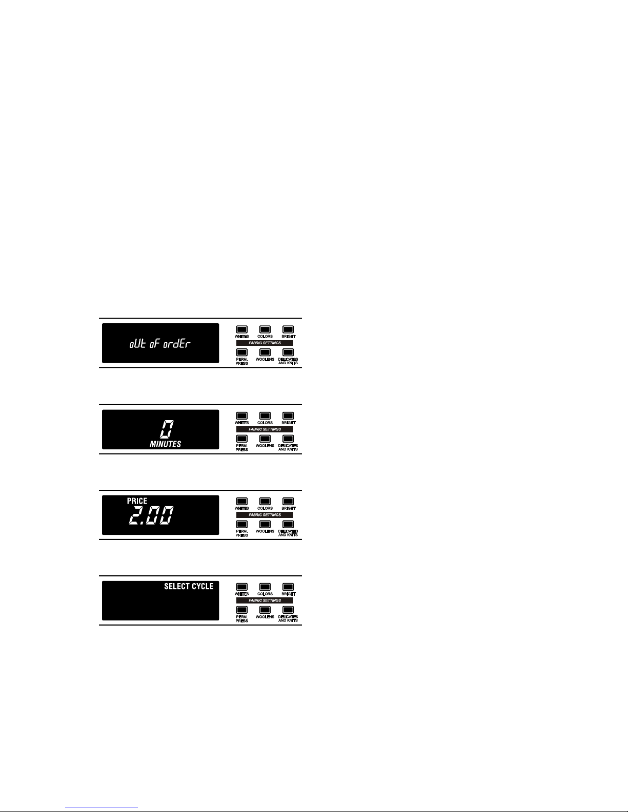
Scrolling “out of order” message followed by a
Failure Code:
This condition showing in the display indicates
the washer is in an inoperative state and
requires service. The failure code displayed is
the best indication of the reason the washer
has become inoperative.
‘0 Minutes’ showing in display:
This condition indicates the appliance cannot
be operated. Coins dropped or debit inputs
during this condition will be stored in escrow
but cannot be used until normal operation is
restored by opening and closing the door. If
a door switch has failed, it must be replaced
before normal operation can be restored.
Cold Start (initial rst use):
Appliance is programmed at the factory as
follows:
11 minute wash period
n
Use an anti-static wrist strap. Connect
n
wrist strap to green ground connection
point or unpainted metal in the
appliance.
-OR-
Touch your finger repeatedly to a green
ground connection point or unpainted
metal in the appliance.
Before removing the part from its
n
package, touch the antistatic bag to
a green ground connection point or
unpainted metal in the appliance.
Avoid touching electronic parts or
n
terminal contacts; handle electronic
control assembly by edges only.
When repackaging failed electronic
n
control assembly in antistatic bag,
observe above instructions.
3 rinses (extra rinse not enabled)
n
$1.75 wash price (PD models)
n
$0.00 wash price (PR Models)
n
Warm Start (after power failure):
A few seconds after power is restored, if a
cycle was in progress at the time of the power
failure, ‘RESELECT CYCLE’ will ash in the
display, indicating the need for a button press
to restart the washer.
3-2
Page 21
Door Lock
NOTE: Not displayed on washer as shown. Message scrolls
followed by the failure code.
Door lock does a Child Safety Routine at start
of every cycle. Child Safety Routine is: Lock,
turn spin basket 1/2 revolution, Unlock, then
Relock. The door will be locked when the
cycle starts. The door will remain locked until
the end of a cycle or approximately 2 minutes
after a power interruption.
NOTE: If power is interrupted prior to 2
minutes of operation the automatic door
unlocking mechanism may fail, and door will
remain locked until the power is restored or
the lock is manually opened by pulling on the
safety release tab.
(See page 4-17)
Free Cycles
This is established by setting the cycle price to
zero. When this happens, ‘SELECT CYCLE’
will be displayed rather than a cycle price.
Debit Card Ready
This washer is debit card ready. It will accept
a variety of debit card systems, but
DOES NOT come with a debit card reader.
Refer to the debit card reader manufacturer for
proper washer set-up. In models converted to
a Generation 1 debit card system, each debit
pulse represents the equivalent of one coin
(Coin 1).
Display
After the washer has been installed and
plugged in, the display may show
‘0 MINUTES’. Once the washer has been
plugged in and the washer door opened and
closed, the display will show the cycle price
or amount of coins needed to start a cycle. If
Super Cycle is enabled the Regular price and
Super Cycle price will alternate in the display.
In washers set for free vend, the display will
ash ‘SELECT CYCLE’ rather than a cycle
price.
Pricing in the display
After the door is opened following the
completion of a cycle, the display indicates the
cycle price (unless set for free operation). As
coins are dropped or debit inputs arrive, the
display will change to lead the user through
the initiation of a cycle.
During a cycle the display will show the
approximate time remaining unless the
washer is going through a “Suds Removal
Routine.” During the routine the display will
alternate between the word “SudS” and the
time remaining in the routine. At the end of
the 5 minutes needed for this routine, the
display returns to the same time displayed
prior to entering it.
3-3
Page 22

CONTROL SET-UP PROCEDURES
IMPORTANT: Read all instructions before
operating.
PD Models: Use service key to remove
n
service access door. Lifting the service
access door engages the service switch.
PR Models: Once a Generation - 2 debit
n
card reader is installed (according to the
reader manufacturer’s instructions), the
set-up codes can be changed by inserting
a manual set-up card (supplied by the
reader manufacturer) into the card slot or
by the use of a handheld device with DA
communication and AccuTrac software. If a
manual set-up card or a handheld AccuTrac
device is not available, only diagnostic
mode can be entered by removing the
connector AA1 on the circuit board.
PR Models set up as PNs :
n
Service Access Code: This code can be
entered to access service mode without
removing the console. It only functions on
washers set up for 0 vend price without any
Special Pricing set-up, and the Coin/Debit
Option must be set to “J._d”. If the washer
is not in failure mode, the door must be
opened to proceed. Service Access Code
contains 6 steps and some are timed. Using
only the three bottom buttons (numbered 1,
2, and 3 from left to right):
Press 2 for longer than 2 seconds but less
1.
than 10 seconds.
Press 1 & 3 together for 2 seconds, then
2.
release. Displays S 3.
Press 1 & 2 together, then release.
3.
Displays S 4.
Press 2 & 3 together, then release.
4.
Displays S 5.
Press 2, then release.
5.
Displays “codE”.
Wait at least 2 seconds, but not more than
6.
15 seconds, then press in succession:
3, 2, 1, 3.
NOTE:
is not completed properly, as noted above,
there is a 15 second delay before it can be
attempted again.
n
1.
2.
3.
If the Service Access Code procedure
There are 3 options to exit from the Service
Mode when the Service Access code has
been used to enter it:
From Set-up Code 8, press PERM. PRESS
for 4 seconds.
Wait 2 minutes without touching any buttons
(without diagnostic modes running).
Power down the washer, then reapply
power.
3-4
Page 23

REMOVE AA1 JUMPER
PR Models Only:
IMPORTANT: Unplug washer or disconnect
power before opening the console to access
connector AA1:
Unplug washer or disconnect power.
Ë
Open console, remove and retain plug on
Ë
AA1, close console.
Plug in washer or reconnect power.
Ë
The washer is now in the set-up mode. The
lower fabric setting key pads and the digital
display are used to set up the controls. The
control can display 4 numbers and/or letters
and a decimal point. These are used to
indicate set-up codes and related code values
available for use in programming the washer.
How to use the key pad to program the
controls
Start Operating Set-Up
Before proceeding, it is worth noting that,
despite all of the options available, an
owner can simply choose to uncrate a new
commercial washer, add appropriate payment
device or OPL Kit as needed and a service
lock for PD models, plug it in, and have a
washer that operates. Washers are preset at
the factory for a 11-minute wash period and 3
rinses (no extra rinse).
The PERM. PRESS button is used to
1.
adjust the values associated with set-up
codes. Pressing and releasing the button
will change the value by increments. Rapid
adjustment is possible by holding the button
down.
The DELICATES AND KNITS button
2.
advances the display through the set-up
codes. Pressing the button will advance
to the next available set-up code. Holding
the button down will automatically advance
through the set-up codes at a rate faster
than 1 per second.
The QUICK CYCLE button is used to select
3.
or deselect options.
3-5
Page 24
SET-UP CODES
NOTE: First code shown in each section is default code for coin equipment.
CODE EXPLANATION
R
EGULAR CYCLE PRICE
Represents the number of quarters needed to start the washer(coin 1
)
;
may adjust from 0-39. (SeeVALUE OF COIN 1.) Advance from 0-39 by
pressing the PERM. PRESS key pad. Factory default of 7 quarters = $1.75.
PR MODELS ONLY: Factory default of 0 quarters .
With coin slide activation,this represents the number of push-in
actuations of a coin slide to start the washer.
6 01 setting would represent one coin slide actuation.
NOTE: For coin slide activation, replacement of themeter case is necessary.
�
Press the DELICATES AND KNITS key pad once to advance to next code.
6 0
7
6 0 7
6 00
(coin 1
)
CODE EXPLANATION
WASH LENGTH
This is the number of minutes for WASH. Washer comes from the
factory preset with 11 minutes. Choose from 9-17 minutes by
p
ressing the PERM. PRESS key pad. Wash time does not include
fill time.
�
Press the DELICATES AND KNITS key pad once to advance to next code.
ADDITIONAL RINSE OPTION
This option is either SELECTED ‘ON’ or NOT SELECTED ‘OFF’.
Not Selected ‘OFF’.
S
elected ‘ON’.Cannot be combined with the Super Cycle rinse option.
Press the QUICK CYCLE key pad once for this selection.
�
Press the DELICATES AND KNITS key pad once to advance to next code.
CYCLE COUNTER OPTION
This option is either SELECTED ‘ON’ or NOT SELECTED ‘OFF’.
Not Selected ‘OFF’.
Selected ‘ON’ and not able to be deselected.
Press the QUICK CYCLE key pad 3 consecutive times to select
‘ON’. Once selected ‘ON’ it cannot be deselected.
�
Press the DELICATES AND KNITS key pad once to advance to next code.
MONEY COUNTER OPTION
This option is either SELECTED ‘ON’ or NOT SELECTED ‘OFF’.
Not Selected ‘OFF’.
Selected ‘ON’.
Press the QUICK CYCLE key pad 3 consecutive times
to select‘ON’ and 3 consecutive times to deselect (Not
Selected ‘OFF’.) Counter resets by going from ‘OFF’ to ‘ON’.
Selected ‘ON’ and not able to be deselected.
To select ‘ON’ and not able to be deselected,first select ‘ON’,
then within two seconds press the QUICK CYCLE key pad twice,
the PERM. PRESS key pad once,and exit the set-up mode.
�
Press the DELICATES AND KNITS key pad once to advance to next code.
SPECIAL PRICING OPTION
This option is either SELECTED ‘ON’ or NOT SELECTED ‘OFF’.
Not Selected ‘OFF’, and next available code will be A.00.
Selected ‘ON’. Press the QUICK CYCLE key pad once
for this selection.
If SPECIAL PRICING OPTION is selected, you have access to codes ‘3.XX’
through ‘9.XX’.
�
Press the DELICATES AND KNITS key pad once to advance to next code.
7 1 1
7 1 1
9 0 0
9 0 0
9 0
C
1.0 0
1.0 0
1.0
C
1.C0
2.0 0
2.0 0
2.
S P
OPTIONSTOUSE IF SPECIAL PRICING IS SELECTED:
SPECIAL CYCLE PRICE
Represents the number of quarters (coin 1) to start a cycle:
may adjust from 0-39. (See VALUE OF COIN 1.) Advance from
0-39 by pressing the PERM. PRESS key pad. Factory default
of 7 quarters = $1.75.
PR MODELS ONLY: Factory default of 0 quarters.
�
Press the DELICATES AND KNITS key pad once to advance to next code.
3. 0 7
3. 0 7
3. 0 0
8 0 0
8 0 0
8A8
The DELICATES AND KNITS button will
n
advance from code to code.
The PERM. PRESS button will change the
n
code value.
The QUICK CYCLE button will select or
n
deselect options.
FOR PR MODELS: The set-up codes are the
same as for the ‘PD’ models except where
noted.
The set-up code is indicated by the one or two
left-hand characters. The set-up code value
is indicated by the two or three right-hand
characters. NOTE: First code shown in each
section is default code for coin equipment.
3-6
Page 25
C
ODE EXPLANATION
OPTIONS TO USE IF SPECIAL PRICING IS SELECTED (cont.):
TIME-OF-DAY CLOCK, MINUTES
This is the TIME-OF-DAY CLOCK, minute setting; select 0-59
m
inutes by pressing the PERM.PRESS key pad.
�
Press the DELICATES AND KNITS key pad once to advance to next code.
TIME-OF-DAY CLOCK, HOURS
N
OTE: Uses military time or 24 hr. clock.
This is the TIME-OF-DAY CLOCK, hour setting; select 0-23 hours
by pressing the PERM.PRESS key pad.
�
P
ress the DELICATES AND KNITS key pad once to advance to next code.
SPECIAL PRICE START HOUR
NOTE: Uses military time or 24 hr. clock.
This is the start hour; 0-23 hours. Select START HOUR by pressing
the PERM.PRESS key pad.
�
Press the DELICATES AND KNITS key pad once to advance to next code.
SPECIAL PRICE STOP HOUR
NOTE: Uses military time or 24 hr. clock.
This is the stop hour; 0-23 hours. Select STOP HOUR by pressing
the PERM.PRESS key pad.
�
Press the DELICATES AND KNITS key pad once to advance to next code.
SPECIAL PRICE DAY
This represents the day of the week and whether special pricing
is selected for that day. A number followed by ‘0’ indicates no
selection that particular day (9.10). A number followed by an ‘S’
indicates selected for that day (9.1S). To change the value of ‘0’
and ‘S’, use the QUICK CYCLE key pad.
Days of the week (1-7) are selected by pressing the PERM.
PRESS key pad.
When exiting set-up code ‘9’, the display must show current day
of week:
DISPLAY DAY OF WEEK CODE (selected)
10 Day 1 = Sunday 1S
20 Day 2 = Monday 2S
30 Day 3 = Tuesday 3S
40 Day 4 = Wednesday 4S
50 Day 5 = Thursday 5S
60 Day 6 = Friday 6S
70 Day 7 = Saturday 7S
�
Press the DELICATES AND KNITS key pad once to advance to next code.
8.0 0
8.0 0
9. 1 0
9. 1 0
VAULT VIEWING OPTION
This option is either SELECTED ‘ON’ or NOT SELECTED ‘OFF’.
Not Selected ‘OFF’.
Selected ‘ON’. Press the QUICK CYCLE key pad once for
this selection.When selected, the money and/or cycle counts
will be viewable (if counter option(s) is selected) when the coin
box is removed.
�
Press the DELICATES AND KNITS key pad once to advance to next code.
VALUE OF COIN 1
This represents the value of coin 1 in number of nickels:
05 = $0.25.
By pressing the PERM.PRESS key pad, you have the option
of 1-199 nickels.
With coin slide activation,this represents the total vend price
in nickels. Example: b.30 is equal to $1.50.
�
Press the DELICATES AND KNITS key pad once to advance to next code.
A.
00
A.
00
6.0 5
6.0 5
A.SC
C
ODE EXPLANATION
VALUE OF COIN 2
This represents the value of coin 2 in number of nickels:
20 = $1.00.
PR MODELS ONLY: Factory default of $0.25.
By pressing the PERM. PRESS key pad, there is the option
of 1-199 nickels.
�
Press the DELICATES AND KNITS key pad once to advance to next code.
COIN SLIDE OPTION
This option is either SELECTED ‘ON’ or NOT SELECTED ‘OFF’.
R
eplacement of meter case will be needed for coin slide mounting.
Not Selected ‘OFF’.
NOTE: This option needs to be set to “00” unless the meter case
has been changed to accept a coin slide device.
Selected ‘ON’. Press the QUICK CYCLE key pad 3 consecutive
times for this selection.
When coin slide mode is selected, set ‘b.’ equal to value of vend price
in nickels.Set set-up code 6 xx (regular cycle price) and set-up code
3.xx (special cycleprice) to number of slide operations.If the installer
sets up ‘CS’ on a model with a coin drop, it will not register coins.
�
Press the DELICATES AND KNITS key pad once to advance to next code.
ADD COINS OPTION
This option is either SELECTED ‘ON’ or NOT SELECTED ‘OFF’. This
option causes the customer display to show the number of coins
(coin 1) to enter, rather than the dollars-and-cents amount.
Not Selected ‘OFF’.
Selected ‘ON’. Press the QUICK CYCLE key pad 3 consecutive
times for this selection.
�
Press the DELICATES AND KNITS key pad once to advance to next code.
ENHANCED PRICING OPTION
Not Selected ‘OFF’.
Cycle-Based pricing enabled. This option allows configuration
of different prices for cold, warm, and hot water cycles.
Super Cycle pricing enabled.This option allows customers
to upgrade cycles by depositing extra money. Set-up codes
‘H.’ and ‘h.’ will be displayed only when this option is enabled.
Press the QUICK CYCLE key pad for this selection.
�
Press the DELICATES AND KNITS key pad once to advance to next code.
SUPER CYCLE UPGRADE PRICE
(Skipped unless Super Cycle pricing is enabled.)
This represents the number of coin 1 required to upgrade a
base cycle to a super cycle. Advance from 0-39 by pressing
the PERM. PRESS key pad.
�
Press the DELICATES AND KNITS key pad once to advance to next code.
SUPER CYCLE TYPE
(Skipped unless Super Cycle pricing is enabled.)
This represents the Super Cycle upgrade option.Press the
PERM. PRESS key pad to step through upgrade options 1
through 3 as follows:
01 - enhanced wash, extra 3 minutes of wash tumble in addition
to the programmed wash time.
02 - extra rinse for all cycles.
03 - both 01 and 02.
�
Press the DELICATES AND KNITS key pad once to advance to next code.
8.0 0
E
. 0 0
E
. 0 0
E.A C
8.0 0
8.
CS
F
. 0 0
F
. 0 0
F.CP
F.S
8
H
.0 1
H
.0 1
H
.0 1
H
.0 1
5.0 0
5.0 0
6.0 0
6.0 0
7.0 0
7.0 0
C
.20
C
.20
C
.05
3-7
Page 26
If cycle counter (9 0C) is selected, the
CODE EXPLANATION
COIN/DEBIT OPTION
Both coin & debit selected.
Coins selected, debit disabled. Press the QUICK CYCLE key pad
3 consecutive times to change this selection.
PR models factory default to J._d. Debit Card selected, coins
disabled. Press the QUICK CYCLE key pad 3 consecutive times
to change this selection.
Enhanced Debit is self-selected when a Generation 2 card reader
is installed in the washer.The Ed option cannot be manually
selected or deselected.
�
Press the DELICATES AND KNITS key pad once to advance to next code.
PRICE SUPPRESSION OPTION
This option causes the customer display to show‘ADD’ or
‘AVAILABLE’ rather than the amount of money to add. (Used
mainly in debit installations.)
Not Selected ‘OFF’.
Selected ‘ON’.Press the QUICK CYCLE key pad once
for this selection.
�
Press the DELICATES AND KNITS key pad once to advance to next code.
CLEAR ESCROW OPTION
When selected, money held in escrow for 30 minutes without
further escrow or cycle activity will be cleared.
Not selected ‘OFF’.
Selected ‘ON’.Press the QUICK CYCLE key pad once to change
this selection.
�
P
ress the DELICATES AND KNITS key pad once to advance to next code.
TOP SPIN SPEED RPM
This can be selected from the following spin speeds: 600 rpm,
750 rpm, 800 rpm, 1000 (displays as 999) rpm.Step between
speeds by pressing the PERM.PRESS key pad. Factory
default of 800 rpm.
�
Press the DELICATES AND KNITS key pad once to advance to next code.
P
ENNY INCREMENT OFFSET
This represents the penny increment price offset used in
Generation 2 (Enhanced Debit) PR models. Choose from 0-4
pennies by pressing the PERM. PRESS key pad.
�
Press the DELICATES AND KNITS key pad once to advance to next code.
PREWASH LENGTH
This is the number of minutes of PREWASH. Choose 0 to disable
the prewash or select between 2 and 7 minutes by pressing the
PERM. PRESS key pad.
�
Press the DELICATES AND KNITS key pad once to advance to next code.
FINAL SPIN LENGTH
This is the number of minutes of final high speed spin. Choose
from 3-8 minutes by pressing the PERM.PRESS key pad.
�
Press the DELICATES AND KNITS key pad once to advance to next code.
J.C
8
L
. 0 0
L
. 0 0
L.PS
8.
C E
J.C
8
J.C
8
J.C
8
J.E
8
8.
C E
8.00
0.0 0
0.0 0
8.8
00
8.800
8 1. 0 0
8 1. 0 0
82.03
82.03
following is true:
1 00 Cycles in Hundreds 1 02 = 200
2 00 Cycles in Ones 2 25 = 25
TOTAL CYCLES = 225
This is “VIEW ONLY” and cannot be cleared.
Press the DELICATES AND KNITS button
once to advance to next code.
_____________________________________
If money counter (1.0C or 1.C0) is selected,
the following is true:
3 00 Dollars in Hundreds 3 01 = $ 100.00
4 00 Dollars in Ones 4 68 = $ 68.00
5 00 Number of Cents 5 75 = $ .75
TOTAL = $ 168.75
END OF SET-UP PROCEDURES
_____________________________________
EXIT FROM MANUAL SET-UP MODE
PD Models: Reinstall service access door
n
PR Models: Remove Smart Card
n
PR Models without card reader installed:
n
Unplug washer or disconnect power.
Ë
Open console, reinsert plug into AA1,
Ë
close console.
Plug in washer or reconnect power.
Ë
PR Models set up as PN with programming
n
switch: Turn key clockwise and remove.
PR Models set up as PN without
n
programming switch: Set-up mode can be
exited by using procedures from Service
Access Code (See page 3-4).
3-8
Page 27
COMPONENT ACCESS
COMPONENT ACCESS
COMPONENT LOCA
TIONS
This section shows how to service each component within the Whirlpool Commercial Front
Loading W
ashers Model 8990. The components and their locations are shown below.
RFI Line Filter
Rear Panel
Ground Switch
T
ub-To-Pump
Hose
Front Panel
Ground Switch
Drive Motor
2 of 3
Air Gap
Dampers
Spin Basket
T
emperature Sensor:
(On rear of outer tub)
Chemical
Dispenser
&
Assembly
Dual Cold W
ater
Inlet Valve
Single Hot W
ater
Inlet Valve
Not Shown:
Key pad
Assembly,
User Interface Control
Transformer and
Door Latch Assembly
Central
Control Unit
Pressure
Switch
Pump-T
o-Drain
Hose
V
ent Tube
Motor Control
Unit
Outer
Tub
Assembly
Drain Pump
Filter
Drain Pump
Motor
Drain Pump
COMPONENT LOCATIONS
This section shows how to service each component within the Maytag Model 30 Commercial Front
Loading Washer. The components and their locations are shown below.
4-1
Page 28

CHEMICAL DISPENSER
Electrical Shock Hazard
Disconnect power before servicing.
Replace all parts and panels before
operating.
Failure to do so can result in death or
electrical shock.
REMOVE FACIA AND
DRAWER AND PARTS
Pull the drawer out as far as it will go and
1.
press the release tab down in the top left
rear corner with a flat blade screwdriver.
Pull the drawer out of the washer.
2.
CONTROL PANEL COVER
Unplug washer or disconnect power.
1.
Turn off the water supply to the washer.
2.
Remove four T-20 security machine screws
3.
from the front of the facia.
Lift the detergent cup insert out of the
3.
detergent drawer for cleaning.
Remove the locking tab by unclipping it from
4.
the slots in the top left rear corner. Replace
it by clipping it into the slots.
Remove front decorative plate by removing
5.
four T-20 security sheet metal screws.
TECH TIP:
The decorative front plate is secured with
n
sheet metal screws. The facia is secured
with machine screws. Do not interchange
these screws.
The front of the chemical dispenser drawer
n
is called the handle, and it can come off if
pulled on too hard. To reinstall the handle
straighten the tabs, hook the top 3 tabs
onto the drawer and rotate the front down to
engage 3 tabs at the bottom.
If softener fails to dispense properly or
n
completely, remove the bottom cover of
the dispenser assembly and make sure the
siphon holes are clean.
4-2
Remove the chemical dispenser drawer
4.
from the washer.
Remove two T-20 security sheet metal
5.
screws, that were hidden by the chemical
dispenser drawer, on the left end of the
control panel.
Two T-20
Security Screws
Page 29
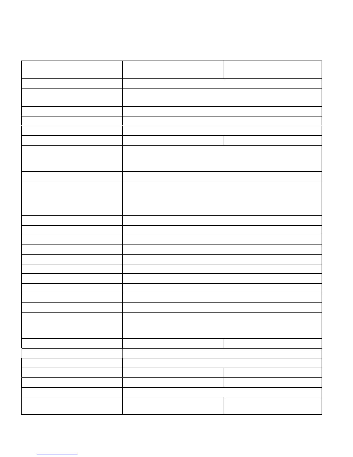
Pull the control panel cover, facia and
Electrical Shock Hazard
Disconnect power before servicing.
Replace all parts and panels before
operating.
Failure to do so can result in death or
electrical shock.
6.
display lens off the washer.
Depress the clips on the edges of the
7.
display lens on the back side of the control
panel cover. Remove the display lens from
the front of the cover.
On PR Models the card reader cover has
8.
two clips on the back side of the control
panel cover that hold it in place. Depress
the clips and remove the cover, along with
the facia, from the front of the control panel
cover.
Unclip the two clips from the back side of
9.
the facia and remove the card reader cover
from the front of the facia.
NOTE: To avoid damage, lay a towel, or
another covering, on the washer top and
place removed hardware and tools on the
covering.
LIFT WASHER TOP
Unplug washer or disconnect power.
1.
Turn off the water supply to the washer.
2.
Remove the control panel cover
3.
(See page 4-2).
Remove two 1/4” hex head screws, one
4.
in each top front corner behind the control
panel cover.
TECH TIPS:
Machine screws must be used for the facia,
n
not sheet metal screws.
In the opening for the card reader is the
n
cable for a card reader that is now installed
on the control board at the factory.
There is a wire harness in the card reader
n
opening that is connected to the edge of the
UIC used in the manufacturing process only.
It can be left in the control panel or removed
if desired.
4-3
Support Rod
Two 1/4”
Hex Head
Screws
Lift the front edge of the washer top to open
5.
it. When it is open all the way it will rest
on the 2 retaining supports attached to the
back of the washer just below the top.
NOTE: If the washer is not level the top may
not be stable to leave in the upright position
without using a support rod.
The top has 2 hinges, secured with star
6.
head screws, that are hidden once the top is
closed.
Page 30
Electrical Shock Hazard
Disconnect power before servicing.
Replace all parts and panels before
operating.
Failure to do so can result in death or
electrical shock.
REMOVE CONTROL PANEL
Unplug washer or disconnect power.
1.
Turn off the water supply to the washer.
2.
Lift the washer top (See page 4-3).
3.
Remove two T-20 1/4” hex head screws on
4.
each end that secure the control panel to
the washer.
Rotate the control panel down to access the
6.
components located behind it.
Disconnect the power connector from
7.
the transformer at AA6 on the UIC, by
depressing the tab and pulling the plug off
of the connector.
Disconnect the wire harness from the CCU
8.
to the UIC by depressing the locking tab
and pulling the Rast connector off of the
control board edge.
Each Rast connector has keyed tabs on
9.
the top, which are located in different
places on each connector to assist in
proper placement of the connector during
reassembly.
Disconnect the ground wire from the
10.
control panel by depressing the locking
tab and pulling the connector off the spade
which is secured to the control panel with a
screw.
Left end
Four T-20 1/4”
Hex Head
Screws
Lift the control panel up to release the two
5.
tabs from the top edge of the washer.
2 Tabs
Right end
4-4
The control panel can now be removed
11.
from the washer.
The control panel has brass inserts in
12.
the screw holes that can be removed and
changed if they become stripped. The
brass inserts are threaded on the outside
and on the inside. Use a pair of pliers to
unscrew the insert from the control panel.
CCU to UIC
Rast Connector
Transformer
Connector AA6
NOTE: CCU to UIC cable can be
connected to either of the top 2 connections
on the UIC edge. (WB3 or WA3).
Ground Wire
Connector
Page 31

Electrical Shock Hazard
Disconnect power before servicing.
Replace all parts and panels before
operating.
Failure to do so can result in death or
electrical shock.
REMOVE USER INTERFACE CONTROL (UIC)
Squeeze the 2 tabs at the left end of the
7.
board together and lift the board up off the
squeeze tabs. Remove the board by sliding
it out of the control board edge connector
mounting bracket.
Unplug washer or disconnect power.
1.
Turn off the water supply to the washer.
2.
Remove the control panel (See page 4-4).
3.
Disconnect all of the wire connectors from
4.
the UIC.
Remove the key pad assembly ribbon
5.
connector by gently pulling it out of the
connector GG5 on the board.
2 Star Head
Screws
2 Tabs
Two 5/16”
Nuts
Push Button
Ribbon Cable
Remove the 2, number 1, star head screws
6.
from the left end and two 5/16” nuts from
the right end of the UIC.
4-5
Page 32

Electrical Shock Hazard
Disconnect power before servicing.
Replace all parts and panels before
operating.
Failure to do so can result in death or
electrical shock.
REMOVE KEY PAD ASSEMBLY
Unplug washer or disconnect power.
1.
Turn off the water supply to the washer.
2.
Remove the control panel (See page 4-4).
3.
Press the end of the bolts down and remove
7.
the key pad assembly from the front side of
the control panel.
NOTE: Key pad assemblies may look
similar across Maytag product lines, but
the hardware may be different and not
interchangeable.
Remove two 5/16” hex head nuts from the
4.
right end of the UIC.
Two 5/16”
Nuts
Ribbon
Connector
Gently pull the ribbon connector out of the
5.
connector GG5 on the UIC.
The extra length of plastic at the end of the
6.
ribbon connector must be bent back over
the top of the end of the ribbon connector,
not down and under or it will block the
connections preventing operation. (See first
picture in next column)
To remove the buttons from the
8.
subassembly, release the locking tab that
holds each row of push buttons on the back
side of the subassembly. The other end
simply slides out of the slot in the metal
backer plate.
Slot
Tab
Tab
Slot
The electronic membrane pad is glued to
9.
the metal plate of the subassembly and
cannot be separated.
4-6
Page 33

Electrical Shock Hazard
Disconnect power before servicing.
Replace all parts and panels before
operating.
Failure to do so can result in death or
electrical shock.
REMOVE CONTROL PANEL BRACKET
Unplug washer or disconnect power.
1.
Turn off the water supply to the washer.
2.
Disconnect the transformer primary wire
6.
harness connector from near the CCU.
Push the free end of wires from the control
7.
panel through the hole in the control panel
bracket and remove the bracket.
Transformer
Wire Harness
Connector
Control Panel
Bracket
CCU
Remove the control panel (See page 4-4).
3.
Remove three 1/4” hex head screws at each
4.
end of the bracket.
Remove two T-20 screws from the control
5.
panel bracket that secure the front and top
of the chemical dispenser.
NOTE: These screws have higher, wider
spaced threads that are made for holding
tightly to plastic. The head shape on these
two screws is also different, a round flat top,
for easy identification.
Three 1/4” Hex
Head Screws
Free End Of Wires
From Coin Meter
Two T-20
Screws
4-7
Page 34

Electrical Shock Hazard
Disconnect power before servicing.
Replace all parts and panels before
operating.
Failure to do so can result in death or
electrical shock.
REMOVE CENTRAL CONTROL UNIT (CCU)
Unplug washer or disconnect power.
1.
With a small flat blade screwdriver, lift the
6.
locking tab that secures the CCU to the
washer.
CCU Locking tab
Turn off the water supply to the washer.
2.
Lift the washer top (See page 4-3).
3.
Remove two 1/4” hex screws to remove the
4.
cross brace below the top (See page 4-46).
Use a small flat blade screwdriver to press
5.
on the locking tab that secures each wire
connector to the CCU, and remove the
connectors.
Central
Control Unit
Transformer
Connection
Slide the CCU towards the back of the
7.
washer to release the tabs from the keyhole
slots in the side panel of the washer and
remove it.
Wire Clamps
Keyhole Slots
CCU Tabs
4-8
Page 35

CCU CONNECTIONS
Ensure that
connectors are rmly seated
onto the circuit board edge, and that the
locks are properly engaged.
S
e
riel Port
Not Used
PR6 - Pressure Switch
6 BU Wires
D
S2 - Door Switch
2 BU Wires
Blue Stripe
4 BU Wires
RD Stripe
DP2 - Drain Pump
2 BK Wires
BK Stripe
DL3 - Door Lock
3 BK Wires
GN Stripe
4 BU Wires
BU Stripe
TH2 - Temp Sensor
2 BK Wires
No Stripe
MI3
3 BU Wires
MS2 - Drive Motor
WH Stripe
DLS2 - Door Lock Switch
IF2 - Line Filter
(2 Pink Wires)
Board Edge Connectors
Connector Locking Tabs
CENTRAL CONTROL
UNIT
Not Used
MCU Interface
HE2 - Wax Moto
r
Not Used
User Interface
MS2-MCU
(Drive Motor Power)
3 BK Wires
GN Stripe
DI6 -
Hot W
ater Inle
t #1
VC
H7
- Cold W
ater Inlet 2
- Cold W
ater Inle
t #3
DL3'
'-'''Doorq***** Lock ''''Sol'%enoi%%d
(L1 is on the right)
4-9
Page 36

Electrical Shock Hazard
Disconnect power before servicing.
Replace all parts and panels before
operating.
Failure to do so can result in death or
electrical shock.
REMOVE WATER INLET VALVES
Locking Tab
Unplug washer or disconnect power.
1.
Turn off the water supply to the washer.
2.
Remove the washer hoses from the hot and
3.
cold water inlet valves.
Lift the washer top (See page 4-3).
4.
Water Inlet
Valves
Lift The locking tabs and disconnect the
5.
wire connectors to the water inlet valves.
The blue connector is for the hot water
valve number 1, the white connector is for
cold water valve number 3 and the grey
connector is for cold water valve number 2.
Inlet Hoses
& Clamps
Remove the T-20 screw, on the back of the
7.
washer, that secures each water inlet valve.
From inside of the washer, twist the valve
8.
body to align the locking tabs with the cutouts in the back panel. Pull the valve out of
the hole in the panel.
Water Inlet
Valve Screws
The screens inside the water inlet valve
9.
can be cleaned from the rear of the washer
without removing the water inlet valve.
NOTE: (See page 4-35) for photos and for
how to remove the water inlet valves from
the back.
Loosen the clamp and disconnect the hose
6.
from each water inlet valve.
4-10
Page 37

Electrical Shock Hazard
Disconnect power before servicing.
Replace all parts and panels before
operating.
Failure to do so can result in death or
electrical shock.
REMOVE PRESSURE SWITCH
Unplug washer or disconnect power.
1.
Rotate the pressure switch 45 degrees and
5.
pull the rectangular tab out of the slot in the
top of the washer side panel.
Pressure
Switch
Wire
Harness
Turn off the water supply to the washer.
2.
Lift the washer top (See page 4-3).
3.
Pressure
Switch
Disconnect the wire harness by pressing the
4.
locking tabs and pulling the wire harness off
the pressure switch.
Air Hose
Disconnect the air hose on the bottom of the
6.
pressure switch, there is no clamp, just a
pressure fit.
NOTE: Hose should be snug to avoid air
leaks.
Slot
Key
4-11
Page 38

Electrical Shock Hazard
Disconnect power before servicing.
Replace all parts and panels before
operating.
Failure to do so can result in death or
electrical shock.
REMOVE RFI LINE FILTER
Unplug washer or disconnect power.
1.
Turn off the water supply to the washer.
2.
Lift the washer top (See page 4-3).
3.
T-20 Screw
4 Tabs In Slots
RFI Line Filter
Press The locking tab and remove the
7.
connector for the pink wires.
Pull the black and white wire connectors off
8.
their spade terminals.
RFI Line
Filter
Remove the T-20 1/4” hex head screw. (See
4.
first picture in next column)
Slide the RFI line filter to the left to release
5.
the tabs in the slots.
Power goes into the RFI line filter through
6.
the black (hot) wire and white (neutral) wire
connectors. Power goes out to the CCU
through the pink wires.
White (Neutral)
Black (Hot)
NOTE:
if the AC power is connected with reverse
polarity. When properly installed the White
(neutral) wire connector should be toward the
front of the washer as viewed from the RFI
lters installed orientation.
To test for proper polarity, power must be
reconnected to the washer, test between the
white (neutral) wire connector and any chassis
ground connection with a volt meter. If the
polarity is correct there should be no voltage
present. Disconnect the washer from the
power before proceeding.
Problems can occur with this washer
4-12
Pink Wires
Out To CCU
Page 39

Electrical Shock Hazard
Disconnect power before servicing.
Replace all parts and panels before
operating.
Failure to do so can result in death or
electrical shock.
REMOVE POWER SUPPLY CORD
Unplug washer or disconnect power.
1.
Turn off the water supply to the washer.
2.
Lift the washer top (See page 4-3).
3.
Ground Wire Screw
2 Wire
Connectors
Push the wire connectors out the rear panel
8.
of the washer.
Remove the screw from the green ground
4.
wire. (See first picture in next column)
Pull the connectors with white and black
5.
wires from the RFI line filter terminals.
RFI Line
Filter
Pull the washer away from the wall far
6.
enough to access the power supply cord on
the rear panel.
1/4” Hex
Head Screw
Remove the one 1/4” hex head screw that
7.
secures the power supply cord strain relief
to the rear panel of the washer.
4-13
Page 40

Electrical Shock Hazard
Disconnect power before servicing.
Replace all parts and panels before
operating.
Failure to do so can result in death or
electrical shock.
REMOVE CHEMICAL DISPENSER ASSEMBLY
Unplug washer or disconnect power.
1.
Turn off the water supply to the washer.
2.
Remove the control panel bracket
3.
(See page 4-7).
Remove two 1/4” hex screws to remove the
4.
cross brace below the top
(See page 4-46).
Remove the hoses to the water inlet valves
5.
from the back of the chemical dispenser.
Make note which hose is connected to
which inlet.
Slide the chemical dispenser toward the
7.
rear of the washer to release the tab that
secures it to the left side panel.
Keyhole
Slot
Main Water
Inlet Tube
Remove the clamp that secures the main
8.
water inlet tube to the bottom left front
corner of the chemical dispenser and
remove the hose.
REASSEMBLY NOTE: When reconnecting
the main water inlet tube, align the arrow
on the tube with the line on the chemical
dispenser. Align the arrow on the flanged
end of the tube with the arrow on the tub at
approximately the 1:00 position.
Line On
Arrow On
Tube
Chemical
Dispenser
Tab
There is a water metering insert in the end
6.
of this hose. Remove it, if necessary, by
pulling it out of the end of the hose.
Water Inlet
Valve Hoses
Chemical
Dispenser
Cross
Brace
Arrow On
Flanged End
4-14
Page 41

Arrow
Electrical Shock Hazard
Disconnect power before servicing.
Replace all parts and panels before
operating.
Failure to do so can result in death or
electrical shock.
On Tub
REMOVE TRANSFORMER
Unplug washer or disconnect power.
1.
Turn off the water supply to the washer.
2.
Arrow On
Flanged End
There are four tabs on each side of the
9.
chemical dispenser that secure the top of
the dispenser to the base. Remove the
top to access the water inlet holes in order
to clean any mineral or chemical build-up,
which could slow the incoming water.
Fabric
Softener
Detergent
Bleach
Upper
Cold Valve
Number 2
Lift the washer top (See page 4-3).
3.
The transformer for the UIC is attached to
4.
the control panel bracket, on the right end
near the CCU.
Disconnect the wire harness connector from
5.
the transformer to the CCU and cut wire tie.
Remove two 1/4” hex head screws that
6.
secure the transformer to the control panel
bracket and remove the transformer.
Transformer Primary
Winding Connector
CCU
Rubber
Screw Tip
Covers
Hot Valve
Number 1
View Of Under Side Of
Chemical Dispenser Top
Lower
Cold Valve
Number 3
4-15
Wire Tie
Placement
NOTE:
tip covers and wire tie when servicing
transformer.
Remove and replace rubber screw
UIC Transformer
On Other Side
Page 42

Electrical Shock Hazard
Disconnect power before servicing.
Replace all parts and panels before
operating.
Failure to do so can result in death or
electrical shock.
REMOVE DOOR LOCK / SWITCH ASSEMBLY
Unplug washer or disconnect power.
1.
Turn off the water supply to the washer.
2.
Open the washer door.
3.
Use a small flat blade screwdriver in the
5.
loop at one end of the spring and pull to
expand the spring and remove the retaining
wire from the groove securing the bellow to
the washer front panel.
Retaining Wire Tension Spring
Push the right side of the bellow into the
6.
cabinet opening.
Remove two T-20 screws that secure the
4.
door lock assembly to the front panel of the
washer.
NOTE: These screws are different than the
other screws on the washer and need to be
reinstalled to remount the lock assembly
properly.
Door Lock Assembly
Two T-20 Screws
Bellow
4-16
Page 43

Reach in behind the front panel and pull the
7.
door lock assembly out.
Door Lock Solenoids
Door Locked Switch
Door Closed Switch
Wax Motor Connector
Disconnect 4 wire connectors attached to
8.
the door lock assembly. The top connector
has a locking tab to release and one of
the connectors in the middle is a Rast
connector with a locking tab to lift.
NOTE:
latch should unlock automatically after 2
minutes, but if not, the door can be opened
manually by removing the lower service
panel and reaching up to pull down on the
manual release tab at the bottom of the
door lock assembly. A reason for the lock
not self-opening after 2 minutes would be
if the power interruption occurred prior to 2
minutes of cycle time, which would not allow
enough time for the wax motor to energize
and extend completely.
In case of a power failure, the
TECH TIP:
with the door open, by something being
poked into the latch, it must be unlatched
before the door will be able to be closed
again. There are two ways this can be
done:
Remove the door lock assembly and
1.
turn it over to view the back of the latch
mechanism.
Press the white plastic of the latch while
2.
sliding it slightly, to position the metal
bar at the back of this white plastic latch
mechanism.
If the latch has been tripped,
Manual
Release Tab
Wax Motor
4-17
With the proper tool and knowledge it
3.
may not be necessary to remove the latch
assembly to reset the tripped mechanism.
Using a strong metal scribe with a narrow
90 degree hook at one end, the latch can be
pulled from the front to unlatch it.
Insert the hook of the scribe behind the latch
4.
hook and pull forward and down slightly
to reset the latch hook to the unlatched
position.
Page 44

REMOVE DOOR HOOK
Open the washer door.
1.
Remove two T-20 screws that secure the
2.
hook to the door.
Two T-20
Screws
Locking Tab
REMOVE DOOR AND HINGE
ASSEMBLY
Open the washer door.
1.
Remove two 1/4” hex head screws that
2.
secure the hinge to the front panel.
Two 1/4”
Hex Head
Screws
Depress the locking tab and rotate the hook
3.
down and out of the slots in the door.
Locking Tab
REASSEMBLY NOTE:
the door hook, do not tighten the hook
completely. The hook should remain loose
enough to move as it needs to center itself
when the door closes. The screws have
shoulders to help keep the hook from
becoming too tight. Make sure these screws
are used when reinstalling or replacing the
door hook.
When reinstalling
Lift the door and hinge assembly up and pull
3.
the hooks out of the slots in the front panel.
This model front loading washer has a door
n
hinge which allows the door to open a full
180 degrees and a slanted inner bowl glass
which helps move the clothes to the back of
the washer (shown in top picture above).
4-18
Page 45

DOOR PARTS AND DISASSEMBLY
The door contains the outer lens, the outer
1.
trim, the door handle, the inner trim, the
glass bowl, the hinge and the door hook.
NOTE: To avoid damage, lay a towel, or
another covering, on the washer top and
place removed hardware and tools on the
covering.
Finish removing the outer trim by hand.
5.
The door handle can now be removed from
6.
the slots that are used to locate it on the
outer trim.
To disassemble the door, remove eight T-20
2.
screws from inside the door.
The 3 screws on the hinge side are not
3.
removed unless replacing the hinge.
The outer door lens can then be lifted off the
7.
front of the door assembly.
NOTE: The lens and the outer trim can
be removed together. The only reason to
separate them is if one of the parts needs
replacing; the lens, outer trim or door
handle.
Use a small flat blade screwdriver to release
4.
the clips around the edge of the outer door
trim to start separating it from the inner door.
4-19
Page 46

To remove the door hinge, remove three
8.
T-20 machine screws that secure the hinge
to the inner door panel. The hinge is also
used to hold part of the inner door panel and
must be removed to replace the bowl.
NOTE: The door hinge is secured with
machine screws, and the door halves are
secured with screws for plastic. These
screws must not be interchanged.
To remove the bowl, remove the hinge and
9.
remove three T-20 screws from each of the
other 2 brackets secured to the inner door
panel. These screws also have threads for
plastic but are shorter than the screws that
secure the door halves together.
Support the inner door trim to avoid having
10.
it drop when removing the bowl brackets.
4-20
Page 47

When reassembling the bowl and inner
Electrical Shock Hazard
Disconnect power before servicing.
Replace all parts and panels before
operating.
Failure to do so can result in death or
electrical shock.
11.
door trim, position the notch on the rim of
the bowl at the bottom of the door aligned
with the 2 notches on the inner door panel.
REMOVE LOWER SERVICE
PANEL
Unplug washer or disconnect power.
1.
Turn off the water supply to the washer.
2.
There is no gasket or sealing material
12.
between the inner door panel and the bowl.
The bellow seats and seals against the
glass of the bowl which should keep water
from reaching this area. This is why the
glass bowl needs to be cleaned periodically
to avoid build up of hair and debris which
will cause water leakage through the door
seal.
Remove three 1/4” hex head screws under
3.
the lower service panel that secure the
panel to the front of the washer.
Slide the lower service panel down and out
4.
to remove it from the washer.
TECH TIP: It may be easier to reinstall
the lower service panel if the screws are
partially installed first, then slide the lower
service panel onto the screws and force the
panel down and toward the washer to pop it
into place. Secure the three screws tightly.
4-21
Page 48

Electrical Shock Hazard
Disconnect power before servicing.
Replace all parts and panels before
operating.
Failure to do so can result in death or
electrical shock.
REMOVE DRAIN PUMP
Unplug washer or disconnect power.
1.
Turn off the water supply to the washer.
2.
Remove the lower service panel
3.
(See page 4-21).
Unscrew the pump filter and pull it out of the
5.
pump. If necessary, use a pair of pliers to
loosen it.
Drain Pump Filter
Disconnect the pump-to-drain hose by
6.
squeezing the ears of the clamp and pulling
the hose off.
NOTE: Take note of the notch on the hose
and the locating notch on the pump that it
aligns with.
Tub To Pump Hose
Pump to Drain Hose
Notch
On Hose
Drain Pump
Place a towel or shallow pan below the
4.
pump to catch any water that may be left in
the system.
Tab
Arrow
Notch On
Pump
NOTE: Pump to drain hose clamp may
have a factory installed permanent squeeze
clamp installed. If this is the case, the clamp
must be pried off and replaced with a similar
clamp which requires a special clamp tool.
If this tool is not available a standard worm
gear clamp is sufficient.
4-22
Page 49

Lift the clip that holds the wires to the pump
7.
and slide the wires down to release them
from the clip.
Flip open the lid that covers the wire
8.
connector to the pump motor. Pull the
wire connector off to disconnect it from the
pump.
Cover
Disconnect the tub to pump hose by
11.
removing the clamp and pulling the hose off.
NOTE: When reinstalling the tub to pump
hose, align the arrow on the pump with the
tab on the hose.
Remove the pump from the washer.
12.
n
NOTE:
mounting piece to the bottom of the pump
support do not need to be removed to
remove the pump assembly.
The 2 screws that secure the rubber
Wire Connector
Wire Clip
Use a flat blade screwdriver to lift the right
9.
edge of the rubber pad, on the right pump
support, out of the hole in the washer base.
Slide the pump to the right and then lift it
10.
from the base of the washer.
n
NOTE:
shape on the top and a smaller shape on
the bottom which fit into corresponding
sized shapes in the filter housing to
avoid improper filter orientation when it is
reinstalled.
The filter has a large keyed
Tab
Rubber Pad
4-23
Page 50

Electrical Shock Hazard
Disconnect power before servicing.
Replace all parts and panels before
operating.
Failure to do so can result in death or
electrical shock.
REMOVE DRAIN PUMP MOTOR
Unplug washer or disconnect power.
1.
Turn off the water supply to the washer.
2.
Remove the drain pump (See page 4-22).
3.
There may be 3 T-15 screws that secure the
4.
pump to the filter that must be removed.
There may be a locking tab that is located
5.
near the top of the pump. Use a flat blade
screwdriver to press the tab in toward the
motor while twisting the motor off the pump.
Locking Tab
The pump assembly can be taken apart for
6.
cleaning. Use a flat blade screwdriver to lift
the pump rotor out of the pump. The rotor
has a magnetic attraction to the motor.
4-24
Rotor
Seal
Pump
n
NOTE:
sure the seal is clean of foreign debris and
on the pump rotor before installing it into the
pump.
n
NOTE:
housing. This is normal and is used to help
cool the motor.
When reassembling the pump be
Water may be found in the motor
Page 51

Electrical Shock Hazard
Disconnect power before servicing.
Replace all parts and panels before
operating.
Failure to do so can result in death or
electrical shock.
REMOVE TUB TO PUMP HOSE
Unplug washer or disconnect power.
1.
Turn off the water supply to the washer.
2.
Remove the hose clamp from the pump and
6.
remove the hose.
Remove the pressure switch hose from the
7.
air trap which is connected to the tub to
pump hose with a wire tie.
NOTE: When removing only the air hose
from the tub to pump hose, avoid breaking
the nipple of the fitting since it is a tight fit.
Instead, cut off the wire tie that secures the
fitting to the tub to pump hose, and remove
the fitting with the air hose. The wire tie will
need to be replaced if this is the procedure
used.
Remove the hose clamp from the tub and
8.
remove the tub-to-pump hose.
Remove the lower service panel
3.
(See page 4-21).
Place a towel or shallow pan below the
4.
pump to catch any water that may be left in
the system.
Unscrew the pump filter and pull it out of the
5.
pump. If necessary, use a pair of pliers to
loosen it.
Drain Pump Filter
Tub Hose
Clamp
Tub To Pump Hose
Pressure Switch Hose
Air Trap
Wire Tie
Pump Clamp
4-25
Page 52

When reinstalling the tub to pump hose,
Electrical Shock Hazard
Disconnect power before servicing.
Replace all parts and panels before
operating.
Failure to do so can result in death or
electrical shock.
n
align the air hose fitting with the opening at
the right side of the tub opening flange.
There is also an alignment arrow on the
n
pump that should be aligned with the notch
on the hose.
Arrow
Notch
REMOVE GROUND SWITCH
Unplug washer or disconnect power.
1.
Turn off the water supply to the washer.
2.
Remove the lower service panel
3.
(See page 4-21)
or
Remove the rear panel (See page 4-28).
Rear Ground Switch
Front Ground Switch
4-26
Page 53

4.
the 2 locking tabs in the bottom slots to
release the switch.
Push out on the 2 tabs of the switch holder,
7.Use a flat blade screwdriver to press in on
rotate the switch in the direction of the
arrow, and remove the switch from the
holder.
Ground Switch
Switch Holder
Locking Tabs
Slide the switch up and pull it out of the slots
5.
to remove it.
Remove the 2 wires from the clips on each
6.
side of the ground switch and pull the
connectors off the spade terminals.
Wire Clips
Locking Tabs
Ground Switch
Wire Connectors
4-27
Page 54

Electrical Shock Hazard
Disconnect power before servicing.
Replace all parts and panels before
operating.
Failure to do so can result in death or
electrical shock.
REMOVE REAR PANEL
Unplug washer or disconnect power.
1.
Turn off the water supply to the washer.
2.
If they were Installed, remove the 4 plastic
3.
shipping bolt hole covers by lifting the
rounded end to unhook the locking tab from
the slot in the chassis and slide the cover
toward the nearest side panel to release
and remove the covers.
Remove the 14 hex head screws that
4.
secure the rear panel to the washer.
Pull the bottom edge out and slide the panel
5.
down from behind the lip at the top edge to
remove the panel.
4-28
Page 55

Electrical Shock Hazard
Disconnect power before servicing.
Replace all parts and panels before
operating.
Failure to do so can result in death or
electrical shock.
REMOVE MOTOR CONTROL UNIT (MCU)
Unplug washer or disconnect power.
1.
Turn off the water supply to the washer.
2.
Remove the lower service panel
3.
(See page 4-21)
Cut the wire ties from the side of the MCU.
5.
Make sure not to cut the plastic base clip
the wire tie secures to. Remove the base
clips and install them on the replacement
MCU. New wire ties will be provided with
a replacement MCU but not new base
clips. Use a flat blade screwdriver to lift the
locking tab that secures the MCU to the
base of the washer.
Slide the MCU back to release the tabs from
6.
the keyhole slots in the base of the washer.
Wire Ties
Disconnect the 4 wire connectors from the
4.
MCU.
Motor
Control Unit
4 Wire
Connectors
4-29
Locking Tab
Lift the MCU out of the washer.
7.
n
NOTE:
with the new MCU. It is necessary to
replace cut, broken or damaged wire ties.
Replacement wire ties are supplied
Page 56

Electrical Shock Hazard
Disconnect power before servicing.
Replace all parts and panels before
operating.
Failure to do so can result in death or
electrical shock.
REMOVE TEMPERATURE SENSOR
Unplug washer or disconnect power.
1.
Turn off the water supply to the washer.
2.
Remove the rear panel (See page 4-28).
3.
Remove and replace the grommet only if
6.
necessary.
n
It is easier to reinstall the grommet when
separated from the sensor first.
n
It may help to wet the temperature sensor
when reinstalling it since it is a tight fit in the
rubber grommet.
Temperature
Sensor
Press the locking tab and remove the wire
4.
connector from the sensor.
Pull the temperature sensor out of the tub
5.
with a slight twisting motion.
Temperature
Sensor
Rubber
Grommet
4-30
Page 57

Electrical Shock Hazard
Disconnect power before servicing.
Replace all parts and panels before
operating.
Failure to do so can result in death or
electrical shock.
REMOVE DRIVE BELT
Unplug washer or disconnect power.
1.
Turn off the water supply to the washer.
2.
Remove the rear panel (See page 4-28).
3.
The drive belt is a ribbed, fiber reinforced
n
belt.
Turn the basket pulley with one hand and
4.
guide the belt off the basket pulley with the
other.
Basket Pulley
NOTE:
removed for visual clarity, they do not need
to be removed to remove the belt. If they
are removed for any purpose, do not move
or lean on the washer or the side panels will
be damaged.
Both rear braces have been
4-31
Make sure that the belt rides entirely in the
n
grooves of the pulley and not on the front
or back of the pulley where there are no
grooves.
Page 58

Electrical Shock Hazard
Disconnect power before servicing.
Replace all parts and panels before
operating.
Failure to do so can result in death or
electrical shock.
REMOVE MOTOR
Unplug washer or disconnect power.
1.
Turn off the water supply to the washer.
2.
Remove the drive belt (See page 4-31).
3.
Disconnect the spade connector by pressing
7.
on the locking tab and pulling the connector
off the spade connector.
Squeeze the Christmas tree clip that holds
8.
the wire harness to remove it from the
hole in the motor wire harness bracket, if
removing the motor completely.
Wire Connectors
Christmas Tree Clip
Disconnect the motor wire harness plug
4.
coming from the motor.
Lift the two locking tabs to release the wire
5.
harness.
Disconnect the ground wire by pulling it off
6.
of the connector.
Remove the 1/2“ bolt securing the motor to
9.
the tub.
Motor Bolt
Rotate the motor down and slide the
10.
mounting posts out of the holes of the tub
by rocking the motor back and forth while
pulling backwards.
4-32
Page 59

Electrical Shock Hazard
Disconnect power before servicing.
Replace all parts and panels before
operating.
Failure to do so can result in death or
electrical shock.
REMOVE BASKET PULLEY
Unplug washer or disconnect power.
1.
Turn off the water supply to the washer.
2.
Remove the drive belt (See page 4-31).
3.
Block the pulley to the rear of the tub to
4.
keep the spin basket from moving.
Remove the 15/16” nut securing the pulley
5.
to the spin basket.
Pull the pulley off the shaft.
6.
15/16” Nut
Basket Pulley
Drive Belt
NOTE: When reinstalling the 15/16” nut
make sure it is tightened to between 50-60
foot pounds. If not tightened sufficiently the
washer may produce knocking noises that
sound like a failed bearing.
4-33
Page 60

Electrical Shock Hazard
Disconnect power before servicing.
Replace all parts and panels before
operating.
Failure to do so can result in death or
electrical shock.
REMOVE AIR GAP DAMPER
Unplug washer or disconnect power.
1.
Turn off the water supply to the washer.
2.
Remove the lower service panel
3.
(See page 4-21)
or
Remove the rear panel (See page 4-28).
Use a flat blade screwdriver to release one
4.
of the locking tabs and turn the upper half of
the damper body slightly to hold that locking
tab unlocked.
Reach around to the other side and release
5.
the other locking tab.
Turn the upper half of the damper body 90
6.
degrees and pull the tab out of the slot in
the tub.
The damper is attached to the base in the
7.
same way, with 2 locking tabs.
1/4 Turn
To Unlock
Damper
Locking Tab
Both Sides
To separate the two halves of an air gap
8.
damper, Disconnect either the bottom or the
top of the air gap damper from the washer.
Slide the two halves of the air gap damper
apart to separate them.
NOTE: In the base there is a moulded stop
that will keep the damper from rotating in
the wrong direction.
TECH TIP: When removing the tub, the air
gap dampers simply separate when the tub
assembly is pulled up out of the washer.
TECH TIP: When removing the left rear air
gap damper, use a hammer and a punch to
level the rear most raised tab, on the base
of the washer.
1/4 Turn
To Unlock
Damper
Locking Tab
Both Sides
Rear Most
Raised Tab
4-34
Page 61

Electrical Shock Hazard
Disconnect power before servicing.
Replace all parts and panels before
operating.
Failure to do so can result in death or
electrical shock.
REMOVE VENT TUBE
Electrical Shock Hazard
Disconnect power before servicing.
Replace all parts and panels before
operating.
Failure to do so can result in death or
electrical shock.
Unplug washer or disconnect power.
1.
Turn off the water supply to the washer.
2.
Remove the rear panel (See page 4-28).
3.
REMOVE WATER INLET
VALVE - FROM THE BACK
Unplug washer or disconnect power.
1.
Turn off the water supply to the washer.
2.
Remove the rear panel (See page 4-28).
3.
Remove the clamp that secures the vent
4.
tube to the back of the tub and remove the
tube.
Vent Tube
Vent Tube
Clamp
Remove the T-20 screw, on the back of the
4.
washer, that secures each water inlet valve.
From inside of the washer, twist the valve
5.
body to align the locking tabs with the cutouts in the back panel. Pull the valve out of
the hole in the panel.
Lower the valve to gain access to the hose
6.
clamps and Rast connectors.
Lift the locking tabs and disconnect the
7.
wire connectors to the water inlet valves.
The blue connector is for the hot water
valve number 1, the white connector is for
cold water valve number 3 and the grey
connector is for Cold water valve number 2.
Loosen the clamp and disconnect the hose
8.
from each water inlet valve.
NOTE: (See page 4-10) for photos and for
how to remove the water inlet valves from
the top.
4-35
Page 62

Electrical Shock Hazard
Disconnect power before servicing.
Replace all parts and panels before
operating.
Failure to do so can result in death or
electrical shock.
REMOVE FRONT PANEL
Remove two 1/4 inch hex head screws, that
7.
were hidden by the control panel cover,
that secure the top of the front panel to the
washer side panels.
Unplug washer or disconnect power.
1.
Turn off the water supply to the washer.
2.
Remove the door lock assembly.
3.
(See page 4-16).
Remove the control panel cover.
4.
(See page 4-2).
Remove the lower service panel
5.
(See page 4-21).
Top left front corner
Two 1/4”
Hex Head
If not removed earlier, the door lock
n
assembly is attached to the inside of the
front panel. Disconnect the wire connectors
to the door lock assembly to be able to
remove the front panel completely.
Top right front corner
Screws
Remove two 1/4 inch hex head screws, that
6.
were hidden by the lower service panel, that
secure the bottom of the front panel to the
washer side panels.
Two 1/4” Hex Head Screws
4-36
Page 63

Electrical Shock Hazard
Disconnect power before servicing.
Replace all parts and panels before
operating.
Failure to do so can result in death or
electrical shock.
REMOVE THE BELLOW
Unplug washer or disconnect power.
1.
Turn off the water supply to the washer.
2.
Remove the front panel (See page 4-36).
3.
Remove the bellow retaining clamp from
5.
around the bellow.
Bellow Retaining
Clamp
Loosen the star head screw on the clamp
4.
securing the rear of the bellow to the outer
tub.
Bellow Retaining
Clamp Screw
Roll the bellow off the flange of the outer tub
6.
to remove it.
Bellow
4-37
Page 64

NOTE: When reinstalling the bellow it is
n
important to position the weep holes at the
bottom center of the cabinet opening.
Removal of the front weights will make it
n
much easier to reinstall the bellow.
If there is a complaint that water rolls out the
n
door when the clothes are removed from the
washer, adjust the front leveling legs slightly
lower to raise the front of the washer up
slightly and allow pooled water to flow back
into the washer.
Weep Holes
REMOVE A PEDESTAL
Disconnect all hoses from the back of the
1.
washer,
Disconnect the power cord.
2.
Lay the washer on its back. If the shipping
3.
bolts have been removed be aware that the
tub assembly will be loose and will move
toward the back when the washer is tipped
backwards, stretching the boot.
Loosen the two top 5/16” hex head screws
4.
that secure the pedestal to the base of the
washer.
Remove the two bottom 5/16” hex head
5.
screws.
Water May
Collect Here
If reinstalling the tub into the washer,
n
reinstalling the bellow on the outer tub is
done before reinstalling the front weights.
When reinstalling the bellow clamps, make
n
sure the bellow is not twisted, causing it to
distort, which may cause vibrations in spin.
Four 5/16” Hex
Head Screws
Lift the pedestal up off the top two screws to
6.
remove it.
Remove the legs by unscrewing them from
7.
the rivet nuts in the four corners of the
pedestal.
When installing a pedestal on the washer,
8.
loosely install the bottom two 5/16” hex
head screws in the base of the washer. Set
the pedestal onto the screws and install the
top two 5/16” hex head screws. Tighten all
the screws securely.
NOTE: If the rivet nuts become loose the
washer will not be able to be secured
properly and may vibrate and or shake
during operation. If this happens replace the
pedestal.
4-38
Page 65

Electrical Shock Hazard
Disconnect power before servicing.
Replace all parts and panels before
operating.
Failure to do so can result in death or
electrical shock.
REMOVE TUB AND SPIN BASKET ASSEMBLY
Unplug washer or disconnect power.
1.
Turn off the water supply to the washer.
2.
Remove the chemical dispenser assembly
3.
(See page 4-14).
Remove the bellow (See page 4-37).
7.
Remove the tub to pump hose
8.
(See page 4-25).
Remove the drive belt (See page 4-31).
9.
Remove the motor (See page 4-32).
10.
Remove the wiring connector from the
11.
temperature sensor.
Disconnect the ground wire to the hub
12.
at the spade connection about 12 inches
from the hub. Follow the ground wire from
the hub to the connector to locate the
disconnecting point.
Remove the rear panel (See page 4-28).
4.
Remove the front panel (See page 4-36).
5.
Remove the flanged end of the main water
6.
inlet tube by working the flange out of the
hole in the tub.
Main Water
Inlet Tube
Front Weight
Screws
Ground Wire
Disconnect
Remove the wire retainers by pressing the
13.
Christmas tree clips out of the holes in the
bottom of the outer tub.
NOTE: When reassembling the main water
inlet tube, orient the arrow on the tube
toward the arrow on the tub.
4-39
Page 66

Remove the vent tube (See page 4-35).
14.
Remove three 1/2” bolts that secure the
15.
lower front weight to the outer tub, and
remove the weight.
Remove three 1/2” bolts that secure the
16.
top rear weight to the outer tub, and remove
the weight.
NOTE:
the cabinet base or on the outer tub, do not
let the tub drop free inside the cabinet.
Lift the tub straight up to separate the air
19.
gap dampers then move it forward out of the
cabinet.
To avoid damage to components in
Remove three 1/2” bolts that secure the
17.
upper front weight to the outer tub, and
remove the weight.
NOTE: When reinstalling the bolts for the
weights make sure they are secured to
between 14 and 16 foot pounds of torque.
Lift the tub assembly to disengage the
18.
suspension springs from the side panels.
Tub Spring:
One On Each Side
If replacing the tub, remove the six flat
20.
nuts that secure the weights to the tub by
prying them out of their slots with a flat
blade screwdriver. Flat nuts are usually not
supplied with a replacement tub.
NOTE: Install the flat nuts by inserting a nut
into each slot and tapping them into place.
Mark the tub where the clamp is attached
21.
with the pressure hose tied to it.
4-40
Page 67

Remove the tub clamps by prying them off
22.
with a flat blade screwdriver.
Press the tab on 2 of the 3 guides around
23.
the edge of the tub to release the tub
halves. The 3 guides will assist in realigning the tub halves during reassembly.
Once the halves have been separated
24.
the spin basket can be pulled from the rear
outer tub half.
The gasket that seals the two tub halves
26.
together can be removed and replaced in
the channel around the edge of the rear
outer tub. This gasket should be replaced
after separating the outer tub.
Gasket
Spin Basket
Bearing
And Seal
When replacing the metal clips, place them
27.
at each location of 2 raised indicators.
Alignment
Guide Tab
The bearings and seals are located in the
25.
rear half of the outer tub.
4-41
Raised
Indicators
Tap the clips onto the tub with a hammer.
28.
There may be more clip locations than
29.
there are clips. Use the extra clips supplied
with the replacement part, or mark the areas
where clips are missing before removal of
the clips.
Page 68

Electrical Shock Hazard
Disconnect power before servicing.
Replace all parts and panels before
operating.
Failure to do so can result in death or
electrical shock.
REPLACE BAFFLE
Unplug washer or disconnect power.
1.
Turn off the water supply to the washer.
2.
Remove the tub and spin basket assembly
3.
(See page 4-39).
Pry 2 metal tabs up with a flat blade
4.
screwdriver.
Slide the baffle to release the tabs from the
5.
slots in the spin basket and remove it from
the spin basket.
NOTE: It is not necessary to remove the
spin basket from the tub when replacing
a broken baffle. Just break off the broken
baffle and remove all of the broken parts.
Make sure the pry tabs are lowered toward
the center of the spin basket. Slide the
new baffle into the slots in the spin basket
and slide the baffle until it locks into place
behind the pry tabs.
4-42
Page 69

Electrical Shock Hazard
Disconnect power before servicing.
Replace all parts and panels before
operating.
Failure to do so can result in death or
electrical shock.
REMOVE METERCASE (MODEL MHN30PD)
Unplug washer or disconnect power.
1.
Remove the coin box.
2.
Remove two 1/2” hex head bolts below the
3.
coin box in the front of the coin vault area.
1/2” Hex
Head Bolts
Remove the service access door.
4.
Remove two 1/2” hex head bolts from inside
5.
the service access area at the base of the
metercase.
1/2” Hex
Head Bolts
Remove the metercase from the washer
6.
and the pad that is between the metercase
and the washer top.
NOTE: When reinstalling the metercase
mounting bolts, make sure the bolts are
tightened securely to avoid excess noise
and vibration. Torque specification is 12-15
foot pounds.
NOTE: In cases where the coin box does
not fit snug in the coin vault, it can add
to the noise of a vibrating and shaking
metercase assembly. Two foam pads can
be installed on the front sides inside the coin
vault. They will serve to snug the coin box
within the coin vault.
Foam Pad On
Each Side
4-43
Page 70

Electrical Shock Hazard
Disconnect power before servicing.
Replace all parts and panels before
operating.
Failure to do so can result in death or
electrical shock.
REMOVE COIN DROP (MODEL MHN30PD)
Unplug washer or disconnect power.
1.
Remove the service access door from the
2.
metercase.
Remove 2 security bolts that secure the
3.
coin drop from inside the service access
area using a 1/4” ratchet and a ratchet.
Disconnect the wire harness connector of
4.
the coin sensor.
Wire Harness
Connector
Pull the coin drop out from the front of the
5.
metercase.
Bottom Coin Drop
Security Bolt
Top Coin Drop
Security Bolt
4-44
n
NOTE:
make sure the wires connected to the
coin sensor go straight back from the coin
sensor. If the wire goes forward it could
break the beam of the coin sensor and show
a D5 error on the UIC.
n
NOTE:
the washer wire harness in the metercase.
The connector with the colored mark on
it is for coin 2. If the wire harness is color
coded, white is for coin 1 and black is for
coin 2
When reinstalling the coin drop
There are two 4 pin connectors on
Page 71

Electrical Shock Hazard
Disconnect power before servicing.
Replace all parts and panels before
operating.
Failure to do so can result in death or
electrical shock.
REMOVE COIN VAULT SWITCH (MODEL MHN30PD)
Unplug washer or disconnect power.
1.
Remove the service access door from the
2.
metercase.
Squeeze the tabs on the top and bottom of
5.
the switch from inside the service access
area and push the switch into the coin vault
compartment.
Remove the coin box.
3.
Disconnect the wire harness connector from
4.
the switch in the service access area.
4-45
Page 72

Electrical Shock Hazard
Disconnect power before servicing.
Replace all parts and panels before
operating.
Failure to do so can result in death or
electrical shock.
REMOVE SERVICE SWITCH
Electrical Shock Hazard
Disconnect power before servicing.
Replace all parts and panels before
operating.
Failure to do so can result in death or
electrical shock.
(MODEL MHN30PD)
Unplug washer or disconnect power.
1.
Remove the service access door from the
2.
metercase.
MAIN TOP SUPPORT
Unplug washer or disconnect power.
1.
Turn off the water supply to the washer.
2.
Remove one 5/16” hex head screw to
3.
release the bracket that holds the service
switch.
5/16” Hex
Head Screw
Remove the switch, bracket and wire
4.
harness.
Lift the washer top (See page 4-3).
3.
NOTE: There are two parts that make up
the top support. The angle support is glued
to the underside of the top. The cross brace
is attached to the side panels with a 1/4”
hex screw at each end. It has 3 foam pads
glued onto it. When the top is closed, the
angle support presses into the glued on
foam pads of the cross brace to help reduce
vibration of the top and / or metercase.
Angle Support
Foam Pads
Cross Brace
4-46
Page 73

COMPONENT TESTING
Electrical Shock Hazard
Disconnect power before servicing.
Replace all parts and panels before operating.
Failure to do so can result in death or electrical shock.
Before testing any of the components, perform
the following checks:
Control failure can be the result of corrosion
•
of connectors. Therefore, disconnecting
and reconnecting wires will be necessary
throughout test procedures.
All tests/checks should be made with a
•
VOM or DVM having a sensitivity of 20,000
ohms-per-volt DC, or greater.
Check all connections before replacing
•
components, looking for broken or loose
wires, failed terminals, or wires not pressed
into connectors far enough.
Resistance checks must be made with
•
power cord unplugged from the outlet,
and with wiring harness or connectors
disconnected.
Unless stated otherwise, make all
•
resistance checks by disconnecting the
component connector at the Central Control
Unit (CCU).
INLET VALVE SOLENOIDS
See page 4-10 for the procedure for accessing
the water inlet valves.
To check the inlet valve solenoids at the
component terminals, perform the following
steps:
Unplug washer or disconnect power.
1.
Disconnect the solenoid connectors from
2.
the inlet valve terminals.
Set the ohmmeter to the R X 100 scale.
3.
Touch the ohmmeter test leads to any of
4.
the cold or hot water connector terminals.
The meter should indicate 1,000 ± 50 ohms
on either coil.
To check the inlet valve solenoids at the CCU
perform the following steps.
Unplug washer of disconnect power.
1.
Disconnect the inlet valve solenoid
2.
connector DI6 and VCH7 (See page 4-9)
from the CCU.
Set the ohmmeter to the R X 100 scale.
3.
Touch the ohmmeter test leads to the
4.
following connector pins. The meter should
indicate 1,000 ± 50 ohms.
VCH7 Connector
•
Pins 1 & 3 (cold #2)
Pins 5 & 7 (cold #3)
DI6 Connector
•
Pins 1 & 3 (hot #1)
COLD #2 COLD #3
Connector VCH7 at CCU
5-1
Page 74

PRESSURE SWITCH
Electrical Shock Hazard
Disconnect power before servicing.
Replace all parts and panels before operating.
Failure to do so can result in death or electrical shock.
See page 4-11 for the procedure for
accessing the pressure switch.
To check the pressure switch at the
component terminals, perform the following
steps.
Unplug washer or disconnect power.
1.
Disconnect the wire connector and hose
2.
from the pressure switch.
Set the ohmmeter to the R X 1 scale.
3.
Touch ohm meter leads to terminals 21 &
4.
22, continuity will be read without water in
the washer. As water enters the washer
the next switch to close is Suds Level
and continuity is read between terminals
11 & 14. The next switch to close is the
Wash Level read at terminals 21 & 24.
Finally if water were to rise high enough,
the Overflow Switch would close between
terminals 21 & 26.
Hose Inlet
To check the pressure switch at the CCU,
perform the following steps with no water in
the washer.
Unplug washer or disconnect power.
1.
Disconnect pressure switch connector PR6
2.
from the CCU (See page 4-9).
Set the ohmmeter to the R X 1 scale.
3.
Touch the ohmmeter test leads to connector
4.
pins 4 and 6. The meter should indicate
continuity.
Water level setting Test points
Less than 1 liter Pins 4 and 6
Suds Level > 3.6 liters Pins 1 and 2
Wash Level > 5.4 liters Pins 4 and 5
Overow, about 54 liters Pins 3 and 4
5-2
Page 75

RFI LINE FILTER
Electrical Shock Hazard
Disconnect power before servicing.
Replace all parts and panels before operating.
Failure to do so can result in death or electrical shock.
To check the RFI line lter at the CCU,
perform the following steps.
Pins A & B
Pins C & D
See page 4-12 for the procedure for accessing
the RFI line lter.
To check the RFI line lter at the component
terminals, perform the following steps.
Unplug washer or disconnect power.
1.
Disconnect the wire connectors from the
2.
RFI line filter.
Set the ohmmeter to the R X 1 scale.
3.
Touch the ohmmeter test leads to the
4.
following connector pins (shown above).
The meter should indicate 0 ohms for each
measurement.
Pins A and B
Pins C and D
Unplug washer or disconnect power.
1.
Disconnect the RFI line filter connector IF2
2.
(See page 4-9) from the CCU.
Set the ohmmeter to the R X 1 scale.
3.
Touch the ohmmeter test leads to wire
4.
harness connector pins 1 and 2. The meter
should indicated 30 ohms.
Connector
IF2 At CCU
2 1
5-3
Page 76

DOOR LOCK ASSEMBLY
Electrical Shock Hazard
Disconnect power before servicing.
Replace all parts and panels before operating.
Failure to do so can result in death or electrical shock.
Disconnect the door switch connector
5.
(See page 4-9) from the CCU.
Door Lock Solenoids
To test the door switch, touch the ohmmeter
6.
test leads to pins 3 and 1 at DS2. The
Door Locked Switch
Door Closed Switch
meter should indicate as follows:
Door closed = closed circuit (0 Ω)
Door open = open circuit (infinite Ω)
Wax Motor
Manual Lock Release Tab
See page 4-16 for the procedure for
accessing the door lock assembly.
To check the door switch at the CCU, perform
the following steps.
Unplug washer or disconnect power.
1.
Disconnect the door lock / unlock solenoids
2.
connector DL3 (See page 4-9) from the
CCU.
Set the ohmmeter to the R X 1 scale.
3.
To test the door lock / unlock solenoids,
4.
touch the ohmmeter test leads to the
indicated pins on connector DL3. The
meter should indicate as follows:
Door unlock solenoid - Pins 2 & 3 = 60
ohms
Door lock solenoid - Pins 1 & 3 = 60 ohms
1 2 3 1 2 3 1 2 3
Unlock Sol. Lock Sol. Door Switch
Connector
DL3 At CCU
To test the Wax Motor perform the following
7.
steps.
1. Unplug washer or disconnect power.
2. Remove the latch assembly.
3. Disconnect the connector from Wax
Motor.
4. Touch the ohm meter test leads to the
wax motor terminals. Reading should be
approximately 1.3K ohms.
5. To check the Wax Motor from the CCU,
pull terminal from the HE2 connector on
the CCU and the reading from the harness
connectors should be approximately 1.3K
ohms.
Connector
DS2 At CCU
5-4
Page 77

DRAIN PUMP MOTOR
Electrical Shock Hazard
Disconnect power before servicing.
Replace all parts and panels before operating.
Failure to do so can result in death or electrical shock.
Drain Pump
Connector
See page 4-24 for the procedure for accessing
the drain pump motor.
To check the drain pump at the component
terminals, perform the following steps.
To check the drain pump at the CCU, perform
the following steps.
Unplug washer or disconnect power.
1.
Disconnect the drain pump connector DP2
2.
(See page 4-9) from the CCU.
Set the ohmmeter to the R X 1 scale.
3.
Touch the ohmmeter test leads to connector
4.
pins 1 and 2. The meter should indicate
12.3 ohms.
1 2
Unplug washer or disconnect power.
1.
Disconnect the wire connector from the
2.
drain pump.
Set the ohmmeter to the R X 1 scale.
3.
Touch the ohmmeter test leads to the drain
4.
pump terminals. The meter should indicate
approximately 12.3 ohms.
Connector DP2 At CCU
5-5
Page 78

Electrical Shock Hazard
Disconnect power before servicing.
Replace all parts and panels before operating.
Failure to do so can result in death or electrical shock.
TEMPERATURE SENSOR
See page 4-30 for the procedure for accessing
the temperature sensor.
To check temperature sensor at component
terminals, perform the following steps:
Unplug washer or disconnect power.
1.
Disconnect the wire connector from the
2.
temperature sensor.
Set the ohmmeter to the R X 1K scale.
3.
To check the temperature sensor, touch
4.
the ohmmeter test leads to the sensor
terminals. The meter should indicate as
shown in the chart below.
To check the temperature sensor at the CCU,
perform the following steps.
Unplug washer or disconnect power.
1.
Disconnect the temperature sensor
2.
connector TH2 (See page 4-9) from the
CCU.
Set the ohmmeter to the R X 1K scale.
3.
Touch the ohmmeter test leads to connector
4.
pins 1 and 2. The meter should indicate as
shown in the previous chart.
Connector
TH2 At CCU
1 2
Temperature Result
32°F (0°C) 35.9k Ω
86°F (30°C) 9.7k Ω
104°F (40°C) 6.6k Ω
122°F (50°C) 4.6k Ω
140°F (60°C) 3.2k Ω
158°F (70°C) 2.3k Ω
203°F (95°C) 1k Ω
5-6
Page 79

DRIVE MOTOR
Electrical Shock Hazard
Disconnect power before servicing.
Replace all parts and panels before operating.
Failure to do so can result in death or electrical shock.
Pin 1
Drive Motor Connector
See page 4-32 for the procedure for accessing
the drive motor.
GROUND SWITCH
Com
N.C.
Actuator Button
See page 4-26 for the procedure for accessing
a ground switch.
Unplug washer or disconnect power.
1.
Disconnect the wire connectors from either
2.
of the ground switch terminals.
Set the ohmmeter to the R X 1 scale.
3.
Touch the ohmmeter test leads to the
4.
2 ground switch terminals. The meter
should indicate an open circuit (infinite Ω)
with the actuator button pushed in, and a
Closed circuit (0 Ω) with the actuator button
released.
Unplug washer of disconnect power.
1.
Disconnect the 5-wire connector from the
2.
drive motor.
Set the ohmmeter to the R X 1 scale.
3.
Touch the ohmmeter test leads to
4.
the following motor pins. For each
measurement, the meter should indicate
approximately 6 Ω.
Pins 1 and 2
Pins 2 and 3
Pins 1 and 3
5-7
Page 80

USER INTERFACE MEMBRANE SWITCH
Electrical Shock Hazard
Disconnect power before servicing.
Replace all parts and panels before operating.
Failure to do so can result in death or electrical shock.
See page 4-6 for the procedure for accessing
the key pad assembly.
Unplug washer or disconnect power.
1.
Set the ohmmeter to the R X 1 scale.
2.
Set digital ohmmeters to lowest scale.
Touch the ohmmeter test leads to the
3.
contacts listed. Press the button listed for
each pair of contacts. The meter should
indicate continuity (0 Ω). If the meter
indicates an open circuit (infinite Ω), replace
the membrane switch.
6 Button User Interface Membrane Switch
Contact Contact Button
4 5 A
2 5 B
3 5 C
4 1 D
2 1 E
3 1 F
A
D E
B
C
F
5-8
2 3 41 5
Page 81

COIN DROP ACCEPTOR
Electrical Shock Hazard
Disconnect power before servicing.
Replace all parts and panels before operating.
Failure to do so can result in death or electrical shock.
The coin drop acceptor is used only on the
PD model washers. This is a mechanical coin
drop assembly with a coin sensor attached.
In normal use, occasional cleaning in hot
water is all that is needed to maintain reliable
operation of the coin drop acceptor. The coin
drop does not need to be oiled, as it will only
cause dirt and dust to collect or build up. This
can disrupt the operation of the acceptor.
The coin sensor is mounted to a bar located
at the back of the coin acceptor. There is
a window period for a coin to pass the coin
sensor. If the coin fails to pass through at
a certain speed, the microprocessor may
assume the washer is being tampered with or
it is a non-valid coin. The washer will then go
into a standby mode and will not accept coins.
The coin sensor is set in position at the time of
manufacturing for the proper reading of coins.
The coin drop assembly checks the diameter,
thickness and magnetic properties of the coin.
There is a coin return button that can be
pressed if the coin jams in the coin acceptor.
When it is pressed, the button presses against
a tab which is pushed to one side spreading
the coin acceptor plates apart. This allows
the coin to fall and roll into the coin return bail
area. The face plate has a coin bail (arched
area for the coin) which is located at the base
of the coin return slot. The face plate can be
removed from the coin acceptor by removing
the two screws from the back side of the face
plate.
A guide rail on the left plate of the coin drop
assembly is adjustable (both at the front and
rear) to accept proper diameter coins, yet
reject oversized coins. Adjust the front and
rear pins in the guide rail to just miss the
quarter and tighten the front guide rail screws.
5-9
Page 82

TRANSFORMER
Electrical Shock Hazard
Disconnect power before servicing.
Replace all parts and panels before operating.
Failure to do so can result in death or electrical shock.
Unplug washer or disconnect power.
1.
Set the ohmmeter to the R X 1 scale.
2.
Set digital ohmmeters to lowest scale.
Touch the ohmmeter test leads to the
3.
contacts listed below. The meter should
indicate as shown in the chart below.
If the meter indicates an open circuit (infinite
Ω), replace the transformer.
Primary 30 - 35 Ω
Blue to Blue 1 Ω
White to White 2 Ω
Yellow to Blue 0.5 Ω
Transformer
Primary Winding
Connector
UIC Transformer
NOTE: For visual clarity, the control panel
bracket in this photo has been removed
from the washer and tipped to show the
transformer. The control panel bracket
does not need to be removed to remove the
transformer.
5-10
Page 83

DIAGNOSIS & TROUBLESHOOTING
Before servicing, check the following:
Make sure there is power at the wall outlet
n
and that the polarity is correct.
Are both hot and cold water faucets open
n
and water supply hoses unobstructed?
Check all connections before replacing
n
components. Look for broken or loose
wires, failed terminals, or wires not pressed
into or onto connections far enough.
A potential cause of a control not functioning
n
is corrosion on connections. Observe
connections and check for continuity with an
ohmmeter.
Connectors: Look at top of connector.
n
Check for broken or loose wires. Check for
wires not pressed into connector far enough
to engage metal barbs.
Resistance checks must be made with
n
power cord unplugged from outlet, and with
wiring harness or connectors disconnected.
Washer Cleanout Cycle – With the entire
1.
display flashing, this cycle is started by
pressing the BRIGHTS button. Use the
Washer Cleanout Cycle once a month to
keep the inside of your washer fresh and
clean. This cycle uses a higher water level.
Use with liquid chlorine bleach to thoroughly
clean the inside of your washer. This cycle
should not be interrupted. IMPORTANT: Do
not place garments or other items in the
washer during the Washer Cleanout Cycle.
Use this cycle with an empty wash drum.
Cycle Credit – With the entire display
2.
flashing, a cycle may be credited by
pressing the PERM. PRESS button (CC will
display). When the service mode is exited,
‘SELECT CYCLE’ will be displayed unless
the end-of-cycle door opening is required.
Manual Overview Test Cycle – With the
3.
entire display flashing, this cycle is started
by pressing the WHITES button. This
cycle provides more typical full length fills,
tumbles, and drains, allowing for a more
thorough analysis of the washer operation,
including pressure switch behavior.
WASHER DIAGNOSTIC
MODE
To enter the ‘Washer Diagnostic Mode,’ rst
enter ‘Start Operating Set-Up.’ Then press and
hold the QUICK CYCLE button for 1 second
while in set-up code six, anytime a diagnostic
code is present, or while dAS displays if
operating with Maytag Data Acquisition set-up.
On entry to diagnostic mode, the entire display
will ash, a cycle in process is canceled,
money in escrow is cleared, and diagnostic
codes are cleared. If a diagnostic code
persists, it must be corrected before the
following cycle options are permitted.
There are ve possible ways to initiate cycle
activity from diagnostic mode as follows:
Quick Spin Cycle – With the entire display
4.
flashing, this cycle is started by pressing
the COLORS button. This cycle provides a
method to quickly drain and spin (remove
water from the washer), if desired.
Quick Overview Test Cycle – With the
5.
entire display flashing, this cycle is
started by pressing the DELICATES AND
KNITS button. This cycle provides a quick
verification that the cold and hot water
valves, and pump motor are working. It
also includes door lock, drain, and spin
operations.
Pressing the QUICK CYCLE button will exit
diagnostic mode and cancel a diagnostic cycle
in process.
6-1
Page 84

ACCU
TRAC®WASHER
INDICATION
DISPLAY EXPLANATION AND RECOMMENDED PROCEDURE
NO WATERDETECTED ENTERING WASHER
The first level of pressure switch is not tripped after
6 minutes and/or the second level of pressure switch
is never reached. NOTE: The message “lo H20” will
appear before the F20 error is displayed, and thewasher
may try 3 times before the failure code is activated.
Possible Causes
– No water to washer; faucet(s) turned off.
– Defective hot and/or cold valve(s).
– Plugged or kinked inlet hoses or valves.
– Pressure switch or pressure switch hose
damaged, kinked, or disconnected.
– Electrical connection from CCU (PR6) to pressure
switch damaged.
– Blocked inlet from dispenser to tub.
Procedure
1. Clear error code.
2. Unplug washer or disconnect power.
3. Check incoming water pressure at faucet.
4. Check inlet hoses for possible leaks.
5. Make sure pressure switch hose is in good condition
and properly connected to tub and pressure switch.
6. Check that there is not a drain siphon problem.
7. Perform continuity test on wire harness connections
from CCU to inlet valves (VCH7), pressure switch
(PR6), and drain pump (DP2).
8. Check inlet valves by running a diagnostic test.
9. Check that the pump is not running while the
washer is filling.
10. Verify pressure switch operation by accessing
Help Mode while running a paid cycle.
LONG DRAIN
The drain time exceeds 8 minutes without reaching
reset level in pressure switch.
NOTE:
�
Suds can cause delays in draining, indicated by an
alternating display of“SudS” and a countdown timer.
Washer drains for 4 minutes, pauses 5 minutes, then
tries again for4 additional minutesofdraining. F21
will displayif washer does not drain.(Normal drain
takesless than 2 minutes).
Possible Causes
– Damaged or blocked pump.
– Drain hoseblocked or exceeds recommended height.
– Poor connection betweenCCU (DP2) and drain pump.
Procedure
1. Clear error code.
2. Unplug washer or disconnect power.
3. Make sure the drain hose is not sealed
in the standpipe.
4. Ensure the drain height is not more than 8 ft
above the base of the washer.
5. Check the drain hose and make sure it is not
plugged or kinked.
6. Check the drain pump for foreign objects.
7. Check the electrical connection between the pump
and the CCU (DP2).
8. Check the pump using a diagnostic mode.
If all the above are OK and pump is powered but does
not pump water or water flow is poor,replace the pump.
d
7
F
20
d
8
F
2 1
FAILURE / ERROR DISPLAY CODES
t.
ACCU
TRAC
®
WASHER
INDICATION
DISPLAY EXPLANATION AND RECOMMENDED PROCEDURE
CCU ERROR
Communication error within the Central Control Unit
(CCU); the pump drive in CCU fails to activate; one of
the main relays in the CCU fails to activate.
Possible Causes
– A power surge/drop.
– Reversed polarity or mis-wire, along with open
ground switches.
Surge/drop procedure
1. Clear error code.
2. Unplug washer or disconnect power.
3. Wait 2 minutes before reconnecting power.
4. Verify CCU by running a short diagnostic test.
Mis-wire or reversed polarity procedure
1. Clear error code.
2. Check the white wire on the RFI filter to ensure
correct polarity.White wire needs to be toward front
of washer.
3. Check outlet for correct polarity. To check within
washer for polarity at the RFI, white to cabinet
ground must be 0 volts.
4. Check that the ground switches of the toe panel
and rear panel are correctly closed.
5. Verify CCU by running a short diagnostic test.
If these procedures do not correct the failure, replace
the CCU control.
MCU ERROR
Motor Control Unit (MCU)has a failure.
Possible Causes
– A repeating under or overvoltage condition. If the
failure occurs during a high-speed spin,the door
remains locked for 2 minutes.
Procedure
1. Clear error code.
2. Unplug the washer or disconnect power.
3. Using Ohm meter, check wire harness connections
for continuity between drive motor and the MCU.
4. Check the motor and do a continuity tes
5. The MCU is good if the motor operates in diagnostic
mode.
If the motor fails to turn on, replace the MCU.
d
6
F
01
d
1 1
F
1 1
Video Note:
displayed the washer will make two additional attempts
to ll with water. During each attempt “lo H20” is
scrolling with “RESELECT CYCLE” ashing on display.
If no water enters the washer the entire process
takes about 7 minutes prior to the failure code being
displayed.
Prior to the F20 failure code being
Video Note:
This page
6-2
Page 85

n.
ACCU
TRAC
®
WASHER
INDICATION
DISPLAY EXPLANATION AND RECOMMENDED PROCEDURE
DOOR LOCK ERROR
Washer will make several attempts to lock the door,
then customer will be asked to open door, clear
obstructions, shut door, and reselect cycle. Washer
w
ill attempt to lock the door again.This procedure
can repeat 2 times before customer loses vend and
washer resets. If entire procedure happens twice
without a successful door lock, F22 will appear.
Possible Causes
– Misaligned or broken door latch.
– Electrical connections from CCU (DLS2,DL3)
to door lock are damaged.
– Misaligned, broken, or overtightened door hook.
Procedure
1. Clear error code.
2. Unplug the washer or disconnect power.
3. Ensure that the latch is secured to the front panel.
4. Check for misaligned, broken, cracked, or loose
door hook.
5. Check the electrical connections between CCU
(DLS2, DL3) and latch.
If the latch fails to lock after checking all of the above,
replace the latch.
TEMPERATURE SENSOR ERROR
Water temperature sensor value is out of range (23°F
to 217°F [-5°C to 103°C])
NOTE: To find correct Ohm reading, refer to the
Water Temperature Sensor sectio
Possible Causes
– Water temperature sensor damaged.
– Electrical connections from CCU (TH2)
to temperature sensor damaged.
Procedure
1. Clear error code.
2. Unplug the washer or disconnect power.
3. Perform Ohm test on WaterTemperature Sensor and
harness connection.This reading can be taken from
the cable attached to CCU terminal TH2.
If the water temperature sensor is out of range,
replace it.
d
1 7
F
22
d
2 4F2 4
Video Note:
ACCU
TRAC®WASHER
INDICATION
DISPLAY EXPLANATION AND RECOMMENDED PROCEDURE
TACHOMETER ERROR
If the MCU is unable to properly detect motor speed,
the washer shuts down. If a failure occurs during highspeed spin, the door remains locked for 2 minutes.
Possible Causes
– Damaged or poor contact in electrical connection
from MCU to drive motor.
– Inverted wires on RFI while ground switch(es) open.
Procedure for damaged MCU connection
1. Clear error code.
2. Unplug the washer or disconnect power.
3. Check for broken belt.
4. Verify that the shipping system, including shipping
bolts and spacers, is removed, and that the power
cord is not tangled in any components inside rear
of washer.
5. Verify electrical connection between MCU and drive
motor connector.
6. Reassemble any disassembled parts.
7. Reconnect to power.
8. Check operation of drive motor in diagnostic mode;
if drum tumbles, the MCU and motor are OK.
Procedure for inverted wires on RFI
1. Clear error code.
2. Unplug the washer or disconnect power.
3. Look for reversed polarity at RFI filter.
4. Make sure that the ground switches of the toe panel
or rear panel are closed and working correctly.
5. Check operation of drive motor in diagnostic mode;
if drum tumbles, the motor is OK.
If, after these procedures,the drum fails to tumble,
replace the MCU.If motor operation is not restored,
replace the motor.
DOOR SWITCH ERROR
The door switch circuit is open for 5 seconds while the
door is locked.
Possible Causes
– Electrical connections from CCU (DLS2) to door
switch in latch are damaged.
Procedure
1. Clear error code.
2. Unplug the washer or disconnect power.
3. Verify the electrical connection between CCU and
door switch by using the Help Mod
test at CCU (DLS2) connection.
If the door switch circuit fails to open or close, replace
the door latch.
d
1 2
F
2 5
d
4
F
2 6
e or continuity
This page
Video Note: To simulate the F22 failure we are
showing the door open and the door switch manually
held closed, which is treated the same by the washer
as if the door were closed and the latch was unable to
lock. The latch will make 6 attempts to lock, then the
display changes and alternates between the words
“oPEn” and “door.” It is assumed that the customer will
open the door, clear obstruction, and shut door. Display
will change and ash “RESELECT CYCLE.” Washer
will try twice or 12 attempts to lock the door before
cancelling the cycle. Money is held in escrow. The next
time the same washer is started the washer will run the
same routine, if the door locks, the cycle runs normally,
if not, F22 is displayed and money is lost.
6-3
Page 86

A
CCU
TRAC®WASHER
INDICATION
DISPLAY EXPLANATION AND RECOMMENDED PROCEDURE
OVERFLOW CONDITIONS
The overflow contact on the pressure switch is closed
for more than 60 seconds. If the washer displays F27,
thewasher is probably full of water, and the water supply
h
as been shut off. If not, water will be pouring out
of the washer from the dispenser and door.
Possible Causes
– Inlet valve(s) unable to close.
– Pressure switch hose is kinked.
Procedure
1. Clear error code.
2. Unplug the washer or disconnect power.
3. Remove electrical connections for cold and hot inlet
valves. If water continues to flow into washer, inlet
valve needs to be replaced.
4. Check if pressure switch hose is kinked.
5. Verify functionality of inlet valves by running
a diagnostic cycle.
COMMUNICATION FAILURE BETWEEN
CCU AND MCU
The communication between the Central Control Unit
(CCU) and the Motor Control Unit (MCU) has failed.
Possible Causes
– Reversed polarity or mis-wire along with open
ground switch(es).
– Communication cable from CCU (MI3) to MCU
is damaged.
Procedure for reversed polarity or mis-wire
1. Clear error code.
2. Unplug washer or disconnect power.
3. Check the white wire on the RFI filter to ensure
correct polarity.White wire needs to be toward
front of washer.
4. Check outlet for correct polarity.
5. Check that the ground switches of the toe panel
and rear panel are correctly closed. Refer to
Grounding System Wiring Diagram.
Procedure for communication cable
1. Clear error code.
2. Unplug the washer or disconnect power.
3. Perform continuity test on wire harness connections
from CCU (MI3) to MCU (be careful not to spread the
Rast connector ends).
4. Verify the drive motor operation in diagnostic mode.
If drum fails to tumble,replace the MCU.
d
2 1
F
2 7
d
20
F
28
ACCU
TRAC®WASHER
INDICATION
DISPLAY EXPLANATION AND RECOMMENDED PROCEDURE
DOOR UNLOCK ERROR
The door is unable to unlock after 6 tries.
Possible Causes
– Misaligned or broken door latch.
– Electrical connections from CCU (DLS2, DL3)
to door lock are damaged.
– Misaligned, broken, or overtightened door hook.
Procedure
1. Clear error code.
2. Unplug the washer or disconnect power.
3. Manually unlock the door.
4. Ensure that the latch is secured to the front panel.
5. Check for misaligned, broken, cracked, or loose
door hook.
6. Check the electrical connections between CCU
(DLS2, DL3) and latch.
If the latch fails to unlock after checking all of the
above, replace the latch.
OVERHEATING OF MOTOR
The heat sink exceeds 212°F (100°C). If this condition
is met, the CCU resets the MCU, then waits for the
motor to cool down before restarting the motor.
This procedure can repeat up to 4 times before F31
is displayed.
Possible Causes
– Improper installation of washer.
– Poor electrical connection from CCU (MS2) to MCU.
Procedure
1. Clear error code.
2. Unplug the washer or disconnect power.
3. Verify the washer is not located near a source
of heat and has proper ventilation.
4. Check the electrical connections between CCU
(MS2) and MCU.
5. Verify the drive motor operation in diagnostic mode.
If, after the above tests, the motor overheats,replace
the MCU.
d
1 9
F
29
d
1 0
F
3 1
6-4
Page 87

ACCU
TRAC
®
WASHER
INDICATION
DISPLAY EXPLANATION AND RECOMMENDED PROCEDURE
PUMP DISCONNECTED
The electrical connection between the pump and the
CCU is lost.
Possible Causes
– Poor connection between CCU (DP2) and drain
pump.
– Pump thermal overload caused by the pump
running for an extended period of time.
Procedure
1. Clear error code.
2. Unplug the washer or disconnect power.
3. Check electrical connection between pump and
CCU (DP2).
4. Check the pump using a diagnostic mode.
If all of the above are OK and the pump still does not
run,replace the CCU.
LOAD DETECTED IN WASHER
DURING WASHER CLEANOUT CYCLE
The washer detects a load inside the washer tub
at the beginning of the Washer Cleanout Cycle.
Possible Causes
– Load inside the washer during theWasher
Cleanout Cycle.
– Friction between the drum and bellows material.
Procedure
1. Clear error code.
2. Unplug the washer or disconnect power.
3. Remove clothes from washer drum.
4. Verify that misalignment of the spin basket and the
T bearing on the boot is not causing friction (which
is interpreted by the motor as a load in the washer).
If bellows adjustment does not correct the friction issue,
the spin basket will need to be replaced.
COMMUNICATION FAILURE
BETWEEN CCU AND UI
Communication between Central Control Unit (CCU)
and User Interface (UI) has failed.
Possible Causes
– Electrical connection between CCU and UI
is damaged.
Procedure
1. Clear error code.
2. Unplug the washer or disconnect power.
3. Verify that the communication cable is connected
in the upper connector of the UI.
4. Verify continuity in the cable between the CCU
and the UIC.
If, after these procedures, the continuity test fails,
replace the communication cable. If F70 is still
present, replace the UI control.
d
1 4
F
33
d
1 5
F
3 4
d
23
F
70
A
CCU
TRAC®WASHER
INDICATION
DISPLAY EXPLANATION AND RECOMMENDED PROCEDURE
UI FAILURE
Communication error within the User Interface.
Possible Causes
– A power surge/drop.
Procedure
1. Clear error code.
2
. Unplug the washer or disconnect power.
3. Wait 2 minutes before reconnecting power.
4. Verify UI by attempting to start a cycle or run
diagnostic mode.
If these procedures do not correct the failure,
replace the UI control.
COIN 1 ERROR
The Coin 1 sensor is detected as blocked
for 8 seconds.
Possible Causes
– Coin vault full of money.
– Blocked or dirty sensor.
Procedure
1. Clear error code.
2. Unplug the washer or disconnect power.
3. Clean the coin sensor.
4. Check for broken coin sensor switch on coin drop.
5. Check the wire harness connections between User
Interface (AA4) and the coin sensor switch to ensure
wires do not block the coin switch beam.
6. Shorting the connections 2 and 3 at AA4 on UI will
simulate a good coin sensor.
If the above procedures do not solve the problem,
replace the UI.
LOW VOLTAGE DETECTION ERROR
Incoming voltage detected below 90vac for 8 seconds.
Possible Causes
– Voltage drop due to multiple washers
on same circuit.
– Worn outlet.
Procedure
1. Clear error code.
2. Unplug the washer or disconnect power.
3. Check the wire harness connection between the RFI
filter and the transformer.
If the above procedures do not solve the problem,
replace the UI.
d
3
F
73
F
74
d
5
d
5
d
9
d
9
6-5
Page 88

DIAGNOSTIC TEST
ACCU
TRAC®WASHER
INDICATION
DISPLAY EXPLANATION AND RECOMMENDED PROCEDURE
COIN 2 ERROR
The Coin 2 sensor is detected as blocked
for 8 seconds.
Possible Causes
– Coin vault full of money.
– Blocked or dirty sensor.
Procedure
1. Clear error code.
2. Unplug the washer or disconnect power.
3. Clean the coin sensor.
4. Check for blocked coin sensor switch on coin drop.
d13 only occurs with coin 2 installed. If the above
procedures do not solve the problem, replace the UI.
GENERATION 2 DEBIT CARD
READER ERROR
No communication from installed debit card reader
in Generation 2 debit mode for 5 minutes.
Possible Causes
– Card reader Gen 2 not installed, when washer
is in Ed mode.
– Poor contact or communication cable not
connected between UI (AA3) and the card reader.
– Card reader failure.
Procedure
1. Clear error code.
2. Unplug the washer or disconnect power.
3. Check the wire harness connections between User
Interface (AA3) and the debit card reader Gen2. Do
continuity test on cable.
4. Make sure you are using a Gen2 card reader.
5. Reconnect power and wait for 5 minutes.
If the above procedures do not solve the problem,
replace the UI.
d
1 3
d
1 3
d
1 6
d
1 6
The washer has two different modes of
diagnostics:
The Manual Key Functions in Diagnostic
Sub-Modes allows running of a diagnostic
cycle. This allows a more thorough analysis
of washer operation, running of a Quick Drain
and Spin, and crediting of free cycles to the
user. A Washer Cleanout Cycle may also be
run from this mode.
The Help Mode allows you to verify the
help codes that are currently present on the
washer, and to check the software revision of
the CCU and UIC. It also gives feedback of
the current state of the valves, sensors, and
general state of the washer.
Critical errors are indicated as part of the ‘out
of order’ message.
NOTE: Errors d5, d13, and d16 will not stop
the ongoing cycle, although they will not
allow another cycle to begin until the error is
addressed.
Key functions in diagnostic sub-modes:
The washer is capable of assuming three submodes:
Code Display
1.
Flashing Mode
2.
Special Cycle Mode
3.
CODE DISPLAY
a) Accessing the Code Display Mode:
This mode can be accessed only when the
washer is in error state.
For PD Models:
Open the service door.
n
The current F code or d code will be
n
displayed.
If the washer is showing an error code,
n
consult “FAILURE/ERROR DISPLAY
CODES”, (See page 6-2).
6-6
Page 89

For PR Models:
Remove the AA1 connector from the UI
n
board or insert a manual diagnostic card.
Enter the Service Access Code
n
(See page 3-4) for PR washer models setup as PN without a key switch installed.
Insert key and turn, if diagnostic key switch
n
is installed on PR models set-up as PN
washers.
The current F code or d code will be
n
displayed.
If the washer is showing an error code,
n
consult “FAILURE/ERROR DISPLAY
CODES”, (See page 6-2). Displayed error
codes that are not listed in this manual
are most likely caused by a card reader
device. Please contact the card reader
manufacturer for explanation of these
codes.
b) Functions of the Code Display Mode:
Display of the current failure code.
n
To erase the current error code and access
n
Flashing Mode, press QUICK CYCLE
button for 2 seconds.
To access Set-up Mode, without erasing
n
the current error, press DELICATES AND
KNITS button for 1 second.
n
Remove the AA1 connector or insert a
manual diagnostic card.
n
For PR washers set up as PN washers, the
Service Access Code may be used.
n
Insert key and turn, if diagnostic key
switch is installed on models set-up as PN
washers.
n
When dAS is displayed, press QUICK
CYCLE button for 1 second.
When accessing the ashing mode, the
display will be blinking, turning all the
segments on and off. Any cycle in process
is cancelled, any money in customer escrow
is cleared, and existing diagnostic codes are
cleared.
b) Functions of the Flashing Mode:
n
To access the Quick Overview Test, press
the DELICATES AND KNITS button
(See page 6-8).
n
To access the Manual Overview Test, press
the WHITES button (See page 6-9).
n
To run a Quick Drain and Spin, press the
COLORS button.
n
To access the Washer Cleanout Cycle,
press the BRIGHTS button.
FLASHING MODE
This mode allows starting of special diagnostic
cycles, running of a Quick Drain and Spin,
crediting of free cycles, and access to the
Washer Cleanout Cycle.
a) Accessing the Flashing Mode:
For PD Models:
Open the service door.
n
Press QUICK CYCLE button for 1 second.
n
For PR Models:
n
To Credit a Free Cycle, press the PERM.
PRESS button.
n
To Exit the Flashing Mode and return to Setup Mode, press the QUICK CYCLE button.
SPECIAL CYCLE MODE
This describes the diagnostic cycles accessed
through the Flashing Mode.
6-7
Page 90

QUICK OVERVIEW TEST
This cycle consists of 8 steps. In each step, the washer will perform a Control Action as
n
described in the table below. Once the action is completed, the cycle will advance to the next
step.
Each step can be differentiated from the others by looking at the display indication
n
To advance to the next step before a control action is complete,
n
press any button except QUICK CYCLE.
To exit from the complete Quick Overview Test,
n
press the QUICK CYCLE button.
Models MHN30PD,MHN30PR, and MHP30PR
Step Display Indication Control Action Actuators to be checked
1 Delicates Door locks, basket turns 1/2 revolution,
then door unlocks and relocks.
2 CCU EEPROM Version
& Knits
3 CCU Software Version
Woolens
4 MCU Software Version
Whites
5 MCU Hardware Version
Brights
6 UIC EEPROM Version
Colors
7 UIC Software Version
Permanent Press
8 Delicates This step is only apparent if Step 7 is
Fill by both cold water inlet valves (4
liters) into BLEACH compartment
Fill by hot water inlet valve to Wash
Level into MAIN WASH compartment.
Drum executes tumbling at wash speed
(30 seconds)
Drum executes tumbling at wash speed
(30 seconds)
Drain pump is ON. Drain pump
Drum rotates counter-clockwise
and ramps up. Performs unbalance
procedure before and after spinning.
If not interrupted, the basket will slow
and stop; after reaching 0 rpm, the door
unlocks and Step 8 will be skipped.
manually advanced prior to the basket
reaching 0 rpm (washer pumps out if
needed). Door unlocks (washer returns
to ashing mode).
Door lock system
n
Child safety routine
n
Motor control (MCU)
n
Cold water inlet valves #1
n
and #2
Pressure switch: Suds Level
n
Hot water inlet valve
n
Pressure switch: Wash Level
n
Motor
n
Motor control (MCU)
n
Motor
n
Motor control (MCU)
n
n
Pressure switch*
n
Motor
n
Motor control (MCU)
n
Drain pump on
n
Door unlockn
The drain pump may be running in any of the last 3 steps, depending on the water level in the washer and
position of the pressure switch.
*The washer will drain until pressure switch reaches lowest level for 10 seconds, then moves to next step.
6-8
Page 91

MANUAL OVERVIEW TEST
Before replacing any system components, perform this Manual Overview Test.
This cycle consists of 7 steps. In each step, the washer will perform a Control Action as
n
described in the table below. Once the action is completed, the washer will move to the next
step. Check Exit Condition column.
Each step can be differentiated from the others by looking at the display indication.
n
To move to the next step before a control action is complete, press any button except
n
QUICK CYCLE.
To exit the Manual Overview Test at any time, press the QUICK CYCLE button.
n
Step Display Exit Condition Control Action To Be Checked
1 Delicates On completion
only
Door locks, basket turns 1/2
revolution, then door unlocks
and relocks.
Door lock system
n
Child safety routine
n
2 & Knits On button press
or if overll level
is detected
3 Colors On button press
or completion
4 Permanent Press On button press
or completion
5 Delicates On completion
only
6 & Knits On button press
or completion
7 Woolens On button
press only after
rpm=0 & door is
unlocked
The drain pump may be running in any of the last 3 steps, depending on the water level in the washer and
position of the pressure switch.
Filling with both valves. Both Cold Water
Drum executes reversing
movement at wash speed
(10 min.).
Drain pump is on (4 min.). Drain Pumpn
Drain pump is on
(reach Level_sud plus 10 sec.).
Drum rotates counterclockwise
and ramps up to maximum
speed.
Stop motor to 0 rpm.
Door unlocks.
n
Inlet Valves
Overfill level
n
Motor
n
Motor Control (MCU)
n
Drain Pumpn
Motor
n
Motor Control (MCU)
n
Motor
n
Motor Control (MCU)
n
Door lock system
n
6-9
Page 92

DIAGNOSTIC TEST QUICK GUIDE
The following table summarizes button functions among the diagnostic sub-modes
Button Functions in Diagnostic Mode Table
Button
Name on
Interface
QUICK
CYCLE
DELICATES
AND KNITS
PERM.
PRESS
WHITES None N/A Inactive Access Manual
COLORS None N/A Inactive Access a Quick
BRIGHTS None N/A Inactive Access Washer
Generic
Button
Function
Mode
Select
Enter /
Advance
Slew Press for 1
User Input Function in Failure
Press and
hold until
display ashes
Press for 1
second
second
Function in
Code Display Mode
Erase diagnostic codes
and begin ashing
mode.
Exit failure code
display mode and enter
set-up mode without
erasing code.
Inactive Credit a
Flashing Mode
Enter set-up
mode
Access Quick
Overview Test
Program
Customer Cycle
Overview Test
Cycle
Drain & Spin
Clean-out Cycle
Function in
Diagnostic
Cycle Mode
Cancel cycle,
enter set-up
mode.
Move to next
step
Move to next
step
Move to next
step
Move to next
step
Move to next
step
HELP MODE
This mode is used to verify the behavior of
the washer, along with the operation of a
customer cycle. It allows verication of the
current status of many switches, valves, and
relays. It also reports the current values of
the drum speed, unbalance value, and power
used by the MCU.
a) Accessing the Help Mode for PD Models:
Open the service door.
n
Press the DELICATES AND KNITS button
n
until the display reads 2.XX.
Press the PERM. PRESS button.
n
Press the DELICATES AND KNITS button
n
to move to the next option (See page 6-12).
If the washer displays an error code,
n
consult the “Code Display”
(See page 6-6).
b) Accessing the Help Mode in dAS Mode:
Open the service door or insert a manual
n
diagnostic card.
The message dAS will appear in the display.
n
Press the PERM. PRESS button, the
n
washer will access the Help Mode submenu.
Press the DELICATES AND KNITS button
n
to advance through the help codes
(See page 6-12).
If the washer displays an error code, consult
n
the “Code Display” section (See page 6-12).
Exit Help Mode Submenu by pressing the
PERM. PRESS button.
6-10
Page 93

BUTTON FUNCTIONS IN HELP MODE TABLE
Button Name
on interface
PERM. PRESS Slew Exits help code and returns
QUICK CYCLE Mode Select Inactive - no result Clears all 3 help codes
DELICATES
AND KNITS
Generic
Button
Function
Mode
Advance
Result While Software Version
Spins, Motor Power, Dispenser
State
to set-up mode - either dAS
display or Mode 2.XX
Advances through next help
sub-mode
Result While Help Code
Displays
Exits help code and returns
to set-up mode - either dAS
display or Mode 2.XX
Advances through each help
code.
HELP MODE SYMBOLS AND
ELEMENTS
Along with the 15 steps of the help mode,
symbols and elements are mapped, at all
times, to reect the state of various inputs and
outputs.
Display Symbol Description
WASH Water sensed at wash
level
* Low voltage present
(below about 90 VAC)
o
above digit Door closed
DOOR LOCKED Door sensed locked
COLD Cold water relay on
HOT Hot water relay on
OR Door unlock
AVAILABLE Drain pump ON
Be sure to perform the Diagnostic tests
before replacing the system components
6-11
Page 94

HELP CODES
HELP MODE SUBMENU
Help
Code
0F Oversuds detected during cycle, and washer
was not able to resolve an unbalance
condition detected during the nal spin related
to the oversuds detection (via pressure
sensor) earlier in the cycle.
Video Note: SudS and 0 minutes alternating
on display while door is unlocked happens
when excess suds is detected in the nal spin
and washer could not reach spin speeds. This
display continues after cycle is aborted. SudS
is displayed on screen for 2 minutes or until
the door is closed, whichever happens sooner.
32 More than 6 unbalance retries during the nal
spin – spin (and cycle) has been aborted
33 Oversuds detected during wash cycle, and
washer was not able to resolve the condition
– cycle has been aborted. Washer unable
to sense that water has been fully drained
within required time, sensing as an oversuds
condition.
Video Note: SudS and 0 minutes alternating
on display with door locked happens when
cycle is aborted after the second drain,
because washer is unable to get rid of excess
suds. Door will remain locked for approx. 3
min. (shortened in video) then door unlocks,
this continues until the door is opened. SudS
is displayed on screen for 2 minutes or until
the door is closed, whichever happens sooner.
71 Generation 2 debit card cycle polling message
out of sequence
74 Generation 2 debit card remaining balance
message out of sequence
75 Generation 2 debit card new card balance
message out of sequence
88 Invalid messaging state found in data
acquisition communications
comm_suprv ( ) routine
Display ashing “UNBALANCE” at end of cycle when
the preceding cycle was aborted due to an unbalanced
load, see videos below:
Aborted cycle - customer leaves door open.
Description
Step Display
Indication
1 1h.XX Help Code 1, where XX is the
help code number.*
2 2h.XX Help Code 2, where XX is the
help code number.*
3 3h.XX Help Code 3, where XX is the
help code number.*
4 1.X## Error history code 1, where X is
the F or d code, and ## is the
code number.**
5 2.X## Error history code 2, where X is
the F or d code, and ## is the
code number.**
6 3.X## Error history code 3, where X is
the F or d code, and ## is the
code number.**
7 4.X## Error history code 4, where X is
the F or d code, and ## is the
code number.**
8 SC.XX CCU software revision, where
XX is the software revision
number.
9 EC.XX CCU EEPROM revision, where
XX is the EEPROM revision
number.
10 SU.XX UI software revision , where XX
is the software number.
11 EU.XX UI EEPROM revision, where
XX is the EEPROM number.
SPIN
.XXX
XXX is the current speed of the
drum, displayed in rpm.
requested by the motor, where
XXX is the value in watts.
where XXX is the unbalance
value.***
12
13 P.XXX The relative amount of power
14 U.XXX The unbalance in the system,
* To erase the 3 help codes, press QUICK CYCLE button.
** The Errors displayed in this section are the history errors that have
occurred in the washer (not necessarily an error that is in progress).
The current error is displayed in the MANUAL KEY FUNCTION IN
DIAGNOSTIC SUB-MODE.
*** The values 255 and 254 are reserved numbers for specic cases.
(255=unbalance has not been calculated yet, 254=unbalance could
not be calculated.)
Explanation
Aborted cycle - customer closes door.
6-12
Page 95

PUMP MOTOR
CONTINUITY TEST
TRANSFORMER OHM TEST
Pins Result
1 to 2 Normal = Approx. 12.3 ohms
Abnormal = Innity
DRIVE MOTOR OHM TEST
Unplug washer or disconnect power.
1.
Disconnect the wire harness from the motor
2.
and measure the resistance of the motor.
Use the following table:
Pins Result
1 To 2 Normal = Approx. 6.45 ohms
2 to 3
1 to 3
Abnormal = Innity
Primary 30-35 ohms
Blue to blue 1 ohm
White to white 2 ohms
Yellow to blue 0.5 ohms
WATER TEMPERATURE
SENSOR
Unplug washer or disconnect power.
1.
Disconnect the wire harness from the
2.
water temperature sensor and measure the
resistance of the sensor. Use the following
table. An abnormal condition is an open
circuit. This reading can be taken from the
cable attached to the CCU terminal TH2.
Temperature Results
32°F (0°C) 35.9 kΩ
86°F (30°C) 9.7 kΩ
104°F (40°C) 6.6 kΩ
122°F (50°C) 4.6 kΩ
140°F (60°C) 3.2 kΩ
158°F (71°C) 2.3 kΩ
203°F (96°C) 1 kΩ
6-13
CYCLE TEMPERATURE
SELECTIONS
Cycle Wash Temp.
(All rinses are COLD)
WHITES Hot = 116.6°F (47°C)
COLORS Warm = 95°F (35°C)
BRIGHTS Cold = Tap Cold
PERM. PRESS Warm = 95°F (35°C)
DELICATES AND
KNITS
QUICK CYCLE Warm = 95°F (35°C)
Warm = 95°F (35°C)
Page 96

CCU WIRE HARNESS
CCU WIRE HARNESS
CONNECTOR TABLE
Unplug washer or disconnect power
before taking ohm measurements
*
The number 1 pin has been marked
on the locking part of the connector.
**An innity measurement occurs when the
multimeter does not detect an ohm reading,
9 B
(0;
*,
5
. !&& !! (
>%B 8= . B/
B
4N(
5# B 5 #/ (7
9 B
#/D$0/ 0/
* (7
0/
5# 5 #/ (0 :4
)RR
9 B 0/
#
/ $0/
B
9 0/
;
,
+
5-B 5 -
5
9 B
0
*
5): (0 )0 !0+ QB LB
+
0+ Q
!(>1 (0 )0 !0+ Q LB
+0+ QB
U 0
49 1
)'B
')H
)RR
U 0
,
9 B
-
-:
)
RR
00=
3, 4
4, 5
4,6
4,6
)RR
9 B
9 B
)RR
9 B
)RR
9 0
9 0
,
+0+ Q
>B ; !
)RR
9
)RR
>)0!0+Q
0
B
5
(
which indicates an open switch or circuit.
+%
8
3+$8
+
.$
$8+ 82++ :
:
++$;
CONNECTOR TABLE
Unplug washer or disconnect power
before taking ohm measurements
6-14
Page 97

MANUALLY UNLOCKING
THE DOOR LATCH
Unplug washer or disconnect power.
1.
Remove the lower service panel
2.
Reach up along the inside of the front panel
3.
and locate the bottom of the door switch /
lock assembly.
Located on the bottom of the door switch /
4.
lock assembly is a tear-drop shaped tab.
To unlock a locked door gently pull the tab
5.
down about 1/4” or until a click is heard.
The door may be opened.
6.
MANUALLY UNLATCHING
TRIPPED DOOR LATCH
If the latch has been tripped, with the door
open, by something being poked into the
latch, it must be unlatched before the door
will be able to be closed again. There are
two ways this can be done:
WASHER CARE
Cleaning the door seal:
1.
Open the washer door and remove any
2.
clothing or items from the washer.
Inspect the colored rubber seal between the
3.
front panel and the spin basket for stains.
Pull back the seal to inspect all areas under
the seal and to check for foreign objects.
If stained areas are found, wipe down these
4.
areas of the seal, using the procedure that
follows:
Mix a dilute solution, using 3/4 cup (177 mL)
n
of liquid chlorine bleach, and 1 gal. (3.8 L)
of warm tap water.
Wipe the seal area with the dilute solution,
n
using a damp cloth.
Let stand 5 minutes.
n
Wipe down area thoroughly with a dry cloth
n
and let the washer interior air dry with door
open.
Remove the door lock assembly and
1.
turn it over to view the back of the latch
mechanism. Press the white plastic of the
latch and sliding it slightly, to position the
metal bar at the back of the plastic latch
mechanism.
With the proper tool and knowledge it
2.
may not be necessary to remove the latch
assembly to reset the trip mechanism.
Using a strong metal scribe with a narrow
90 degree hook at one end, the latch can be
pulled from the front to unlatch it.
Make sure the glass bowl on the door is
n
cleaned of hair and debris or the door may
leak water in the wash cycle.
IMPORTANT:
Wear rubber gloves when cleaning for
n
prolonged periods
Refer to the bleach manufacturer’s
n
instructions for proper use.
6-15
Page 98

WASHER CLEAN-OUT CYCLE PROCEDURE
This washer has a special cycle that uses
higher water volumes in combination with
liquid chlorine bleach and hot water to
thoroughly clean the inside of the washer.
NOTES:
Read these instructions completely before
n
beginning the cleaning process.
If necessary, the cleaning cycle may be
n
interrupted, although after an interruption
of an incomplete washer clean-out cycle,
with the washer empty, run a rinse cycle or
a partial wash cycle to thoroughly rinse the
remaining bleach from the washer. Failure
to do so may cause damage to the washer
and to clothing added for the next cycle.
The cycle will determine if clothing or other
6.
items are in the washer.
a) If no items are detected in the washer, it
will proceed to step 7.
b) If any items are detected in the washer,
4 dashes “----” will appear in the display. In
software versions newer than version E, the
4 dashes were replaced with a scrolling
OUT of ORDER message, otherwise they
are the same. When accessing the code
display mode, “F/34” will be displayed.
Cancel the cycle, then repeat steps 1, 2 and
5 to start the cycle again.
Once the cycle has begun, allow the cycle
7.
to be completed.
To stop the cleaning cycle, enter the
n
diagnostic mode and press the QUICK
CYCLE button.
Begin Procedure:
Open the washer door and remove any
1.
clothing or items from the washer.
Make sure the door is closed.
2.
Open the dispenser drawer and immediately
3.
add 2/3 cup (160 mL) of liquid chlorine
bleach to the bleach compartment.
NOTE:
cycle. Use of more than 2/3 cup (160 mL)
of bleach will cause product damage over
time.
Make sure dispenser drawer is closed.
4.
To start the cleaning cycle, refer to the
5.
Special Cycle Mode.
NOTE:
will rotate, then the door will unlock, lock
again, and then the cycle will continue.
Do not add any detergent to this
The door will lock, the spin basket
After the cycle is complete, leave the door
8.
open slightly to allow for better ventilation
and drying of washer interior.
Always do the following to maintain
washer freshness:
Use only “HE” High Efficiency detergent
n
Leave the door slightly open after each
n
cycle to allow for better ventilation and
drying of washer interior.
Repeat the cleaning procedure monthly,
n
using 2/3 cup (160 mL) of liquid chlorine
bleach.
If the procedure does not sufficiently
n
improve washer freshness, please evaluate
the installation and usage conditions for
other causes.
6-16
Page 99

TROUBLESHOOTING GUIDE
PROBLEM POSSIBLE CAUSE / TEST
NOTE:
problem.
Won’t power up Check that the washer is plugged into a working outlet and look for blown fuses.
Touch pads do not respond
when pressed
Won’t start cycle Open and close the door. The door must be opened between consecutive wash
Won’t dispense Verify the washer is level.
1.
2.
3.
4.
5.
6.
7.
8.
9.
1.
2.
3.
4.
5.
6.
1.
2.
3.
4.
5.
6.
7.
8.
1.
2.
3.
4.
5.
6.
7.
8.
9.
10.
Possible Cause / Tests must be performed in the sequence shown for each
Unplug washer or disconnect power.
Check continuity of line cord and RFI line filter, and replace if necessary.
Check continuity of the wire harness that connects the CCU with the UI, and
replace if necessary.
Plug in washer or reconnect power. If the washer turns on, go to step 9.
Check for power going from RFI line filter to Central Control Unit (CCU) and to
transformer, using a multimeter.
Check for power going from transformer to the User Interface (UI), using a
multimeter.
Check for CCU turning on by listening for a click in the CCU when washer is
plugged in. If no click, replace CCU; if click, replace UI.
Verify washer operation by running a diagnostic test or any cycle.
Verify the use of buttons in set-up mode. If the buttons respond, go to “WON’T
START CYCLE”. If the buttons don’t respond, go to next step.
Check the connection of the matrix key board with the user interface. Ensure that
ribbon connector is not folded over backwards.
Check for corrosion in and at the base of the ribbon connector socket on the UIC.
If corrosion is present replace UIC. If no corrosion go on to next step.
Check key pads using the matrix on page 5-8.
Replace the key pad assembly.
Verify the washer operation by running a diagnostic test or any cycle.
cycles.
Check the door switch/lock assembly using the diagnostics. See Diagnostic Test.
If door is locked, drain the washer.
Unplug washer or disconnect power.
Check the wire harness connection of the door lock.
Check the wire harness connection of the UI–CCU.
Plug in washer or reconnect power.
Verify washer operation by running a Diagnostic Test or any cycle.
Verify dispenser drawer is not clogged with detergent. Visually inspect the siphon
holes after disconnecting the removable tray under the dispenser drawer.
Check water connections to the washer and within the washer. Check for plugged
screen in water source.
Check water valves in diagnostic mode.
Check pressure switch is operating correctly and that there is no water in the
washer.
Look for indications of over-sudsing and check Help codes.
Unplug washer or disconnect power.
Check harness connections.
Plug in washer or reconnect power.
Verify washer operation by running a Diagnostic Test or any cycle.
6-17
Page 100

PROBLEM POSSIBLE CAUSE / TEST
Won’t ll Check installation. Verify hot and cold water faucets are open and water pressure
Overlls Verify the washer is level.
Drum won’t rotate Check drive belt.
Motor overheats Check drive motor.
Won’t drain Unplug washer or disconnect power.
1.
is available.
Check inlet valves.
2.
Unplug washer or disconnect power.
3.
Check water connections to the washer and within the washer. Make sure water
4.
supply hoses are unobstructed and not reversed. Check for plugged screens.
Plug in washer or reconnect power.
5.
Check for an operating pressure switch and air hose for obstruction.
6.
Check drain pump motor to ensure the pump is not running during a fill cycle, and
7.
check the drain hose to ensure water is not siphoning out during a fill cycle.
Verify washer operation by running a Diagnostic Test or any cycle.
8.
Check under Won’t Dispense problem (on previous page).
9.
1.
Check pump drain system – this could indicate a failure to drain.
2.
Unplug washer or disconnect power.
3.
Check pressure switch hose for air leaks and cracks or loose connection at the
4.
ends.
Check for an operating pressure switch. Verify pressure switch operation by
5.
blowing air though the part and measuring the resistance.
Plug in washer or reconnect power.
6.
Verify washer operation by running a Diagnostic Test or any cycle.
7.
1.
Check drive motor.
2.
Unplug washer or disconnect power.
3.
Check wire harness connections and perform continuity test on cables between
4.
MCU and motor, and also between MCU and CCU.
Plug in washer or reconnect power.
5.
Check the MCU by looking for operations of the drive motor.
6.
1.
Verify correct voltage supplied to washer.
2.
Unplug washer or disconnect power.
3.
Check wire harness connections.
4.
Check drive belt.
5.
Check for a clothing obstruction between the spin basket and the outer tub.
6.
Plug in washer or reconnect power.
7.
Check the MCU by looking for operations of the drive motor.
8.
1.
Check wire harness connections.
2.
Check drain pump operation.
3.
Check drain pump motor.
4.
Check that the drain hose and drain pump filter are clear of foreign objects and
5.
hose is not crushed, kinked or pushed too far into a stand-pipe.
Make sure the drain is not trying to pump water higher than 96 inches from the
6.
base of the washer.
Plug in washer or reconnect power.
7.
Verify washer operation by running a Diagnostic Test or any cycle.
8.
6-18
 Loading...