

Maytag 27-inch electric Installation Manual
Z_OEdwardsStreet,SE
Cleveland,Tennessee37311
fei:423-472_33_3
F3x:423-478-6710
INSTALLATION INSTRUCTIONS
27-INCH ELECTRIC
BUILT-IN SINGLE CAVITY WALL OVEN
IMPORTANT: SAVE FOR LOCAL ELECTRICAL INSPECTOR'S USE
WIRING
The neutral of this unit is grounded to the frame through the _en grounding wire, (The green and the white
wire are twisted together at the termination of the conduit). If local conditions doe not permit _ounding of the
neutral, untwist the green wire and connect the green wire to ground in accordance with local codes. Connect
the white neutral to the service neutral.
PROPER ELECTRIC SUPPLY
You must provide an adequate electrical supply outlet as required for your oven. Check with local utility for
governing electrical codes and ordinances. In the absence of lncal electrical codes, the National Electric Code,
NFPA No. 70, governing electric range installations must be followed. A copy of the National Electrical
Code, NFPA No. 70, can be obtained by writing to:
National Fire Protection Association
Batterymarch Park
Quincy, MA 02269
A three-wire, single phase, AC 120/240 volt or 120/208 volt, 60 Hz electrical system (properly fused to meet
NFPA No.70) must be provided. The oven circuit should be fused with a 30 ampere fuse if it is the only unit
on the circuit. Size No. 10 wire (minimum) may be used if the oven is the only appliance on the circuit. If
smaller sizes of wire are used, the unit efficiency will be reduced and a fire hazard may be created.
It is advisable that the electrical wiring and hookup be accomplished by a competent electrician.
Make electrical connections with a 120/240 volts or I20/208 volt, 60 Hz, single-phase, AC three-wire electri-
cal system. All wire connections must be in accordance with local codes and properly i_ulated. Be sure to
check local codes for wire size and installation requirements. Unit must be properly grounded in accordance
with local wiring code.
SERVICE
Interrupt the source of elect_city to the unit be disconnecting the fuse or eircu# breaker when attempting to
repair or service the oven. Failure to do this could result in a dangerous or even fatal shock.
SPECIFICATIONS
Voltage 120/240 Volts AC 120/208 Volts AC
Amperage 24.2 Amps 21. I Amps
Watts 5700 4300
Frequency 60 Hz
Weight 142 lbs.
2_0EdwardsStta.=t.SE
Clove)ant1,Tennessee37Sli
Tel -'Z2-47Z-3233
Fax:47_2-473-6710
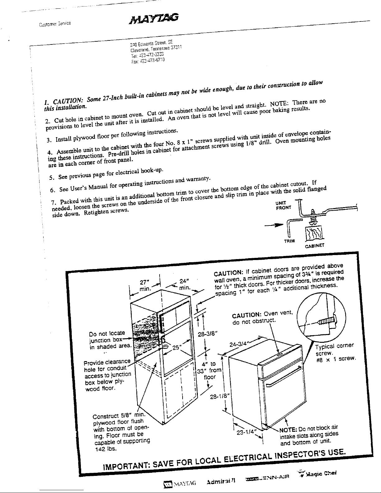
1. CAUTION: Some 27-Inch built-in cabinets may not be wide enough, due to their construction to allow
this installation.
2. Cut hole in cabinet to mount oven. Cut out in cabinet should be level and straight. NOTE: Them are no
provisions to level the unit after it is installed. An oven that is not level will cause poor baking results.
3. Install plywood floor per following instructions.
4. Assemble unit to the cabinet with the four No, 8 x 1" screws supplied with unit inside of envelope contain-
ing these instructions. Pra-dril! holes in cabinet for attachment screws using 1/8" drill, Oven mounting boles
are in each corner of front panel.
5. See previous page for electrical hook-up.
6. See User's Manual for operating instructions and warranty.
7. Packed with this unit is an additional bottom trim to cover the bottom edge of the cabinet cutout, If
needed, loosen the screws on the underside of the front closure and slip trim in place with the solid flanged
side down. Retighten screws.
TRIM J_
CAtqN_r
j •
27" 24" CAUTION: If cabinet doors are provided above
wall oven, a minimum spacing of 3_',t"is required
rain. _ rain. for V=" thick doors. For thicker doors,increasethe
Y 1" for each %" additional thickness.
CAUTION: Oven vent.
0o not locate do not obstruct.
junction box,'--_ 2g-3/8"
in shaded area. |
Provide clearance k,,'E Typical corner
ho(e for conduit"" " ".,_j 4" to screw.
accessto junction "
33" #8 x 1 screw.
box below ply- (-
wood floor. I floor
] 28-1/8"
Construct Sie" r, n.'_ .._
plywood floor flush \
with bottom of open-
ing. Floor must be
cagabie ofsupporting 23. ,NOTE: Do notb)ock air
142 Ibs. _ intake slotsalongsides
/
and bottom of unit.
IMPORTANT: SAVE FOR LOCAL ELECTRICAL INSPECTOR'S USE.
 Loading...