

Page 1
For Future Reference
Write down the model and serial numbers
The model and serial numbers can be found
on the side of the cabinet near the control
panel. Use these numbers in any correspon-
dence or service calls concerning your air
conditioner.
Para referencia futura
Escriba los numeros del modelo y de la serie
Puede encontrar los nfimeros de modelo y de serie en el
costado de la rejilla del frente decorativo cerca del panel
de control. Use estos nfimeros en cualquier corresponden-
cia o llamada de servicio con relaci6n a su acondicionador
de aire.
Room Air Conditioners for
Double-Hung Windows
Acondicionadores de aire
ambientales pare ventanas
de guillotina
Climatiseur d' air indil'iduel
pour fenOtres _ guillotine
Pour r6f6rence ult6rieure
Inscrivez les numeros de modele et de serie
Les num6ros de module et de s_rie se trouvent sur le c6t_ de
la grille dbcorative avant, pros du panneau de commande.
Utilisez ces num_ros lors de toute correspondance ou appel
au service apres-vente ayant trait/_ votre climatiseur.
Model No.. Modelo No.. N °de modOle
Serial No., Nllmero de serie, N ° de s&'k
l)ate of'Purchase, Fecha de la compra, Date d_what
@
@@@@@@@@@@@@@@@@@@@@@@@@@@@@@@@@@@@@@@@@@@@@@@@@@@@@@
@
@
@
@
@
@
@
@
@
@
@
For additional questions please call:
1-866-MAYTAG- 1
or e-maih
customerservice@maytagair, com
@
@
@
@
@
@
@
Keep
these instructions for future reference
Page 2
Important Safety Instructions ooooooooooooooooooooooo
Electrical Shock Hazard
1. Plug unit only into grounded electrical outlet,
2. Do not use an extension cord or plug adapter with this unit,
3. Do not operate unit with front removed,
Failure to follow the above precautions could result in electrical
shock, fire or personal injury.
If the air conditioner has a serial plate rating of 11S volts and greater
than 7.5 amps it must have its own fuse or circuit breaker, and no
other device or unit should be operated on that fuse or circuit breaker.
If the air conditioner has a serial plate rating of 230 volts it must
have its own fuse or circuit breaker, and no other device or unit
should be operated on that fuse or circuit breaker.
The location of the serial plate that applies to this inodel can be
found on the back page of this manual.
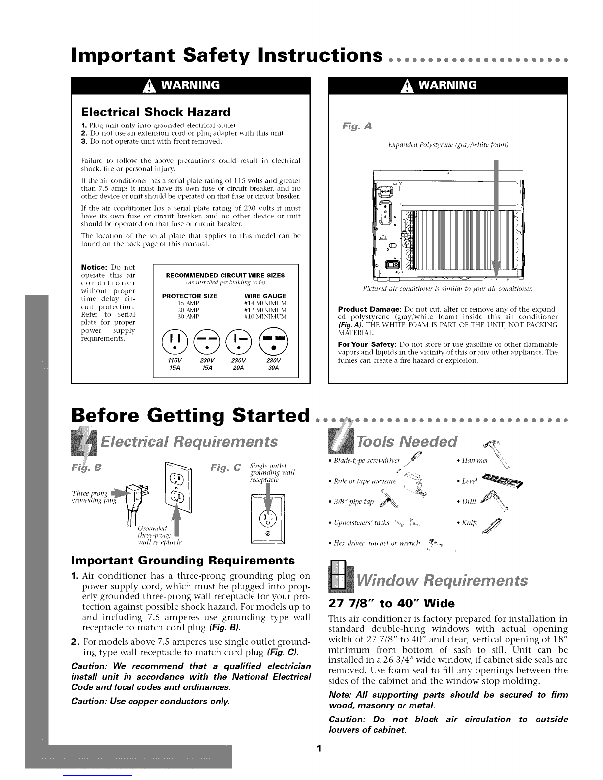
Hgo A
Expanded Polystyrene (gray/white tbam)
Notice: Do not
operate this air
conditioner
without proper
time delay cir-
cuit protection.
Refer to serial
plate for proper
power supply
requireInents.
RECOMMENDED CIRCUIT WIRE SIZES
(As hlstalled per blfildi_l,¢ co&)
PROTECTOR SIZE WIRE GAUGE
1S AMP #14 MINIMUM
20 AMP #12 MINIMUM
30 AMP # 10 MINIMUM
@©©@
115V 230V 230V 230V
15.4 15.4 20A 30A
Pictured air
Product Damage: Do not cut, alter or remove any of the expand-
ed polystyrene (gray/white foam) inside this air conditioner
(Fig. AL THE WHITE FOAM IS PART OF THE UNIT, NOT PACKING
MATERIAL,
For Your Safety: Do not store or use gasoline or other flaInmable
vapors and liquids in the vicinity of this or any other appliance. The
fumes can create a fire hazard or explosion.
conditioner is similar to your air conditioner:
Before Getting Started °°° °°°°°°°°°°°°°°°°°°°°°°°°°o
Electrical Requ[yements
_o _ Single outlet
_#rolmdin_#wall
• Upholsterers' tacks "_ j _-_ • Knifi" A ,/
• Hex driver) ratchet or wrench _,_
j
c_
Important Grounding Requirements
1. Air conditioner has a three-prong grounding plug on
power supply cord, which must be plugged into prop-
erly grounded three-prong wall receptacle for your pro-
tection against possible shock hazard. For models up to
and including 7.5 amperes use grounding type wall
receptacle to match cord plug (Fig. B).
2. For models above 7.5 amperes use single outlet ground-
ing type wall receptacle to match cord plug (Fig. C).
Caution: We recommend that a qualified electrician
install unit in accordance with the National Electrical
Code and local codes and ordinances.
Caution: Use copper conductors only.
Window Requ[rements
27 718" to 40" Wide
This air conditioner is factory prepared for installation in
standard double-hung windows with actual opening
width of 27 7/8" to 40" and clear, vertical opening of 18"
minimum from bottom of sash to sill. Unit can be
installed in a 26 3/4" wide window, if cabinet side seals are
removed. Use foam seal to fill any openings between the
sides of the cabinet and the window stop molding.
Note: All supporting parts should be secured to firm
wood, masonry or metal
Caution: Do not block air circulation to outside
louvers of cabinet.
Page 3
Installation°°°°°°°°°°°°°°°°°°°°°°°°°°°°°°°°°°°°°°°°°°°°°°°°
Decoraffve & ChassT RemovM
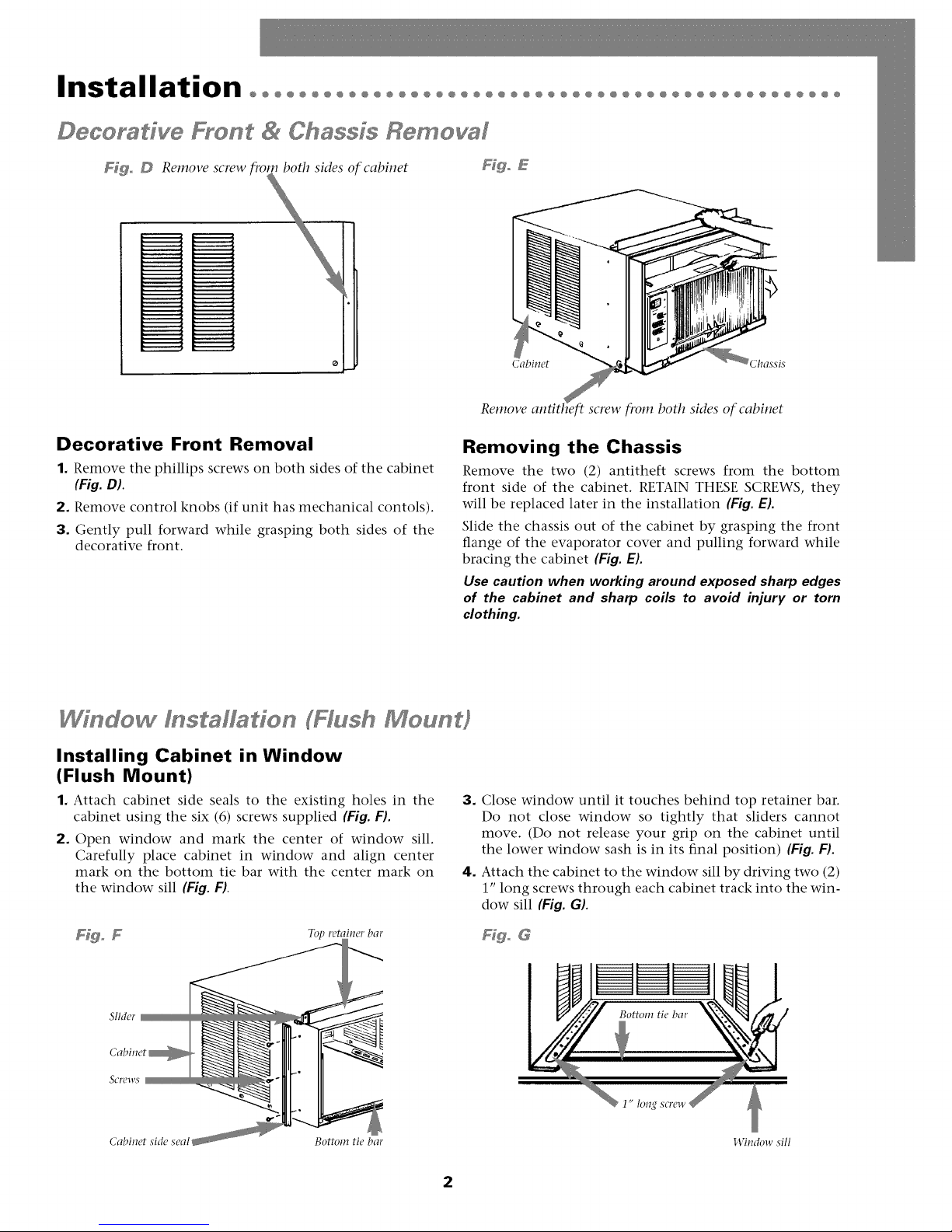
Ffgo D Rernove screw fivrn both sides of cabinet Ffgo E
Cabinet Chassis
Decorative Front Removal
1. Remove the phillips screws on both sides of the cabinet
(Fig. D).
2. Remove control knobs (if unit has mechanical contols).
3. Gently pull forward while grasping both sides of the
decorative front.
Window f staffaffon (Hash Moun#
Installing Cabinet in Window
(Flush Mount)
1. Attach cabinet side seals to the existing holes in the
cabinet using the six (6) screws supplied (Fig. F).
2. Open window and mark the center of window sill.
Carefully place cabinet in window and align center
mark on the bottom tie bar with the center mark on
the window sill (Fig. F).
Rel,17ove
screw f!_om both sides of cabinet
Removing the Chassis
Remove the two (2) antitheft screws from the bottom
front side of the cabinet. RETAIN THESE SCREWS, they
will be replaced later in the installation (Fig. E).
Slide the chassis out of the cabinet by grasping the front
flange of the evaporator cover and pulling forward while
bracing the cabinet (Fig. E).
Use caution when working around exposed sharp edges
of the cabinet and sharp coils to avoid injury or torn
clothing.
3. Close window until it touches behind top retainer bar.
Do not close window so tightly that sliders cannot
move. (Do not release your grip on the cabinet until
the lower window sash is in its final position) (Fig. F).
4. Attach the cabinet to the window sill by driving two (2)
1" long screws through each cabinet track into the win-
dow sill (Fig. G).
Slider
Cabinet
SCI'OWS
Cabinet side seal Bottom tie bar
Ffgo G
1" long
145mlow sill
2
Page 4
Installation°°°°°°°°°°°°°°°°°°°°°°°°°°°°°°°°°°°°°°°°°°°°°°°°°°°°
Wi dew l staHade FHush Meu t)
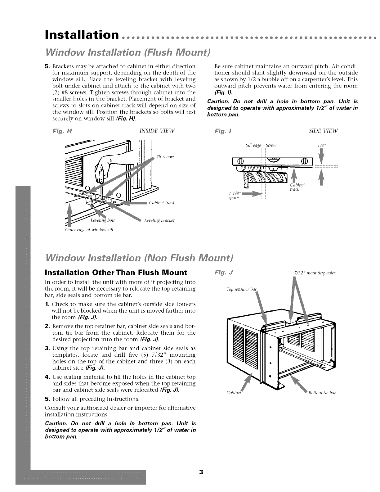
5. Brackets may be attached to cabinet in either direction
for maximum support, depending on the depth of the
window sill. Place the leveling bracket with leveling
bolt under cabinet and attach to the cabinet with two
(2) #8 screws. Tighten screws through cabinet into the
smaller holes in the bracket. Placement of bracket and
screws to slots on cabinet track will depend on size of
the window sill. Position the brackets so bolts will rest
securely on window sill (Fig. H).
Be sure cabinet maintains an outward pitch. Air condi-
tioner should slant slightly downward on the outside
as shown by 1/2 a bubble off on a carpenter's level. This
outward pitch prevents water from entering the room
(Fig. I).
Caution: Do not drill a hole in bottom pan. Unit is
designed to operate with approximately 1/2" of water in
bottom pan.
F@o N INSIDE VIEW Fdgo 5 SIDE VIEW
Sill e_qe Screw
Outer edge of window sill
bolt
#8 SCI'CWS
Cabinet track
Leveli1_q bracket
1 1/4"_
SpaCC
® .........
Cabinet
Ira&
I/4"
Wfndow dnstaHadon (Non Hush Moun }
Installation OtherThan Flush Mount
In order to install the unit with more of it projecting into
the room, it will be necessary to relocate the top retaining
bar, side seals and bottom tie bar.
1. Check to make sure the cabinet's outside side louvers
will not be blocked when the unit is moved farther into
the room (Fig. d).
2. Remove the top retainer bar, cabinet side seals and bot-
tom tie bar from the cabinet. Relocate them for the
desired projection into the room (Fig. d).
3. Using the top retaining bar and cabinet side seals as
templates, locate and drill five (S) 7/32" mounting
holes on the top of the cabinet and three (3) on each
cabinet side (Fig. J).
4. Use sealing material to fill the holes in the cabinet top
and sides that become exposed when the top retaining
bar and cabinet side seals were relocated (Fig. J).
5. Follow all preceding instructions.
Consult your authorized dealer or importer for alternative
installation instructions.
Caution: Do not drill a hole in bottom pan. Unit is
designed to operate with approximately 1/2" of water in
bottom pan.
Fdgo d
7/32" mounting boles
T(Q retainerbar
Bottom tie bar
3
Page 5
@@@@@@@@@@@@@@@@@@@@@@@@@@@@@@@@@@@@@@@@@@@@@@@@@@@@@@@@@@@@@@@@@@@
Ffffer P3 el I s Mf3ffo
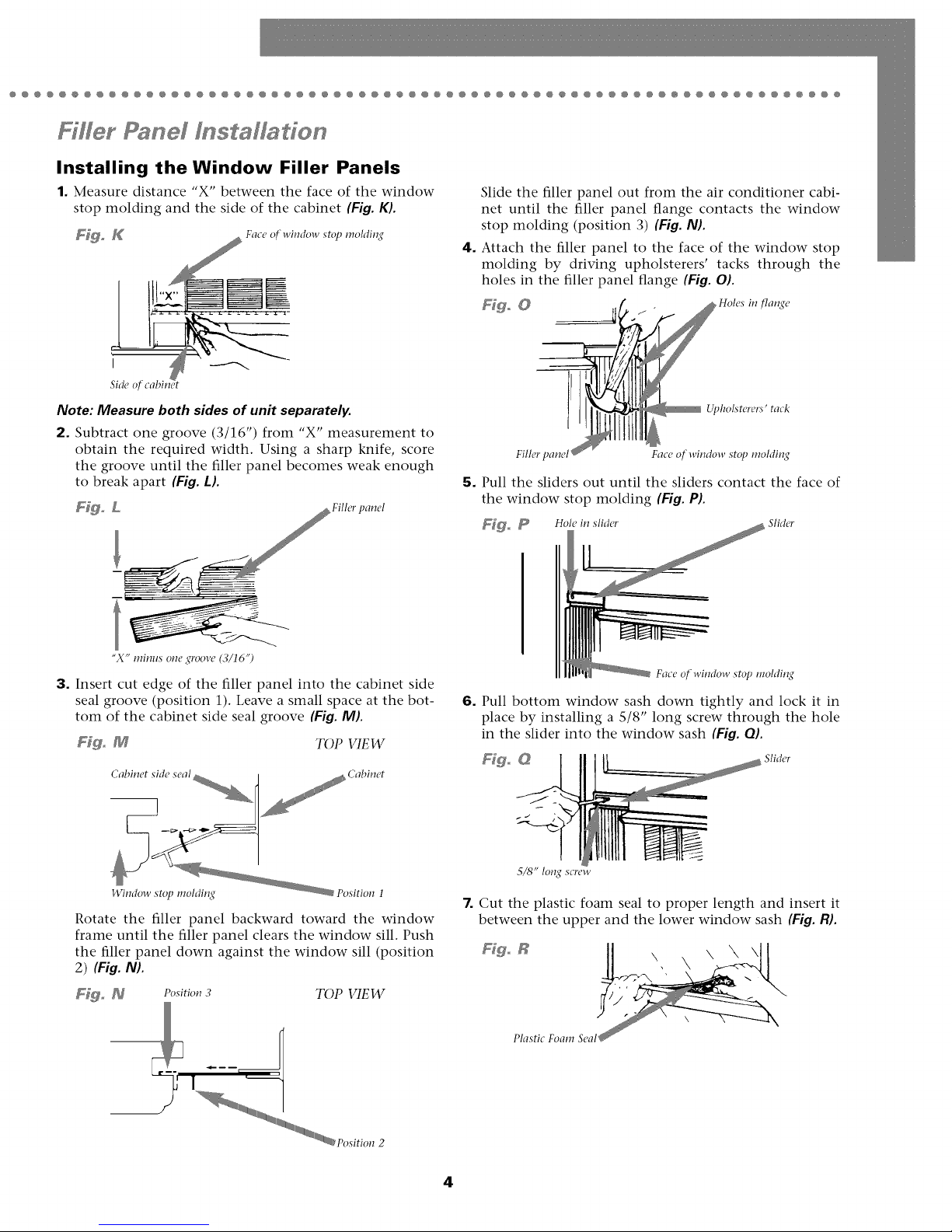
Installing the Window Filler Panels
1. Measure distance "X" between the face of the window
stop molding and the side of the cabinet (Fig. K).
F_ K Face o[ window stop molding
Side of cabindt
Note: Measure both sides of unit separately.
2. Subtract one groove (3/16") from "X" measurement to
obtain the required width, Using a sharp knife, score
the groove until the filler panel becomes weak enough
to break apart (Fig. L).
F_o L Filh, rpanel
4. Attach the filler panel to the face of the window stop
5. Pull the sliders out until the sliders contact the face of
Slide the filler panel out from the air conditioner cabi-
net until the filler panel flange contacts the window
stop molding (position 3) (Fig. NL
molding by driving upholsterers' tacks through the
holes in the filler panel flange (Fig. OL
Fills,r pane1711111111lil lll_Face of-window stop rooMing
the window stop molding (Fig. P).
F_o _ Hole in slider Slider
"X" minus one 2¢roove(3/16")
3. Insert cut edge of the filler panel into the cabinet side
seal groove (position 1). Leave a small space at the bot-
tom of the cabinet side seal groove (Fig. M).
F_go M TOP VIEW
145udow stop molding€
Rotate the filler panel backward toward the window
frame until the filler panel clears the window sill. Push
the filler panel down against the window sill (position
2) (Fig. N).
F_. _ Position 3 TOP VIEW
v_
my"
Face of window stop rooMing
6. Pull bottom window sash down tightly and lock it in
place by installing a 5/8" long screw through the hole
in the slider into the window sash (Fig. OL
Figo @ Slid(..
5/8" long screw
7. Cut the plastic foam seal to proper length and insert it
between the upper and the lower window sash (Fig. R).
F_go R
Plastic Foam Seal
\\\
\
4
Page 6
Installation°°°°°°°°°°°°°°°°°°°°°°°°°°°°°°°°°°°°°°°°°°°°°°°°°°°°
Chassfs f s affado
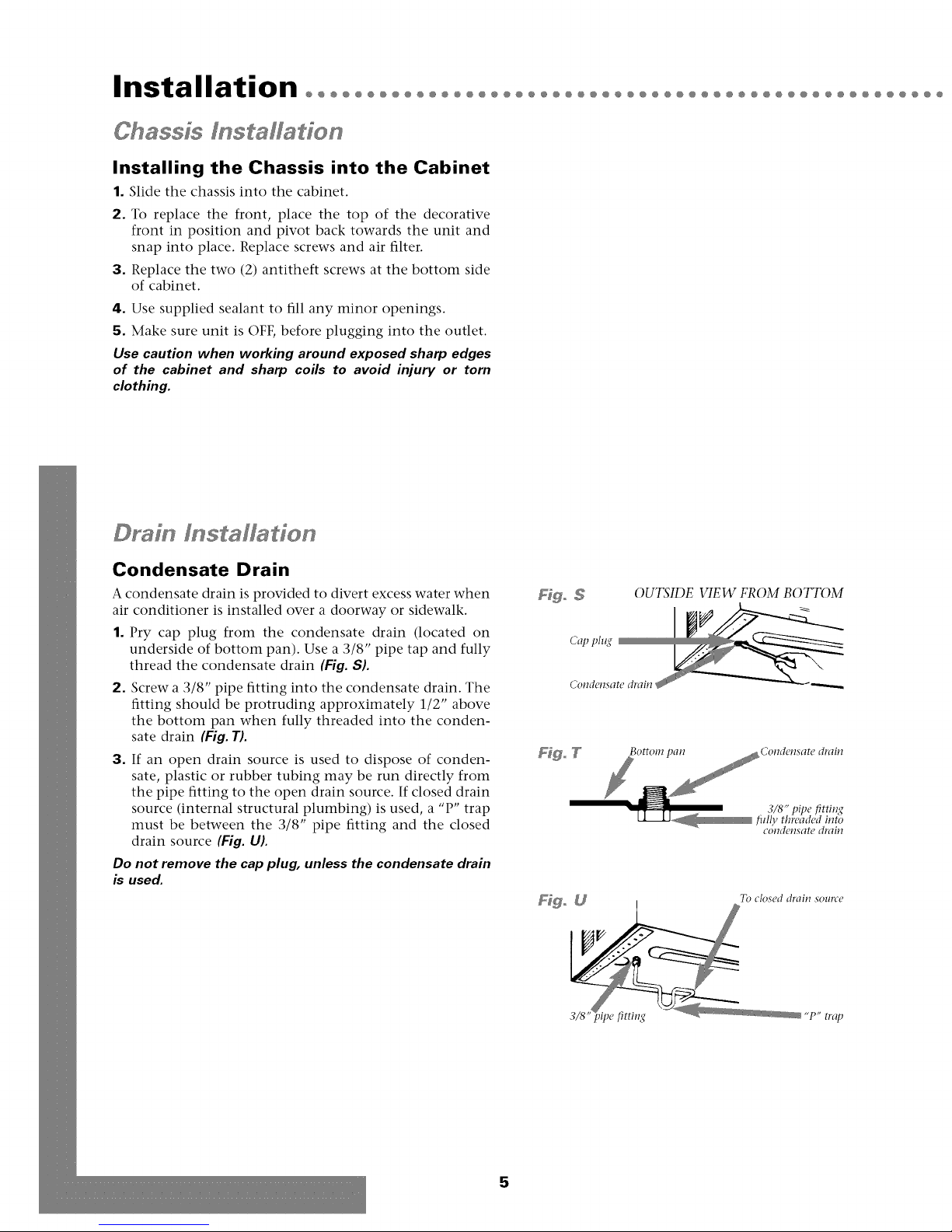
Installing the Chassis into the Cabinet
1. Slide the chassis into the cabinet.
2. To replace the front, place the top of the decorative
front in position and pivot back towards the unit and
snap into place. Replace screws and air filter.
3. Replace the two (2) antitheft screws at the bottom side
of cabinet.
4. Use supplied sealant to fill any minor openings.
5. Make sure unit is OFF, before plugging into the outlet.
Use caution when working around exposed sharp edges
of the cabinet and sharp coils to avoid injury or torn
clothing.
Drafn Instalfadon
Condensate Drain
A condensate drain is provided to divert excess water when
air conditioner is installed over a doorway or sidewalk.
1. Pry cap plug from the condensate drain (located on
underside of bottom pan). Use a 3/8" pipe tap and fully
thread the condensate drain (Fig. S).
2. Screw a 3/8" pipe fitting into the condensate drain. The
fitting should be protruding approximately 1/2" above
the bottom pan when fully threaded into the conden-
sate drain (Fig. T).
3. If an open drain source is used to dispose of conden-
sate, plastic or rubber tubing may be run directly from
the pipe fitting to the open drain source. If closed drain
source (internal structural plumbing) is used, a "P" trap
must be between the 3/8" pipe fitting and the closed
drain source (Fig. U).
Do not remove the cap plug, unless the condensate drain
is used.
OUTSIDE VIEW FROM BOTTOM
_o [J To closed drain source
P ,,p. trat)
5
Page 7
@@@@@@@@@@@@@@@@@@@@@@@@@@@@@@@@@@@@@@@@@@@@@@@@@@@@@@@@@@@@@@@@@@@
T rougho heoWaff I s affado
This air conditioner is designed as a slide-out type chassis,
making it possible to install it through-the-wall in both exist-
ing and new construction. We recommend that this type of
installation be performed with professional assistance.
IMPORTANT: This appliance must be installed according to
all applicable electrical and building codes and ordinances.
It is recommended that you have help to install your unit
and that you use proper lifting technique to avoid per-
sonal injury.
It is important that you inspect the condition of the wall
where the air conditioner will be installed. Be sure the wall
can support the weight of the unit.
All cabinet louvers MUST BE on the outdoor side of the
wall. DO NOT BLOCK SIDE LOUVERS.
The cabinet must be installed level from side-to-side and
with a downward tilt from inside to outside.
DO NOT USE AN EXTENSION CORD: Make certain a
proper electrically sized wall receptacle is available close to
the unit. If not, make arrangements to install one.
If the air conditioner has a serial plate rating of 115 volts
and greater than 7.5 amps it must have its own fuse or cir-
cuit breaker, and no other device or unit should be oper-
ated on that fuse or circuit breaker.
If the air conditioner has a serial plate rating of 230 volts it
must have its own fuse or circuit breaker, and no other device
or unit should be operated on that fuse or circuit breaker.
1. First remove the Decorative front panel and chassis
from the cabinet. Remove top and side retainer bars
from the cabinet (see page 2).
2. Determine the size of the opening for a wood frame by
adding 1/8" to the width and height of the cabinet.
Measure height from top of cabinet to bottom of bar.
Add this measurement to the thickness of wood used to
build the frame. This will determine the size of wall
opening needed. Minimum 1" thick lumber is recom-
mended when building the frame. When determining
finish frame thickness, be sure not to cover side louvers
on the cabinet.
3. Install the finished frame in the wall opening square
and level, nail or screw it securely to the wall and place
the cabinet into the framed wall opening.
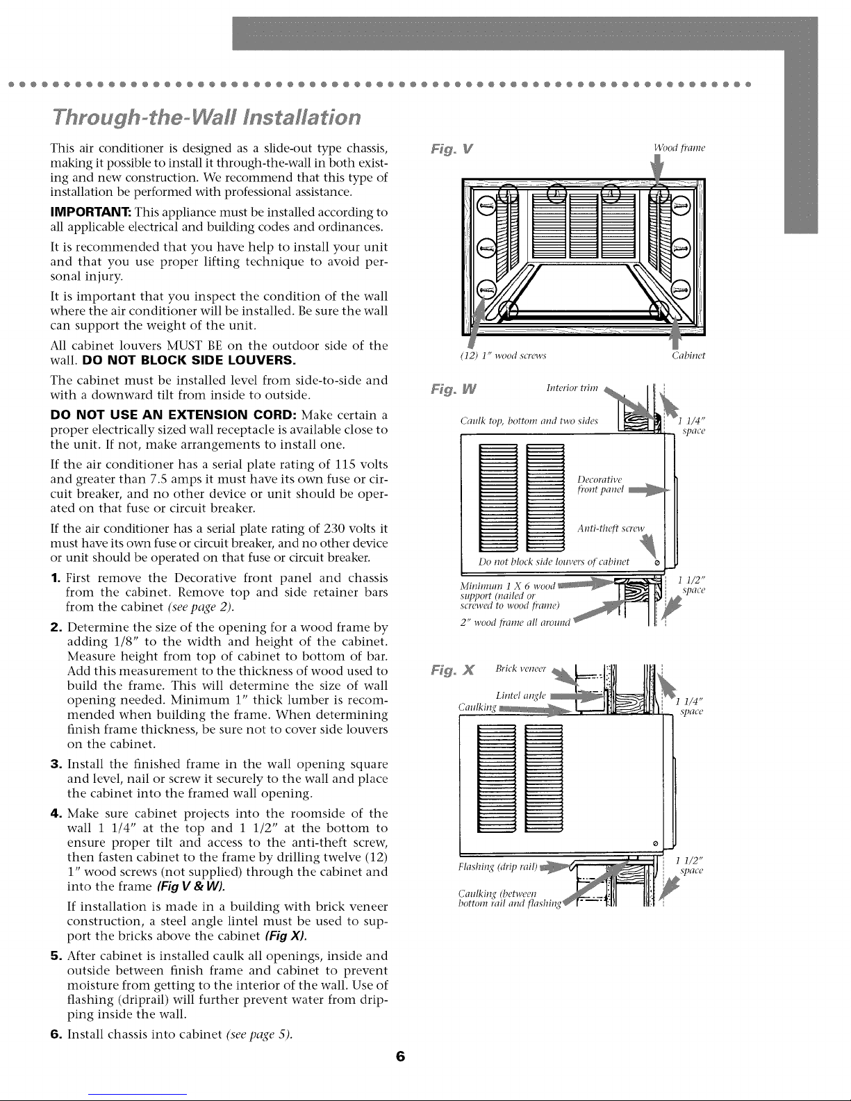
4. Make sure cabinet projects into the roomside of the
wall 1 1/4" at the top and 1 1/2" at the bottom to
ensure proper tilt and access to the anti-theft screw,
then fasten cabinet to the frame by drilling twelve (12)
1" wood screws (not supplied) through the cabinet and
into the frame (Fig V & W).
If installation is made in a building with brick veneer
construction, a steel angle lintel must be used to sup-
port the bricks above the cabinet (Fig XL
5. After cabinet is installed caulk all openings, inside and
outside between finish frame and cabinet to prevent
moisture from getting to the interior of the wall. Use of
flashing (driprail) will further prevent water from drip-
ping inside the wall.
6. Install chassis into cabinet (see page 5).
6
(12) 1" wood screws
Fd_ _ Interior trim
Caulk top, bottom and two sides
Ddcorativc
fi'ont panel _
Anti-theft screw
Do not block sMe louvers of cabinet
Minimum 1
support (nailed or
screwed to wood fi'ame)
2" wood fi'ame all around
Flashin
Caulkin,¢ (bel-weeu
bottom rail and flashing
Cabinet
1/2"
S]D_TCd
1/2"
SpfICC
Page 8
Operation°°°°°°°°°°°°°°°°°°°°°°°°°°°°°°°°°°°°°°°°°°°°°°°°°°
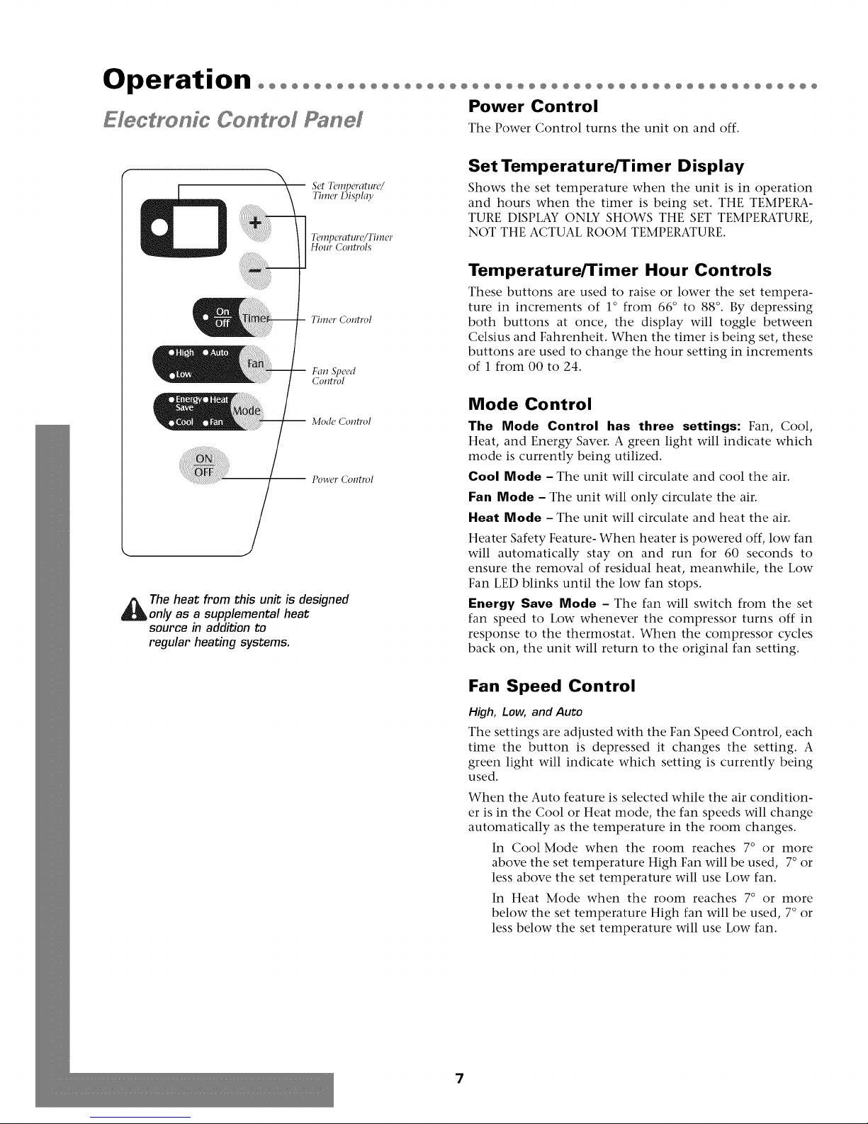
Power Control
E_eC_rO_fC CO_rO_ Pa_e_ Tile Power Control turns tile unit on and off.
Set Temperature/Timer Display
Set Temperature/
Timer Distflay
Temperatm'e/Timer
Hour Controls
TIIllCI' Colltrol
Fan Speed
Control
Mode Control
-- Power Control
_ he heat from this unit is designed
only as a supplemental heat
source in addition to
regular heating systems.
Shows the set temperature when the unit is in operation
and hours when the timer is being set. THE TEMPERA-
TURE DISPLAY ONLY SHOWS THE SET TEMPERATURE,
NOT THE ACTUAL ROOM TEMPERATURE.
Temperature/Timer Hour Controls
These buttons are used to raise or lower the set tempera-
ture in increments of 1° from 66 ° to 88 °. By depressing
both buttons at once, the display will toggle between
Celsius and Fahrenheit. When the timer is being set, these
buttons are used to change the hour setting in increments
of 1 from 00 to 24.
Mode Control
The Mode Control has three settings: Fan, Cool,
Heat, and Energy Saver. A green light will indicate which
mode is currently being utilized.
Cool Mode - The unit will circulate and cool the air.
Fan Mode - The unit will only circulate the air.
Heat Mode - The unit will circulate and heat the air.
Heater Safety Feature- When heater is powered off, low fan
will automatically stay on and run for 60 seconds to
ensure the removal of residual heat, meanwhile, the Low
Fan LED blinks until the low fan stops.
I=nergy Save Mode - The fan will switch from the set
fan speed to Low whenever the compressor turns off in
response to the thermostat. When the compressor cycles
back on, the unit will return to the original fan setting.
Fan Speed Control
High, Low, and Auto
The settings are adjusted with the Fan Speed Control, each
time the button is depressed it changes the setting. A
green light will indicate which setting is currently being
used.
When the Auto feature is selected while the air condition-
er is in the Cool or Heat mode, the fan speeds will change
automatically as the temperature in the room changes.
In Cool Mode when the room reaches 7 ° or more
above the set temperature High Fan will be used, 7° or
less above the set temperature will use Low fan.
In Heat Mode when the room reaches 7° or more
below the set temperature High fan will be used, 7 ° or
less below the set temperature will use Low fan.
7
Page 9

@@@@@@@@@@@@@@@@@@@@@@@@@@@@@@@@@@@@@@@@@@@@@@@@@@@@@@@@@@@@@@@
Timer Control
The timer can be set to either turn the unit on or off.
Tile pictured control panel is similar to your panel
@
Set Temperature/
Timer i)isph_y
Temperature/Timer
Hour Controls
Fan Speed
Control
-- Mode ContTvl
To turn the unit ON using theTimer:
• Depress the timer key when the power is off, the
display will read 00. Adjust to the desired number of hours
before TURN ON using the up/down arrows.
• The display will show the time by hours left
until TURN ON.
• To turn the timer off, depress the timer key.
• A green light next to the Timer Control indicates that the
timer is set.
To turn the unit OFF using theTimer.
• Depress the timer key when the power is on, the display will
read 00. Adjust to the desired number of hours before TURN
OFF using the up/down arrows. The display will automatical-
ly go back to the set temperature after 10 seconds.
• To display the amount of time left until TURN OFF, depress
the timer button once.
• To turn the TIMER OFF, depress the timer button twice.
• A green light next to the Timer Control indicates that the
timer is set.
Built-in three minute timing delay.
This electronic controlled unit will not automatically resume
operation after a power failure.
ff this electric unit will not respond to touch pad or remote
control commands, it is necessary to unplug the unit from
the electrical outlet for five seconds and then plug the unit
back in.
Air Conditioner Remote Control
The functions work the same as your air conditioner's touch controls.
Batteries: Remove the cover on the back of the remote controller and insert the batteries with the
(+) and (-) poles pointing in the proper direction.
CAUTION:
• Use only AAA or IEC R03 1.5V batteries.
• Remove the batteries if the remote controller is not used for a
month or longer.
• Do not attempt to recharge the supplied batteries
• All batteries should be replaced at the same time.
• Do not dispose of the batteries in a fire as they may explode.
• Do not mix old and new batteries.
Adjustable louvers
Fdgo d
• Do not install the batteries with the polarity (+/-) reversed.
• Keep batteries and other things that could be swallowed
away from young children. Contact a doctor immediately if
an object is swallowed.
P3 el
Directing Airflow
(Unit with adjustable louvers)
Unit is engineered with adjustable louvers to direct discharge
airflow. Louvers are manually adjusted by moving levers in
direction of desired airflow (Fig. J).
8
Page 10
Maintenance°°°°°°°°°°°°°°°
0000000000000000000000000000000
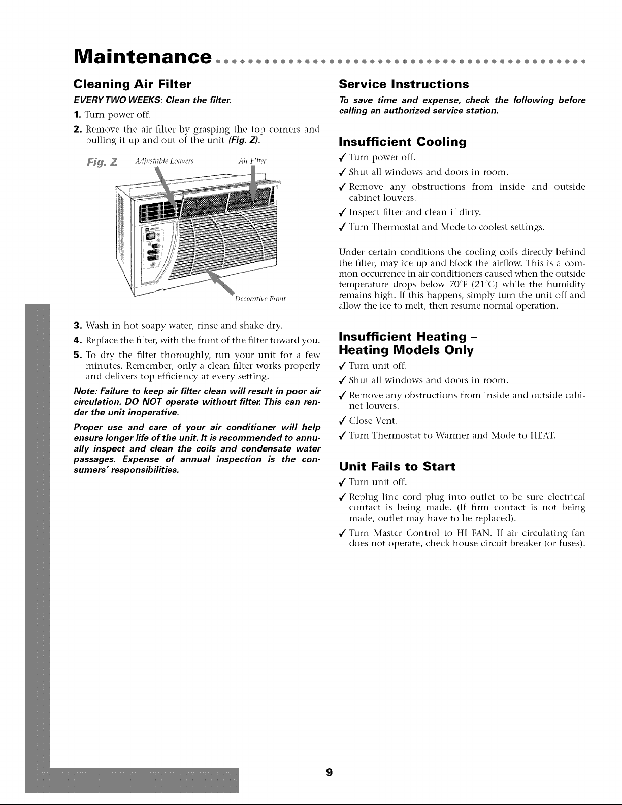
Cleaning Air Filter
EVERY TWO WEEKS: Clean the filter.
1. Turn power off.
2. Remove the air filter by grasping the top corners and
pulling it up and out of the unit (Fig. Z).
F_ Z Adjustabh' Louvers Air Filter
Decorative Front
3. Wash in hot soapy water, rinse and shake dry.
4. Replace the filter, with the front of the filter toward you.
5. To dry the filter thoroughly, run your unit for a few
minutes. Remember, only a clean filter works properly
and delivers top efficiency at every setting.
Note: Failure to keep air filter clean will result in poor air
circulation. DO NOT operate without filter. This can ren-
der the unit inoperative.
Proper use and care of your air conditioner will help
ensure longer life of the unit. It is recommended to annu-
ally inspect and clean the coils and condensate water
passages. Expense of annual inspection is the con-
sumers" responsibilities.
Service Instructions
To save time and expense, check the following before
calling an authorized service station.
Insufficient Cooling
V"Turn power off.
V"Shut all windows and doors in room.
V"Remove any obstructions from inside and
cabinet louvers.
V"Inspect filter and clean if dirty.
V"Turn Thermostat and Mode to coolest settings.
Under certain conditions the cooling coils directly behind
the filter, may ice up and block the airflow. This is a com-
mon occurrence in air conditioners caused when the outside
temperature drops below 70°F (21°C) while the humidity
remains high. If this happens, simply turn the unit off and
allow the ice to melt, then resume normal operation.
outside
Insufficient Heating -
Heating Models Only
V"Turn unit off.
V"Shut all windows and doors in room.
V"Remove any obstructions from inside and outside cabi-
net louvers.
1" Close Vent.
1" Turn Thermostat to Warmer and Mode to HEAT.
Unit Fails to Start
1" Turn unit off.
1" Replug line cord plug into outlet to be sure electrical
contact is being made. (If firm contact is not being
made, outlet may have to be replaced).
1" Turn Master Control to HI FAN. If air circulating fan
does not operate, check house circuit breaker (or fuses).
9
Page 11

Warrantyoooooooooooooooooooo
O@O@O@O@O@O@O@O@O@O@O@O@O@O@O@O
For Models Installed
in North America - If Service
or Parts are Required
First, make the recommended checks. If it appears that ser-
vice or parts are still required, see your room air condition-
er warranty "How to Obtain Warranty Service or Parts".
For Models Installed
Outside North America
For room air conditioners purchased for use outside North
America, the manufacturer does not extend any warranty
either expressed or implied. Consult your local dealer for
any warranty terms extended by the importer in your
country.
Room Air Conditioner Warranty
(Within the 48 contiguous United States, state of Hawaii,
the District of Columbia, Puerto Rico and Canada)
Full (FiveYear) Parts and Labor Warranty
During the five years after the date of original purchase,
Fedders North America will, through its authorized ser-
vicers and free of charge to the owner or any subsequent
user, repair or replace any parts which are defective in
material or workmanship due to normal use. Ready access
to the air conditioner is the responsibility of the owner.
Note: In the event of any required parts replacement with-
in the period of this warranty, Fedders North America
replacement parts shall be used and will be warranted
only for the period remaining on the original warranty.
Exceptions
The above warranty does not cover failure to function
caused by damage to the unit while in your possession
(other than damage caused by defect or malfunction), or
by its improper installation, or by unreasonable use of the
unit, including without limitation, failure to provide rea-
sonable and necessary maintenance or to follow the writ-
ten Installation and Operating Instructions. If the unit is
put to commercial, business, rental, or other use or appli-
cation other than for consumer use, we make no war-
ranties, express or implied, including but not limited to,
any implied warranty of merchantability or fitness for par-
ticular use or purpose.
THE REMEDIES PROVIDED FOR IN THE ABOVE EXPRESS
WARRANTY ARE THE SOLE AND EXCLUSIVE REMEDIES
THEREFOR, NO OTHER EXPRESS WARRANTIES ARE
MADE. ALL IMPLIED WARRANTIES, INCLUDING BUT NOT
LIMITED TO ANY IMPLIED WARRANTY OF MER-
CHANTABILITY OR FITNESS FOR A PARTICULAR USE OR
PURPOSE, ARE LIMITED IN DURATION TO FIVE YEARS
FROM THE DATE OF ORI(;INAL PURCHASE. IN NO EVENT
SHALL FEDDERS NORTH AMERICA BE LIABLE FOR INDI-
RECT, INCIDENTAL, OR CONSEQUENTIAL DAMAGES,
EVEN IF ADVISED IN ADVANCE OF THE POSSIBILITY OF
SUCH DAMAGES. NO WARRANTIES, EXPRESS OR
IMPLIED, ARE MADE TO ANY BUYER UPON RESALE.
Some states do not allow limitations on how long an
implied warranty lasts or do not allow the exclusion or
limitation of incidental or consequential damages, so the
above limitations or exclusions may not apply to you.
This warranty gives you specific legal rights, and you may
also have other rights which may vary from state to state.
No warranties are made for units sold outside of the above
stated areas. Your distributor or final seller may provide a
warranty on units sold outside of these areas.
How to Obtain
Warranty Service or Parts
Service for your room air conditioner will be provided by
CareCo, a division of the manufacturer with authorized
independent CareCo servicers nationwide.
Note: Before calling for service, carefully read the
Installation and Operating Instructions booklet. Then if
you need service:
1. Call a CareCo authorized servicer and advise them of
model number, serial number, date of purchase and
nature of complaint. Service will be provided during
normal working hours. Contact your dealer for the
name of an authorized servicer if unknown to you.
2. If your dealer is unable to give you the name of a ser-
vicer or if you need other assistance, call the following
toll-free number for the name of an authorized servicer
or authorized parts distributor:
1-866-MAYTAG 1
or you may write:
CareCo, Service Department
415 W. Wabash Ave., RO. Box 200
Effingham, IL 62401
Proof of Purchase Date
It is the responsibility of the consumer to establish the
original purchase date for warranty purposes. We recom-
mend that a bill of sale, cancelled check, or some other
appropriate payment record be kept for that purpose.
10
Page 12

Instrucciones importantes de seguridadoooooooooo
Peligro de descarga el6ctrica
1. Enchufe la unidad en till tonlacorriente con conexi(m a tierra.
2. No use un cable de extensi6n ni un adaptador de enchufe con este
aparato,
3. No 1o haga funcionar sin la cubierta delantera.
El no seguir las precauciones enumeradas anteriornmnte podria
causar descargas el0ctricas, incendio o lesiones personales,
Si el acondicionador de aim trae en la placa una clasificaci6n de 11S
voltios y ross de 7.S amperios, entonces debe ir conectado a su pro-
pio fusible o cortacircuitos y ningfm otro aparato o unidad se podr5
conectar a dicho fusible o cortacircuitos,
Si el acondicionador de aire trae en la placa una clasificaci6n de 230
voltios, entonces deber_ ir conectado a su propio fusible o cortacir-
cuitos y ningfin otro aparato o unidad se podr_ conectar a dicho
fusible o cortacircuitos.
La ubicaci6n de la placa en 0ste modelo se encuentra indicada en la
filtima p,_gina de Oste manual,
Aviso: No haga
funcionar estre
aire acondi-
cionado sin un
circuito tempo-
rizador que
brinde la protec-
cidn adecuada.
En la placa de
identificaci6n
aparecen los req-
uisitos correctos
de alilnentaci6n,
TAIVIAI_IOS RECOMENDADOS PARA LOS
ALAMBRES DEL CIRCUITO
(I*>stalados('ggm los n'glame*_tos de co*_strI*dci&_)
TAMAI_O DEL CALIBRE DEL
PROTECTOR ALAMBRE
15 AMP #14 MINIM°
20 AMP #12 MINIMO
O) AMP #10 MINIMO
@©©@
115V 230V 230V 230V
16A 16A 20A 30A
E_go A
Poliestireno ey[)andido (Es])llllltl _{ris/blanca)
El aire acomiicionado de 1¢1fi_to es similar ¢11szlyo.
Dafio al producto: No corte, altere o retire ningdI1 pedazo de poli-
estireno expandido (espuma gris/blanca) que se encuentre dentro del
acondicionador de aim (Fig. AL EL POLIESTIRENO EXPANDIDO
FORMA PARTE DE LAUNIDAD, NO ES MATERIAL DE EMBALAJE,
Para su seguridad: No ahnacene ni utilice gasolina u otros vapores
y liquidos inflamables cerca de este artefacto o de cualquier otro arte-
facto, Los vapores pueden provocar un incendio o una explosi6n,
Antes de empezaroooooooooo ooooooooooooooooooooooooooo
Heryam[entaa neceaadaa
• Martillo
• Nivel
• Taladro _
• Cuchill(i J
de tmesta a tierra
Requistos importantes
para la conexi6n a tierra
1. E1 equipo de aire acondicionado tiene en el cord6n de
corriente un enchufe a tierra de tres puntas, el cual debe
set introducido en un tomacorriente de tres puntas
debidamente conectado a tierra para protecci6n contra
posibles descargas el_ctricos. Para modelos de hasta 7.5
amperios utilice un tipo de tomacorriente con conexi6n
a tierra, adecuado para el enchufe del equipo (Fig. B).
2. Para modelos de mils de 7.S amperios, utilice un tomacor-
riente con conexi6n a tierra para un solo enchufe (Fig.¢).
Precaucion: Recomendamos que un electricista calificado
instale la unidad de acuerdo alas normas electicas
nacionales y las normas y regulaciones locales.
Precaucion: Utilice solamente conductores de cobre.
• Destornillador comdn /
• R<2¢lao cinta m(,trica '_Z
• Conexi6n de tubo de 3/8 de/ml X
• Tachuelas para tapicer& _ _-_
• DestornilladoT; llave o matraca hexagonales !_...
/
Requ[sYtoa de fa ventana
27 7/8 a 40 pulgadas
E1acondicionador de aire se prepara en la f_brica para una
instalaci6n est_ndar en ventanas de guillotina con una
abertura a lo ancho de 27 7/8 a 40 pulgadas de ancho y 18
pulgadas de altura minima desde el bastidor inferior hasta
el quicio de la ventana. La unidad puede instalarse en una
ventana de 26 3/4 pulgadas de ancho, si se retiran los sel-
ladores laterales del gabinete. Utilice sellador de espuma
de goma para llenar las aberturas entre los lados del gabi-
nete y la moldura de tope de la ventana.
Nota: Todaslas piezas de apoyo deberan asegurarse a
madera, material de albafiileria o metal firme.
Precaucion:No bloquee la circulaciondel aire de las rejil-
las exteriores del gabinete.
11
Page 13

Instalaci6n oooooooooooooooooooooooooooooooooooooooooooooooo
Q
Para retirar el frente decorativo
1. Retire los tornillos que se encuentran a ambos lados
del gabinete (Fig. D).
2. Quite las dos perillas de control (control mecfinico
solamente).
3. Tire suavemente hacia adelante mientras sostiene
los dos lados del frente decorativo.
C6mo instalar el gabinete
en la ventana (montaje a ras)
1. Fije los sellos lateral del gabinete a los agujeros exis-
tentes en el gabinete usando los seis (6) tornillos sum-
inistrados (Fig. F).
2. Abrir la ventana y marcar el centro del quicio de la ven-
tana. Colocar cuidadosamente el gabinete en la ventana
y alinear la marca del centro en la barra separadora con
la marca del centro del quicio de la ventana (Fig. F).
Gabinete
Retire los tornillo de ambos lados del gabinete
Chasis
C6mo retirar el chasis
Quitar los dos tornillos, localizados en el fondo y frente de
la careta. GUARDE ESTOS TORNILLOS, ellos deberfin set
colocados de nuevo en la instalaci6n (Fig. E).
Corra el chasis hacia afuera sujetando el frente de la
cubierta del evaporador y halando hacia delante mientras
se apoya en el gabinete (Fig. E).
Tenga cuidado cuando este trabajando alrededor de las
esquinas afiladas del gabinete para evitar heridas o ropas
rasgadas.
3. Cerrar la ventana hasta que toque la parte de atrfis de la
barra de retencidn superior. No cerrar la ventana tan
apretadamente que no se puedan mover las deslizado-
ras. (No soltar el gabinete hasta que el bastidor inferior
de la ventana est_ en su posicidn final) (Fig. F).
4. Monte el gabinete al antepecho de ventana con dos (2)
tornillos de una pulgada insertados a trav6s de cada car-
ril del gabinete asegurfindolos dentro del antepecho de
ventana (Fig. G).
F_o _ Barra tle retemri61tsuperior
Deslizadora
Gabinete
Tornillos
Sello lateral del2(abinete
%Tonullo & zlna/
OJlicio de a venrtana
12
Page 14

Instalaci6n oooooooooooooooooooooooooooooooooooooooooooooooo
5. Se puede acoplar los soportes al gabinete en cualquier
direcci6n para lograr un mfiximo apoyo, dependiendo
de la profundidad de la repisa de la ventana. Coloque
el soporte nivelador con el perno nivelador debajo del
gabinete y ac6plelos al gabinete con dos (2) tornillos
#8. Apriete los tornillos a trav_s de los orificios mils
pequehos en el soporte. La colocaci6n del soporte y los
tornillos en el riel del gabinete dependerfi del tamaho
de la repisa de la ventana. Coloque los soportes de tal
Cerci6rese de que el gabinete mantenga una incli-
naci6n hacia afuera. E1 acondicionador de aire deberfi
inclinarse ligeramente hacia el exterior usando la indi-
caci6n de un nivel de carpintero. Dicha inclinaci6n evi-
tarfi que el agua entre en la habitaci6n (Fig. I).
Precaucidn: No perfore un orificio en la bandeja inferior.
El dise_o de la unidad permite que funcione con aproxi-
madamente 1/2 pulgada de agua en la bandeja inferior.
manera que los pernos niveladores se apoyen firme-
mente en la repisa de la ventana (Fig. H).
Ffgo N VISTA INTERIOR Ffgo 5 VISTA LATERAL
Borde de Tornillo
la repisa
Tornillos
#8
Bol'dC ¢xtcl'ior d(" Ja l'('pisa de! la v(,lltal'la
®1
Rid del
,gabinete
i/4 _
Instalaci6n diferente al montaje a ras
Para instalar la unidad de modo que se proyecte en la
habitaci6n, serfi necesario reubicar la barra de retenci6n
superior, los selladores laterales, y la barra de separaci6n
inferior.
1. Verifique que las rejillas laterales de la parte exterior del
gabinete no queden bloqueadas al colocar la unidad en
la habitaci6n (Fig. J).
2. Retire del gabinete la barra de retenci6n superior, los
selladores laterales del gabinete y la barra separadora
inferior. Reubiquelos hastaencontrar la proyecci6n
deseada dentro de la habitaci6n (Fig. J).
3. Utilizando la barra de retenci6n superior y los sell-
adores laterales del gabinete como plantillas, ubique y
perfore cinco (S) oriflcios de montaje de 7/32 pulgada
en la parte superior del gabinete y tres (3) en cada costa-
do del gabinete (Fig. J).
4. Utilice material de sellar para llenar los orificios de la
parte superior y de los lados del gabinete que quedaron
expuestos cuando se reubicaron la barra de retenci6n
superior y los selladores laterales del gabinete (Fig. J).
5. Siga las instrucciones precedentes.
Consulte al distribuidor o importador autorizado en caso
de necesitar instrucciones para instalaciones alternativas.
Ffgo J Orificios de montajo de 7/32"
Gabinete Barra
Precaucion: No perfore un orificio en la bandeja inferior.
El dise_o de la unidad permite que funcione con aproxi-
madamente 1/2 pulgada de agua en la bandeja inferior.
13
Page 15

@@@@@@@@@@@@@@@@@@@@@@@@@@@@@@@@@@@@@@@@@@@@@@@@@@@@@@@@@@@@@@@
C6mo instalar los paneles
de lienado en la ventana
1. Medir la distancia "X" entre la cara de la moldura de
tope de la ventana y el lado del gabinete (Fig. KL
_ _ Cara de la mohhn'a de tope
Lado del ,_abhwte
Nora: IVledirambos lados de la unidad per separado°
2. Reste una muesca (3/16") de la medici6n "X" para
obtener el ancho necesario. Utilizando un cuchillo aft-
lado, raspe la muesca hasta que el panel de llenado se
debilite lo suficiente para desprenderlo (Fig. I-L
F_ L Panel de relleno
de la ventana
Deslizar el panel de relleno sacfindolo del gabinete del
acondicionador de aire hasta que el reborde del panel
de relleno haga contacto con la moldura de tope de la
ventana (posici6n 3) (Fig. N).
Unir el panel de relleno a la cara de la moldura de tope
de la ventana clavando tachuelas de tapicero en los ori-
ficios del reborde del panel de relleno (Fig OL
Figo 0 _ _ °riOci(':l'_rff"
5. Sacar las deslizadoras hasta que hagan contacto con la
cara de la moldura de tope de la ventana (Fig.PL
_o _ Orificio en deslizadora Deslizadora
"X" menos um_ ranura (3/16 pulgada)
a. Insertar el borde cortado del panel de relleno en la
ranura de sellar del costado del gabinete (posici6n 1).
Dejar un peque_o espacio en la base de la ranura de sel-
lar del costado del gabinete (Fig. M).
F_go M VISTA SUPERIOR
Mohlm'a de tope tle la ventana
Rotar el panel de relleno hacia atrfis en el marco de la
ventana hasta que el quicio de la ventana quede despe-
jado. Empujar el panel de relleno hacia abajo contra el
alf4izar de la ventana (posicidn 2) (Fig. N).
F_go N I'osici6,3 VISTA SUPERIOR
Cara de la moldura de tope de
6. Tirar hacia abajo el bastidor inferior de la ventana y tra-
barlo en su lugar instalando un tornillo de 5/8 pulgada
de largo por el orificio de la deslizadora en el bastidor
de la ventana (Fig. QL
Tornillo de 5/8 pulgada de lat_o
7. Corte el largo correcto del sellador de espuma de plfisti-
co e ins4rtelo entre el bastidor de ventana superior e
inferior (Fig. R).
Hgo
\ \
Sellador de estmma de pldstico
\\\
v_
Posicifn 2 14
Page 16

Instalaci6n oooooooooooooooooooooooooooooooooooooooooooooooo
Instafadon de1 chasfs
C6mo instalar el chasis en el gabinete
1. Corra el chasis hacia dentro del gabinete.
2. Para reemplazar el frente, coloque la parte superior del
panel decorativo en posicidn y gire hacia atrfis en direc-
cidn a la unidad y coloque en sitio. Reemplace los
tornillos y el filtro de aire.
3. Vuelva a colocar los dos (2) tornillos en el rondo del
gabinete.
4. Usar el sellador provddo para llenar pequehas aberturas.
5. Asegfirese que la unidad estfi en OFF, osea desconecta-
da, antes de conectar la unidad a la corriente.
Tenga cuidado cuando este trabajando alrededor de las
esquinas afiladas del gabinete para evitar heridas o ropas
rasgadas.
Instafadon de1 drena]e
Drenaje de condensaci6n
Se proporciona un drenaje de condensaciOn para desviar
el agua excesiva cuando el acondicionador de aire se insta-
la sobre una puerta o acera.
1. Separar el tapdn del drenaje de condensacidn (ubicado
en la parte inferior de la bandeja). Utilizar un conector
de tubo de 3/8" y enroscar completamente el drenaje de
condensacidn (Fig. S).
2. Atornillar un ajuste de tubo de 3/8" en el drenaje de
condensacidn. E1 ajuste deberfi sobresalir aproximada-
mente 1/2" sobre la bandeja inferior cuando estO com-
pletamente enroscado en el drenaje de condensacidn
(Fig. T).
3. Si se utiliza una fuente de drenaje abierta para eliminar
el producto de la condensaciOn, podrfi hacerse pasar un
tubo de plfistico o de goma directamente desde el ajuste
de tubo hasta la fuente de drenaje abierta. Si se utiliza
una fuente de drenaje cerrada (tuberia estructural inter-
na), deberfi haber una trampa "P" entre el ajuste de
tubo de 3/8" y la fuente de drenaje cerrada (Fig. U).
No quitar el tapon a menos que se use el drenaje de
condensado.
F goS
Tapdn
Drenalede
COlldCl2Stlci(_tl
F_go T
_o [J Hacia filente tle drenaje
VISTA EXTERIOR DESDE ABAJO
Bandeja infbrior Drem@de
CoIld_!IIS_tCiOtl
Ajuste de mbo de
3/8" completamente
enmscada en el
drena]e de
conddnsacidn
!2 . Trampa "F"
15
Page 17

@@@@@@@@@@@@@@@@@@@@@@@@@@@@@@@@@@@@@@@@@@@@@@@@@@@@@@@@@@@@@@@
Este aparato de aire acondicionado estfi disefiado con un
chasis deslizante, lo cual hace posible instalarlo a tray,s de
la pared en edificaciones existentes o en construcciones
nuevas. Recomendamos que este tipo de instalaci6n lo
realice con ayuda profesional.
IMPORTANTE: Este electrodom_stico debe instalarse de
conformidad con todas las ordenanzas y c6digos el4ctricos
y de construcci6n aplicables.
Se recomienda obtener ayuda para instalar su unidad y
que el instalador aplique thcnicas apropiadas para el alza-
do de objetos pesados a fin de evitar lesiones personales.
Es importante inspeccionar la condici6n de la pared
donde se instalarfi el aire acondicionado. Aseghrese de que
la pared tenga capacidad suficiente para soportar el peso
de la unidad.
_ _ Mohlura interior
Todas las ventilas del gabinete deben quedar colocadas en
el lado exterior de la Eared. NO BLOQUEE LAS REJIL-
LAS DE VENTILAClON LATERALES O VENTILAS.
E1 gabinete debe instalarse a nivel horizontalmente de
lado a lado y con una inclinaci6n del frente hacia atrfis
(del interior al exterior).
NO USE EXTENSlONES ELECTRICAS: Aseg0rese de que
haya disponible un tomacorrientes con capacidad apropiada
cerca de la unidad. De lo contrario, instale uno nuevo.
Si la placa del fabricante del aparato de aire acondiciona-
do indica un voltaje nominal de 11S voltios y una corri-
ente mayor de 7,S amperios, serfi necesario instalarlo con
su propio fusible o interruptor automfitico (disyuntor), y
no deberfi conectarse ningfin otro aparato el4ctrico a
dicho fusible o interruptor el4ctrico.
Si la placa del fabricante del aparato de aire acondiciona-
do indica un voltaje nominal de 230 voltios serfi necesario
_o ,_ Revestimient
instalarlo con su propio fusible o interruptor automfitico
(disyuntor), y no deberfi conectarse ningfin otro aparato
el4ctrico a dicho fusible o interruptor el4ctrico.
1. Primero retire el panel frontal decorativo y el chasis del
gabinete. Retire las barras de sujeci6n superior y lat-
erales del gabinete (vdase la p_gina 12).
2. Determine el tamafio de la abertura para el marco de
madera, afiadiendo 1/8" a la anchura y a la altura del
gabinete. Mida la altura desde la parte superior del gabi-
nete hasta la parte inferior de la barra. Afiada esta medi-
das al grosor de la madera utilizada para construir el
marco. Esto determinarfi el tamafio necesario de la
abertura en la pared. Se recomienda usar madera con
un grosor minimo de 1" para construir el marco. A1
determinar el grosor final del marco, asegOrese de no
cubrir las ventilas laterales en el gabinete.
3. Instale el marco de acabado en la abertura de la pared,
y asegOrese de 4ste quede a escuadra y a nivel, clfivelo o
atornillelo para fijarlo a la pared e introduzca el gabi-
nete en la abertura enmarcada en la pared.
4. Aseghrese de que el gabinete se proyecte sobre la super-
ficie de la pared en el interior de la habitaci6n, 1 1/4" de
pulgada en la parte superior y 1 1/2" en la parte inferi-
or, para lograr una inclinaci6n apropiada y acceso al
tornillo de seguridad (antirrobo), a continuaci6n fije el
gabinete al marco, con ayuda de un taladro enrosque
doce (12) tornillos de 1" para madera (no suministra-
dos) a trav4s del gabinete hasta el marco (Fig. V y IN).
Si se realiza la instalaci6n en un edificio construido con
revestimiento de ladrillo, serfi necesario instalar un din-
tel de fingulo de acero para apoyar los ladrillos sobre el
gabinete (Fig. X).
5. Despu4s de instalar el gabinete calafatee todas las aber-
turas por dentro y por fuera entre el marco de acabado
y el gabinete para evitar que la humedad penetre al
interior de la pared. Instale un cubrejuntas (corta gotas)
para evitar que el agua penetre por goteo al interior de
la pared.
6. Instale el chasis en el gabinete (vdase la p_ina 15).
16
(12) tor1#llos de 1" para madera
Calafatee la parte superior;
la parte inferior y los hides
Panel
dccol'atll/O
fi'ontal
Tor1_illo de
sequridad
No bloquee las ventilas laterales del gabinete e
Apoyo de madera de
1 .v 6" colllo tHflliIHo (clavado 0
atomillado al de madera
M¢11'C0 dc tH¢tdcI'¢t
Dintel de dl_(ulo
Sello de cala
(riel cortagotas)
Calafhteado (entre el riel
inferior y el cubrejtmtas)
(¢f;ztirrobo) %
Gabinete
I 1/4"
Proyec-
ci6n de
i 1/2"
cidh de
' 1/4"
Provec-
ci6n de
1/2"
Page 18

FuncionamientOoooooooooooooooooooooooooooooooooooooooooo
Control de Alimentaci6n
Panel de control elec ydnfco
Pantalla de
c(mf_g.racifn de
tempera_lra/reloj
Controle,s de
tPIHpcl'atlll'a/hol'aS
dereloj
Control de relo]
Control tle
velocidad tle
ve,tilador
i Control
de modo
i Control tle
El calor proveniente de este
acondicionador de aire ha sido
disefiado solamente como una
fuente de calor suplementario
y no sustituye a los sistemas
de calefaccibn regulares.
alimentaci6n
Este bot6n pone en marcha y apaga el acondicionador de aire.
Indicador de Temperatura de Ajuste/Temporizador
E1indicador muestra la temperatura de ajuste cuando el acondi-
cionador de aire est_ en funcionamiento y las horas cuando se ha
activado el temporizador. EL INDICADOR DE LATEMPERATURA
SOLAMENTE MUESTRA LA TEMPERATURA DE AJUSTE, NO LA
TEMPERATURAAMBIENTE REAL.
Control de laTemperatura/Temporizador
Estos botones se usan para aumentar o reducir la temperatura de
ajuste en incrementos de 1°, entre 66°F hasta 88°E Si se oprimen
simult_neamente ambos botones, el indicador digital cambiar_
entre grados Celsius y Fahrenheit. Cuando se activa el tempo-
rizador, estos botones son usados para cambiar el ajuste de la hora
en incrementos de 1, entre 00 hasta 24.
Selector de Modo
Una luz verde indicar_ el modo que est_ siendo utilizado.
Mode "Cool" {Frio) - E1 acondicionador de aire circula y enfria
el aire.
Mode "Heat" (Calor) - E1 acondicionador de aire circula y
calienta el aire.
Caracteristica de Seguridad del Calentador - Cuando el calenta-
dot est_ apagado, el ventilador de baja velocidad se activar_ y
funcionar_ durante 60 segundos para asegurar la eliminaci6n de
algfin calor residual, a la vez que el diodo LED 'Low Fan' (venti-
lador de baja velocidad) destella hasta que se detenga el venti-
lador de baja velocidad.
Mode 'Fan" (Ventilador) - E1 acondicionador de aire solamente
har_ circular el aire.
Mode 'Energy Save" (Ahorro de Energia) -
(El modo de ahorro de energia est_ disef]ado para funcionar sola-
mente con el modo 'Cool'). E1ventilador cambiar_ de la veloci-
dad de ajuste a velocidad baja cuando el compresor sea apagado
por el termostato. Cuando el compresor se activa nuevamente, el
ventilador volver_ al ajuste original. La velocidad del ventilador
cambia autom_ticamente segfin cambie la temperatura en la
habitaci6n.
Control de la Velocidad del Ventilador-
Alta, Baja y Automdtica
E1ajuste de la velocidad del ventilador se cambia cada vez que se
oprime el bot6n de control de velocidad del ventilador. Una luz
verde indicar_ el ajuste que se ha seleccionado.
Cuando se selecciona 'Auto' (Autom_tico) y el acondicionador de
aire est_ en el modo 'Cool' o 'Heat', la velocidad del ventilador
cambiar_ autom_ticamente a medida que cambie la temperatura
en la habitaci6n. En el modo 'Cool', cuando la habitaci6n llega
a 7° o m_s, sobre la temperatura de ajuste, se usa 'High Fan' (Alta
Velocidad), cuando la temperatura en la habitaci6n es de 7° o
menos, sobre la temperatura de ajuste, se usa 'Low Fan'
(Velocidad Baja). En el modo 'Heat' cuando la habitaci6n alcan-
za 7° o m_s, bajo la temperatura de ajuste, se usa 'High Fan',
cuando la habitaci6n alcance 7° o menos, bajo la temperatura de
ajuste, se usa 'Low Fan'.
17
Page 19

@@@@@@@@@@@@@@@@@@@@@@@@@@@@@@@@@@@@@@@@@@@@@@@@@@@@@@@@@@@@@@@
Pane# de contro# e#ectrdn#co
Control del Ternporizador (Eltemporizador puede ser ajustado ya sea para encender o apagar el acondicionador de aire.)
Para PONER EN MARCHA automfiticamente el acondi- Para APAGAR automfiticamente el acondicionador de aire
cionador de aire usando el modo 'Timer': usando el modo 'Timer':
1.
Oprima el bot6n 'Timer' cuando la alimentaci6n
el_ctrica est_ desconectada. E1 indicador mostrarfi
00. Ajuste el indicador para que muestre el mimero
de horas que desea que transcurran antes de la
PUESTA EN MARCHA, usando las flechas de ajuste
'Temperature/Timer' (Temperatur a/Temporizador).
2.
E1 indicador mostrarfi la cantidad de horas que fal-
tan para la PUESTA EN MARCHA.
3.
Para salir del modo 'Timer', optima el bot6n 'Timer'.
4.
Una luz verde situada junto al bot6n 'Timer' se ilu-
minarfi para indicar que el 'Timer' estfi activado.
Mecanismo de retraso de tres minutos incorporado.
Este aparato controlado electronicamente reanudara su operacion despues de la interrupcion del ser-
vicio electrico.
Si este aparato electronico no responde a los mandos del control remoto o cojinete tactil, sera
necesario desenchufarlo cinco segundos y luego volver a enchufar.
1. Oprima el botdn 'Timer' cuando la alimentacidn el_ctri-
ca est_ conectada. E1 indicador mostrarfi 00. Ajuste el
indicador para que muestre el mimero de horas que desea
que transcurran antes de que se APAGUE usando las fie-
chas de ajuste 'Temperature/Timer'
(Temperatura/Temporizador). (Despu6s de 10 segundos,
el indicador volverfi automfiticamente a la temperatura
de ajuste.)
2. Para vet la cantidad de horas que faltan para que se
APAGUE el acondicionador de aire, optima una vez el
botdn 'Timer'.
3.
Para salir del modo 'Timer', optima el bot6n 'Timer' dos
veces.
4. Una luz verde situada junto al bot6n 'Timer' se iluminarfi
para indicar que el 'Timer' estfi activado.
Co_tyo# Remoto de Aco_dic#oy_ado_ de A#re
Las funciones trabajan igual que los controles manuales de su acondicionador de aire.
Pilas:
Retire al tapa en la parte trasera del control remoto e inserte las baterias con los polos (+) y (-) en la direcci6n correcta.
• Use solabente pilas AAA o IEC R03 de 1,5V.
• Retire las pilas si el control remoto no va a set usado durante un
mes o m_s.
• No h_tente recargar las pilas suministradas.
• Todas las pilas deben set reemplazadas a un mismo tiempo.
• No incrinere/as pilas pues pueden explotar.
• No instale las pilas con la polaridad (+/-) inversa.
• Mantenga fuera de/alcance de los ni_os peque_os las pilas y otros artfculos que puedan set tragados.
Pdngase h_mediatamente en contacto con un m_dico si un ni_o peque_o se traga un objeto.
18
Page 20

MantenimientOoooooooooooo
@@@@@@@@@@@@@@@@@@@@@@@@@@@@@@@
Limpieza del filtro de aire
CADA DOS SEMAIVAS:Limpie el filtro.
1. Ponga el Control de alimentaci6n en posici6n apagado.
2. Para retirar el filtro de aire, sujhtelo de las esquinas supe-
riores y remu4valo hacia arriba y hacia afuera (Fig. Z).
_ _ Persianas ajustables Filtros &, aire
3. Lfivelo con agua caliente enjabonada, enjufiguelo, sacfi-
dalo y s_quelo.
4. A1 ponerlo de nuevo en su lugar, asegfirese que el lado
frontal quede mirando a usted.
5. Para secar bien el filtro, haga funcionar la unidad
durante unos minutos. Recuerde, que s61o un filtro
limpio harfi funcionar su unidad correctamente y darfi
siempre el servicio mils eficiente.
Advertencia: El no mantener limpio el filtro podria resul-
tar en baja circulacion del aire. NUNCA haga funcionar la
unMad sin el filtro ya que puede quedar inutilizable.
El uso y mantenimiento adecuados del acondicionador
de air prolongara la vMa util de la unMad. Se recomienda
inspeccionar y limpiar anualmente el serpentin y los
pasajes para agua de condensacion. El cliente debera
cubrir los gastos de inspeccion anuaL
Orientaci6n de la
corriente de aire
(Unidad con rejilla directriz ajustable)
La unidad viene equipada con rejillas directrices ajustables
que permiten dirigir la descarga de la corriente de aire. Las
rejillas pueden ajustarse manualmente moviendo las
palancas en la direcci6n deseada (Fig. d).
Servicio
Para ahorrar tiempo y gastos, revise Io siguiente antes de
Ilamar a la empresa de servicio autorizado.
Enfriamiento insuficiente
1" Ponga el Control de alimentaci6n en posici6n apagado.
1" Cierre todas las ventanas y puertas de la habitaci6n.
1" Retire todas las obstrucciones de las rejillas interna
y externa del gabinete de la unidad.
1" Puerta de ventilaci6n (disponible en la mayoria de los
modelos).
1" Inspeccione el filtro y limpielo si estfi sucio.
1" Ponga el termostato y el control maestro en los valores
mils frios.
Bajo ciertas condiciones, los serpentines de enfriamiento
ubicados directamente detrfis del filtro podrian congelarse
y bloquear el pasaje del aire. Esto ocurre por lo general en
acondicionadores de aire cuando la temperatura externa
desciende a menos de 21°C (70°F) mientras que la
humedad se mantiene elevada. Si esto ocurre, simple-
mente apague la unidad y deje que se derrita el hielo antes
de reanudar el funcionamiento normal.
Calefacci6n insuficiente-
Modelos con calefacci6n solamente
1" Ponga el Control de alimentaci6n en posici6n apagado.
1" Cierre todas las ventanas y puertas de la habitaci6n.
1" Retire todas las obstrucciones de las rejillas interna y
externa del gabinete de la unidad.
1" Cierre la ventilaci6n.
Si la unidad no se enciende
1" Ponga el control maestro en posici6n apagado.
1" Vuelva a enchufar el enchufe del cord6n en el tomacor-
riente para cerciorarse de que se estfi haciendo el con-
tacto el_ctrico. (Si no se verifica un contacto firme serfi
necesario cambiar el tomacorriente).
1" Ponga el control de ventilador en alto. Si el ventilador
de circulaci6n de aire no funciona, verifique los disyun-
tores o fusibles de la residencia.
19
Page 21

Garantiaooooooooooooooooooooo
0000000000000000000000000000000
Para modelos instalados en
Norteam6rica - En caso de necesidad
de servicio o piezas
Haga primer() las verificaciones recomendadas. En caso
de necesitarse servicio o piezas, consulte en la garantia de
su acondicionador de aire en la secci6n "C6mo obtener
servicio o piezas de garantia'.
Para modelos instalados
fuera de Norteam_rica
Para aires acondicionados comprados para uso fuera de
Norteam_rica el fabricante no otorgarfi ninguna garantia
implicita o explicita. Consulte a su distribuidor autoriza-
do sobre las condiciones de la garantia extendida pot el
importador de los equipos de su pais.
Garantia del acondicionador de aire
(Dentro de los 48 estados contiguos de los Estados
Unidos, estado de Hawai, Distrito de Columbia, Puerto
Rico y Canada)
Garantia para todas las piezas (cinco a_os)
y mano de obra
A partir de la fecha de compra y durante un periodo de
cinco aflos, Fedders North America, mediante sus esta-
ciones de servicio autorizadas, repararfi o reemplazarfi sin
costo alguno para el propietario o usuario, cualquier pieza
que presente dafios de material o mano de obra derivados
del uso normal del producto. Es responsabilidad del propi-
etario facilitar el acceso al acondicionador de aire para
realizar los servicios de reparaci6n.
Nota: En caso de que se requiera reemplazar una pieza
mientras la garantia esta vigente, se utilizaran los
repuestos de Fedders North America los cuales contin-
uaran en vignecia solamente durante el resto del periodo
de garantia de la unidad.
Excepciones
La garantia antes indicada no cubre las fallas de fun-
cionamiento causadas por daflos que sufra la unidad
mientras _sta est_ en posesi6n del usuario (excluyendo los
daflos causados por defecto o funcionamiento defectu-
oso), o por la instalaci6n incorrecta, o la utilizaci6n inde-
bida de la unidad, incluyendo pero sin limitarse a ello, la
negligencia en proporcionar el mantenimiento necesario
y adecuado o en seguir las "instrucciones de Instalaci6n y
Uso" indicadas por escrito. En caso de utilizarse la unidad
para fines comerciales, de negocios, de arriendo u otto uso
o aplicaci0n que no sea el uso del consumidor, no otorg-
amos garantia explicita ni implicita, incluyendo, pero sin
limitarse a, toda garantia implicita de negociabilidad o
idoneidad para un uso o finalidad particular.
LAS SOLUCIONES EXPUESTAS EN LA GARANTIA ANTERI-
OR SON EXCLUSIVAS. SE RECHAZA CUALQUIER OTRA
GARANTIA YA SEA EXPRESA 0 IMPLICITA, INCLUYENDO,
PERO SIN LIMITARSE A ELL(), TODAS LAS GARANTIAS DE
COMERCIABILIDAD 0 IDONEIDAD PARA UN FIN EN PAR-
TICULAR DURANTE CINCO ANOS A PARTIR DE LA FECHA
DE COMPRA. BAJO NINGUNA CIRCUNSTANCIA FEDDERS
NORTH AMERICA SE HARA RESPONSABLE POR NINGUN
DAI_O DIRECT(), INDIRECT() 0 CONSECUENCIAL, SIN
IMPORTAR LA CAUSA DE LA ACCION, AUN CUANDO
FEDDERS NORTH AMERICA HAYA SIDO ADVERTIDO CON
ANTERIORIDAD DE LA POSIBILIDAD DE DICHOS DAN()&
NO SE OFRECE NINGUNA GARANTIA EXPRESA 0 IMPLICI-
TA A COMPRADORES DESPUES DE LA REVENTA.
Algunos estados no permiten limitar el tiempo de
duraci6n de una garantia implicita ni permiten excluir ni
limitar los daflos incidentales o emergentes, de modo que
las limitaciones o exclusiones antes indicadas podrian no
aplicarse en su caso. Esta garantia le otorga derechos
legales especificos. Usted podria tener tambi_n otros dere-
chos que pueden variar de estado a estado.
No se ofrecen garantias para las unidades vendidas fuera
de las fireas antes indicadas. Su distribuidor o vendedor
final podria proporcionar una garantia para las unidades
vendidas fuera de estas fireas.
C6rno obtener servicio
o piezas de garantia
E1 servicio para su acondicionador de aire serfi provisto por
CareCo, una divisi6n del fabricante con estaciones de ser-
vicio independientes CareCo autorizadas en todo el pais.
Nota: Antes de solicitar servicio, lea cuidadosamente el
folleto de "lnstrucciones de Instalacion y Uso" Luego, si
necesita servicio:
1. Llame a un taller de servicio autorizado CareCo y
suministreles el nfimero de modelo, nfimero de serie, la
fecha de compra y la naturaleza del problema. E1 servicio
se prestarfi durante horas normales de trabajo.
Comuniquese con su distribuidor para obtener recomen-
daciones sobre una estaci6nde servicio autorizada.
2. Si su distribuidor no puede proporcionarle el nombre
de un taller de servicio o si necesita otro tipo de asis-
tencia, llame al siguiente nfimero gratis para obtener el
nombre de un taller de servicio autorizado o dis-
tribuidor de piezas autorizado:
1-866-MAYTAG 1
o escriba al:
Departamente de Servicio de CareCo
415 W. Wabash Ave., RO. Box 200
Effingham, IL 62401 EE. UU.
Prueba de la fecha de compra
E1 establecimiento de la fecha de compra original para
efectos de la garantla es responsabilidad del consumidor.
Recomendamos mantener la factura de compra, el cheque
cancelado o algfin otto registro de pago apropiado para
dicho efecto.
20
Page 22

Directives de s6curit6 importanteSooooooooooooooooo
Danger de choc 6lectrique
1. N'enfieher le dimatiseur que dans une prise _leetrique raise ,5la term.
2. Ne passe servir d'une rallonge ou d'un adaptateur avec cet
appareiL
3. Ne pas faire marcher le climatiseur si le panneau avant a OtOretirO.
Suivre les pr6cautions indiqu6es ci-dessus pour 6viter tout risque
d'Olectrocution, d'incendie ou de 16sion corporelle.
Si la plaque de s6rie du climatiseur indique une tension en volts
noIninale de 11.5 volts et une intensitO en aInpbres nominale
sup6rieure fi 7,5 A, l'appareil dolt _tre dot6 de son propre fusible ou
disjoncteur et aucun autre appareil ne doit y &re branch6.
Si la plaque de s6rie du climatiseur indique une tension en volts
nominale de 230 volts, l'appareil doit Otre dotO de son propre
fusible ou disjoncteur et aucun autre appareil ne doit y &re
branchO.
L'emplacement de la plaque de s6rie de ce Inodble est indiquO au
verso du manuel.
Avis: Ne pas
utiliser le clima-
tiseur sans la
protection d'un
circuit de tem-
porisation. Se
reporter fi la
plaque signal&
tique pour
toute indica-
tion de puis-
sance exigOe,
CALIBRES DE FIL RECOMMANDI_S
(Sdlm l'i_lstallation stilml&
par lecode&"conOrucdon)
PROTECTION CALIBRE
DU CIRCUIT DE FIL
1S ,4 N°14 MINIMUM
20A N°12MINIMUM
O)A N°I0 MINIMUM
@©©@
115V 230V 230V 230V
15.4 15.4 20.4 30.4
Hgo A
Polystyd,ne expans(' (Mousse grise/bhmche)
L'appareil illustr(, est semblable h votre climatiseur
Endommagement du produit: Ne pas couper, altOrer ou retirer le
polystyrene expansO (mousse grise/blanche) se trouvant _ l'intOrieur
du climatiseur (Fig.,4). LE STYROFOAM N'EST PAS UN EMBALLAGE,
IL FAIT PARTIE INTEGRALE DE L'APPAREIL.
Pour votre s_curit_: Ne )as stocker ou utiliser de l'essence ou toute
autre vapeur ou liquide inflaInmable _ proxilnit_ de cet appareil ou
de tout autre. Les Omanations peuvent crOer un risque d'incendie ou
d'explosion.
Pr6paratifSoooooooooooooooooooooooooooooooooooooooooooooo
OutHs necessaries
• Mal'teall
• Niveall
• Taraud pore' tuyaux de 3/8 po • Perceuse ._
• Broquettes de tapissier _ ii_. • Couteau
Importantes exigences de mise _ la terre
1. E1 climatiseur est pourvu d'une fiche de mise it la terre
trois broches sur le cordon 41ectrique. Cette fiche doit
htre branchhe sur une prise murale 5 trois broches
dfiment raise 5 la terre afin de prothger contre
d'4ventuels risques de chocs. Pour les modules allant
jusqu'au 7.5 A inclusivement, utiliser une prise murale
de type raise _ la terre correspondant 5 la fiche (Fig. B).
2. Pour les modhles de plus de 7.5 A, utiliser une prise
murale simple de raise 5 la terre correspondant 5 la
fiche (Fig. C).
Attention: Nous recommandons que I'appareil soit monte
par un electricien competent conformement au Code elec-
trique national ainsi qu'au code et reglements Iocaux.
Attention: Utiliser uniquement des conducteurs en cuivre.
• Tom'nevis hexagonal, el('h cliquet ou h rochet _i "
Spdefffeado s de fa fe &tre
27 7/8 & 40 po de largeur
Le climatiseur est pr@ar_ fi l'usine en vue d'un montage
dans des fenhtres 5 guillotine standard avec ouverture d'une
largeur effective allant de 27 7/8 5 40 po, et ouverture verti-
cale libre de 18 po mimmum _ partir du has du chfissis de
la fenhtre jusqu'au rebord de la fenhtre. L'appareil peut htre
mont_ dans une fen_tre de 26 3/4 po de largeur, si les joints
sont enlev_s sur les c6t_s du boitier. Utiliser le joint de
mousse pour combler toutes les ouvertures entre les c6t_s
du boitier et la moulure de butte de la fen_tre.
Remarque: Toutes les pieces de soutien doivent _tre
fixees solidement a des surfaces fermes en bois, ma_on-
nerie ou metal.
Mise en garde: Ne pas emp#cher I'air de circuler vers I'ex-
terieur des Iouvres du coffret.
21
Page 23

Montage°°°°°°°°°°°°°°°°°°°°°°°°°°°°°°°°°°°°°°°°°°°°°°°°°°°
du boFde et du pann u ddco adF avan
F_go E
Retirer la vis de C[ltlqlld c6td du boftier
Retirer la vis antivols de chaque c6td du b(fftier
D4pose du panneau frontal d4coratif
1. Retirer les vis de chaque c6t4 du boitier (Fig. D).
2. Retirer les deux boutons de commande (Mod41es
m4canique uniquement).
3. Tirer avec pr4caution vers l'avant tout tenant bien les
deux c6t4s du panneau frontal d4coratif.
Installation du boitier
dans une fen6tre (Montage encastr4)
1. Fixez les joints sur le c6t_ du boitier aux trous existant
dans l'assemblage du boitier 5 l'aide des six (6) vis
fournies (Fig. F).
2. Ouvrir la fenhtre et marquer le centre du rebord de la
fenhtre, Placer soigneusement le boitier dans la fenhtre
et aligner la marque centrale du profil4 de raccorde-
ment inf4rieur sur la marque centrale du rebord de la
fen@re (Fig. F).
Retrait du boitier
Enlevez les deux vis antivols du fond 5 l'avant au c6t4
droit du boitier. CONSERVER CES VIS pour les remettre en
place (Fig. El.
Faire glissez le chSssis _ l'ext4rieur du boRier, en saisissant le
collet de la couverture de protection de l'hvaporateur et en
tirant vers l'avant tout en 4tan_onnant le boitier (Fig. E).
Afin d_vitez des blessures ou des v6tements dechires,
soyez prudent en travaillant autour des serpentins aigus
et les coins tranchants du boitier.
3. Fermer la fen@re jusqu'5 ce qu'elle viennese poser der-
rihre le profil4 de fixation suphrieur. Ne pas fermer la
fen@re si herm@iquement que les glissihres ne peuvent
plus bouger. (Continuer _ tenir le boitier jusqu'5 ce que
la fen@re int4rieure soit en position finale) (Fig. F).
4. Fixer la carrosserie fi la fen@re en enfongant les deux
(2) vis de 1 po de long dans l'appui de la fen@re _ tra-
vers chaque guide de carrosserie. (Fig. G).
Fd_o _ Prof!ld de fixation
Glissi&e
Boftier
Vis
Joint sur le eft(' du
in_rieur
F@o G
Ws de 1
po de lon[_
Rebord de la fi'nStre
22
Page 24

Montage ooooooooooooooooooooooooooooooooooooooooooooooooooo
Installation
5. Les fixations doivent _tre attach6es sur le boitier dans
n'importe quelle direction pour un maximum de sup-
port, selon la profondeur du rebord de la fen_tre. Placez
la fixation de nivellement avec le boulon de nivelle-
ment au-dessous du boRier et attachez le boRier fi l'aide
de deux (2) vis n ° 8. Setter les vis fi travers le boRier dans
les orifices de taille inf6rieure de la fixation. Le place-
ment de la fixations et des boulons de nivellement va
d_pendre de la taille du rebord de la fen_tre. Positionnez
les fixations de fagon fi ce que les boulons reposent de
fagon s_curitaire sur le rebord de la fen_tre (Fig. H).
F_go N VUE INTERIEURE
Rebord extdrieur tle la fenOtre
dana une fendtre (montage encastrd)
Ws n ° 8
Guide de 1 1/4 po
boitiet/ca rrosserie
nivellement Fixation de
nivellentent
S'assurer que le boitier demeure inclinh vers l'ext4rieur.
Le climatiseur dolt pencherl6g_rement fi l'ext4rieur vers
le bas comme indiquh par un dhcalage d'une demi bulle
sur un niveau fi bulle. Cette inclinaison vers l'ext4rieur
empfiche l'eau de p6n_trer dans la piece (Fig. I).
Remarque: Ne pas percer de trou clans la cuvette
inferieure. L'apparei/ est congu de maniere a fonctionner
avec environ 1/2 po d'eau clans le fond de la cuvette.
Ffgo 5 VUE LATERALE
Rebord de fenOtre Vis
1/4po
®
Glfide de
boitiot/
carrossorie
Installation autre qu'un
montage encastr6
Pour poser l'appareil dans des conditions off une plus
grande partie de celui-ci fera saillie dans la piece, il faudra
d@lacer le profil6 de fixation sup_rieur, les joints lat_raux,
et le profil_ de raccordement inf_rieur.
1. S'assurer que les louvres lat6raux ext_rieurs du coffret
ne sont pas bloqu_s lorsque le dispositif est install_ plus
avant dans la piece (Fig. J).
2. Enlever le profil6 de fixation sup_rieur, les joints sur le
c6t4 du boitier, et le profil4 de raccordement inf4rieur
du boitier. D6placer ceux-ci en vue de la saillie d4sir4e
dans la piece (Fig. J).
3. Utilisant comme gabarits le profilh de fixation
sup6rieur et les joints sur le c6th du boitier, situer et
percer cinq (S) trous de montage de 7/32 de po sur le
dessus du boitier et trois (3) de chaque c6t4, du boitier
(Fig. J).
4. Utiliser un agent d'6tanchement pour combler les trous
sur le dessus et les c6ths du boitier qui deviennent
expos6s lorsque le profilh de fixation sup4rieur et les
joints sur le c6t4, du boitier ont 4t6 d4plac4s (Fig. J).
5. Suivre toutes les instructions pr4c4dentes.
Pri6re de consulter un importateur ou vendeur agr44 pour
instructions de montage.
_fgo J Trous de monta,¢e de 7/32 tle po
Prof!ldde fixation
stp&ieur
B&tier de
I'aCCOI'tICIllCHt iHf(_l'lClll '
Attention: Ne pas percer de trou clans la cuvette
inferieure. L'appareil est pourvu d'une evacuation.
L'appareil est congu de maniere a fonctionner avec envi-
ron 1/2 po d'eau dans le fond de la cuvette.
23
Page 25

@@@@@@@@@@@@@@@@@@@@@@@@@@@@@@@@@@@@@@@@@@@@@@@@@@@@@@@@@@@@@@@
|nsta|iation des panneaux
de b|ocage de fen_tre
1. Mesurer la distance "X" entre le devant de la moulure
de butte de la fen[tre et le c6t_ du boitier [Fig, K},
C6t(' d_
Remarque: Mesurer les deux c6t6s de rappareil separ6ment.
2. Soustraire une rainure (3/16") de la mesure _X_>pour
obtenir la largeur d_sir_e. A l'aide d'un couteau tran-
chant, pratiquer une entaille dans la rainure jusqu'a ce
que le panneau de blocage se s_pare facilement (Fig. L).
_ _ Pamleau &' r('mtflissa,¢("
Faire glisser le panneau de remplissage a l'ext_rieur
depuis le boitier du climatiseur jusqu'5 ce que la bride
du panneau de remplissage vienne en contact avec la
moulure de butte de la fen_tre (position 3) (Fig. IV).
Fixer le panneau de remplissage sur le devant de la
moulure de butte de la fen_tre en enfongant des bro-
quettes de tapissier a travers les trous de la bride du
panneau de remplissage {Fig. 0).
F_go 0 Tro.s mms la
i)evant de la tnollhlre de
PanuealJ de renqflissage
but& de la fi'n_tre
bride
tapissier
5. Tirer les glissi_res vers l'ext_rieur jusqu'5 ce qu'elles
viennent en contact avec le devant de la moulure de
butte de la fen_tre (Fig. P}.
_ _ Trou darts la glissg, re Glissig, re
"X" moius mw raimH'e (3/16 tle po)
3. InsUrer le bord coup_ du panneau de remplissage dans
la rainure du joint du c6t_ du boitier (position 1).
Laisser un petit espace au bas de la rainure du joint du
c6t_ du boitier (Fig, M),
F_go M VUE DE DESSUS
MouhH'e de blit('e de la fi'nOtre
Tourner le panneau de remplissage vers l'arri_re en
direction du cadre de la fen_tre jusqu'a ce que le pan-
neau de remplissage se d_gage du rebord de la fen_tre.
Pousser le panneau de remplissage vers le bas contre la
base de la fen_tre (position 2) (Fig. N).
F_go N
Position 3 VUE DE DESSUS
Devant de la mouhH'e de blit(%'
de la fi'n_tre
6. Tirer la fen_tre int_rieure vers le bas fortement et la
bloquer en place en posant une vis de 5/8 po de long
travers le trou de la glissi_re dans la fen_tre int_rieure
(Fig. Q).
Vis de 5/8 po de lon'g
7. Couper le joint en mati_re plastique mousse _ la
longueur appropri_e et l'ins_rer entre la fen_tre
ext4rieure et la fen_tre int_rieure (Fig. RI.
\ \
Joiut eu mati&'e plastique mo1*sse
\\\
24
Page 26

Montage°°°°°°°°°°°°°°°°°°°°°°°°°°°°°°°°°°°°°°°°°°°°°°°°°°°
f s affado de fa eh ss[s
Installation du chassis dans le boitier
1. Glissez le chfissis dans le boRier.
2. Pour reposer le panneau d_coratif, position her le haut
du panneau, faire pivoter le tout vers l'appareil et
enclencher le panneau en place. Reposer les vis et le ill-
tre fi air.
3. Remplacez les deux (2) vis antivols sous le c6t_ du bokier.
f s affado de fa vfda ge
I_vacuation du condensat
Une 6vacuation du condensat est assur_e pour d_verser
l'exc_s d'eau lorsque le climatiseur est mont_ au-dessus
d'un encadrement de porte ou d'un trottoir.
1. A l'aide d'un levier, soulever le bouchon creux de l'6-
vacuation du condensat (situ_e sur le dessous de la
cuvette inf_rieure). Utiliser un taraud pour tuyaux de
3/8 poet tarauder enti_rement l'_vacuation du conden-
sat (Fig. S).
2. Visser un raccord pour tuyaux de 3!8 po dans l'_vacua-
tion du condensat. Le raccord doit faire saillie d'envi-
ron 1/2 po au-dessus de la cuvette inf_rieure lorsqu'il
est viss_ fi fond dans l'_vacuation du condensat (Fig. T).
3. Si une source ouverte d'_vacuation est utilis_e pour la
d_charge du condensat, un tube en plastique ou en
caoutchouc peut relier directement le raccord de tuyau
fi la source ouverte d'_vacuation. Si une source ferrule
d'_vacuation (plomberie structurale interne) est util-
isle, un pi_ge en "P" doit _tre place, entre le raccord
pour tuyaux de 3/8 po et la source ferrule d'_vacuation
(Fig. U).
Ne pas retirer le bouchon creux a moins que la vidange
du condensat soit utilisee.
4. Utiliser le sealant fourni pour boucher toute ouverture
mineure.
5. Soyez certain que l'appareil est fermi, "OFF" avant de
le brancher dans une prise de courant.
afin d_vitez des blessures ou des vOtements dechires,
soyez prudent en travaillant autour des serpentins aigus
et les coins tranchants du boitier.
F_go S VUE EXTERIEUR DEPUIS LE DESSOU8
CI'(qlX
Bouchon V
EVtl{71ltltiOfl dll COHtI('IIstlt
dll co_ldo_ls¢_t
Ffgo U
:Asource farm_;e d'&,aclmtion
25
Rllccol'd t3(llll'
myaux de 3/8 po
Pibse en "P"
Page 27

@@@@@@@@@@@@@@@@@@@@@@@@@@@@@@@@@@@@@@@@@@@@@@@@@@@@@@@@@@@@@@@
E cas ye e f P uys[
Le climatiseur est constitu_ d'un chfissis coulissant, ren-
dant possible son encastrement mural aussi bien dans une
nouvelle construction que dans une construction anci-
enne. Nous recommandons que ce type d'installation soit
effectu_ avec l'assistance d'un professionnel.
IMPORTANT." Cet appareil doit _tre install_ en respectant
tousles codes et ordonnances applicables concernant
l'_lectricit_ et la construction.
Nous vous recommandons de vous faire aider pour
installer cet appareil et d'utiliser les m_thodes de levage
ad_quates pour _viter de w)us blesser.
I1est important d'inspecter lemur off le climatiseur va _tre
encastr_. Assurez-vous notamment que le mur peut sup-
porter le poids de l'appareil.
Toutes les ouvertures d'air du climatiseur DOIVENT se
trouver sur le c6t_ ext_rieur du mur. NE PAS NLOQUER
CES OUVERTURES.
Le climatiseur doit _tre install_ fi niveau sur sa largeur et
l_g_rement inclin_ vers le bas de l'int_rieur vers l'ext_rieur.
NE PAS UTILISER DE RALLONGE IELECTRIQUE:
Assurez-w)us qu'une prise murale d'un calibre ad_quat se
trouve _ proximit_ de l'appareil. Dans le cas contraire, en
faire installer une.
Si le climatiseur comporte une plaque de s_rie indiquant
une tension de 11S volts et une puissance sup_rieure _ 7,S
amperes, l'appareil doit avoir son propre fusible ou dis-
joncteur, et aucun autre appareil ne doit fonctionner sur
ce fusible ou disjoncteur.
Si le climatiseur comporte une plaque de s_rie indiquant
une tension de 230 volts, l'appareil doit avoir son propre
fusible ou disjoncteur, et aucun autre appareil ne doit
fonctionner sur ce fusible ou disjoncteur.
1. Retirer d'abord le panneau d_coratif frontal et le chfissis
du caisson. Retirer les barres de retenue sup_rieure et
lat_rale du caisson (voir page 22 ).
2. D_terminer la taille de l'ouverture de l'encadrement de
bois en ajoutant 1/8 po g la largeur et fi la hauteur du
caisson. Mesurer la hauteur _ partir du haut du caisson
jusqu'au bas de la barre. Ajouter cette mesure g l'@ais-
seur du bois utilis_ pour construire l'encadrement de
bois. Ceci d_terminera la dimension de l'ouverture
murale n_cessaire. I1 est recommand_ d'utiliser du bois
de 1 po d'@aisseur lots de la construction de l'en-
cadrement. Pour d_terminer l'_paisseur de l'en-
cadrement fini, s'assurer de ne pas recouvrir les
ouvertures d'air du caisson.
3. nstaller l'encadrement terming dans l'ouverture carrie
et nivel_, puis utiliser des clous ou des vis pour le fixer
au mur et placer le caisson dans cette ouverture.
4. V_rifier que le caisson s'avance de 1 1/4 po en haut et
de 1 1/2 en bas par rapport au mur int_rieur, afin d'as-
surer une inclinaison adequate et l'acc_s _ la vis
antivol. Fixer le caisson _ l'encadrement de bois en
enfongant douze (12) vis fi bois de 1 po (non fournies)
travers le caisson et l'encadrement (Fig. Vet W).
Si l'installation se fait dans un mur avec placage de
briques, un linteau de corni_re en acier doit _tre utilis_
pour supporter les briques au-dessus du caisson (Fig. X).
_ _ Bmd i_m_'rie_r
5. Une fois le caisson installS, calfeutrer tousles interstices
int_rieurs et ext_rieurs entre l'encadrement fini et le
caisson pour emp_cher l'humidit_ de p_n_trer _ l'in-
t_rieur du mur. L'utilisation d'un solin (d'une goutti_re)
peut mieux aider _ pr_venir la p_n_tration de l'eau
dans lemur.
6. Installer le chfissis dans le caisson (voir page 25).
26
(12) vis g_bois de I po
Calfbutrer le ha1_L
le bas at les de,ix cat&
Lint('au de, COFIli('FC
Cal
Caissoll
de
1 1/4
po
ES_)tlCO
de
1/2
po
de
1 1/4
po
Q
Espace
de
1/2
po
Page 28

Fonctionnement ooooooooooooooooooooooooooooooooooooooooo
Panneau de commande dlecfronfque
Le panneau de cornmande illustrd est
similaire h celui de votre a[)DareiL
Affichage de la
temp&'ature et du
I'IOIllDI'C dJhclll'(,s
COtTIITIalldcs do ]a
temp&ature et du
l'lOlllbl'C dJhclll'OS
CotTllllalldc do
[a lllillutcric
Commande
de la vitesse
de ventilation
COllllllafldc
dll lllodc
-- COlllllla_ldc
marcheA_rr_t
_ La fonction de chauffage de cet appareil
ne lui permet de fonctionner que comme
source de chaleur d'appoint, en plus
d'un syst_me de chauffage standard.
Commande marche/arr6t
Cette commande permet la mise en marche et l'arr_t de
l'appareil.
Affichage de la temperature
et du nombre d'heures
Affiche la temp4rature de r_glage lorsque l'appareil est en
marche et le hombre d'heures si la minuterie est utilis4e. UAF-
FICHAGE DE LA TEMPI_RATURE INDIQUE LA TEMPI_RATURE
DE RI_GLAGE ET NON PAS LA TEMPI_RATURE RI_ELLE DE LA
PIECE.
Commandes de la temp4rature
et du nombre d'heures
Ces boutons servent it augmenter ou abaisser la temp6rature de
rhglage par 4chelon de 1 degr4, de 66 it 88 degr4s. Si vous
appuyez sur les deux boutons en mhme temps, l'affichage va
passer de Celsius it Farhenrheit. Lors du rhglage de la minut-
erie, ces boutons servent /_ changer le nombre d'heures par
4chelon d'l heure, de O0 it 24.
S41ecteur de mode
Un t6moin vert indique quel mode est actuellement utilis4.
Mode de refroidissement - Circulation de l'air avec
refroidissement.
Mode de chauffage - Cet appareil peut r4chauffer l'air qu'il
fait circuler.
Mesure de s_curit_ pour la fonction de chauffage -
Lorsqu'on interrompt l'alimen-tation de l'_16ment chauffant, le
ventilateur continue/_ fonctionner (basse vitesse) pendant 60 sec-
ondes pour l'6vacuation du r_sidu de chaleur, tandis que le t6moin
DEL vitesse basse clignote jusqu'it l'arrht du ventilateur.
Mode de ventilation - Uappareil ne fait que circuler l'air.
Mode d'_conomie d'_nergie - La fonction <_4conomie d'4n-
ergie,, n'est utilis4e qu'avec le mode de refroidissement. Lorsque
le compresseur cesse de fonctionner sur commande du thermo-
stat, le ventilateur adopte automatiquement la VITESSE BASSE,
quelle que soit la vitesse de rotation initialement s41ectionn6e.
Lors de la remise en marche du compresseur sur commande du
thermostat, le ventilateur adopte de nouveau la vitesse de rota-
tion initialement shlectionn4e. La vitesse du ventilateur change
automatiquement, selon l'4w)lution de la temp4rature darts la
piece.
27
Page 29

@@@@@@@@@@@@@@@@@@@@@@@@@@@@@@@@@@@@@@@@@@@@@@@@@@@@@@@@@@@@@@@@
Sdlecteur de la vitesse du ventilateur -
_lev_e, basse et autom.
Chaque pression sur le bouton fait changer la vitesse s_lec-
tionn_e pour le fonctionnement du ventilateur. Un
t4moin vert indique quelle vitesse est actuellement s_lec-
tionn4e.
Orientation de I'air
Unit4 est dot4 de dhflecteurs rhglables qui dirigent l'air
vers la droite ou la gauche. R4glez les dhflecteurs manuelle-
ment en dhplacant les leviers des d4flecteurs selon l'orien-
Lorsque le mode Autom. est s_lectionn6, durant le fonc-
tionnement du climatiseur au mode de refroidissement ou
de chauffage, la vitesse du ventilateur change automa-
tiquement en fonction de la temp6rature qui r_gne dans la
tation de l'air d4sir4 (Fig. ¥1.
Fifo Y
piece. Au mode de refroidissement, lorsque la temp6rature
dans la piece est sup_rieure de 4 °C (7 °F) ou plus/_ la tem-
perature de r_glage, la vitesse _lev_e du ventilateur est util-
isle; lorsque la temperature dans la piece est sup_rieure de
4 °C (7 °F) ou moins it la temperature de r_glage, la vitesse
basse est utilis_e. Au mode de chauffage, lorsque la tem-
perature dans la piece est inf_rieure de 4 °C (7 °F) ou plus
la temperature de r_glage, la vitesse _lev_e du ventilateur
est utilis_e; lorsque la temperature dans la piece est
inf_rieure de 4 °C (7 °F) ou moins _ la temperature de
r_glage, la vitesse basse est utilis_e
Commande de la minuterie
Pour commander automatiquement la MISE EN MARCHE de
I'appareil a I'aide de la minuterie :
1. Appuyer sur le bouton de la minuterie alors que l'ap-
pareil N'est PAS ALIMENTI_. Uafficheur pr_sentera 00.
Effectuer avec les touches fl_ch_es le r_glage de la valeur
affich_e pour indiquer le nombre d'heures de la p_riode
d'attente avant la MISE EN MARCHE du climatiseur sur
commande de la minuterie.
2. Uafficheur pr_sentera la dur_e (en heures) de la p_ri-
ode restante avant la MISE EN MARCHE.
3. Pour quitter le mode <<minuterie>>, appuyer sur le bou-
ton Timer/Minuterie.
4. Un t4moin vert pros du bouton Timer/Minuterie
indique que la minuterie est active.
Te ecommande de CHmadSeur
Les commades fonctionnent de la m6me faqon que les
commades/_ touche de votre climatiseur.
Piles: Enlevez le couvercle/_
l'arri_re de la thl4commande
it distance et ins4rez les piles,
leurs bornes
(+) et (-) se dirigeant dans la
bonne direction.
Lames ajustables
@,
Pour commander automatiquement I'ARRET de I'appareil
I'aide de la minuterie :
1. Appuyer sur le bouton de la minuterie alors que l'ap-
pareil est ALIMENTI_. Uafficheur prhsentera 00. Effectuer
avec les touches flhchhes le rhglage de la valeur affichhe
pour indiquer le nombre d'heures de la phriode d'attente
avant I'ARRET du climatiseur sur commande de la minut-
erie. (Apr_s 10 secondes, l'afficheur pr4sentera de nouveau
la temp4rature de r4glage.)
2. Pour afficher la dur4e de la p4riode restante avant
I'ARRET du climatiseur, appuyer une fois sur la touche
Timer/Minuterie.
3. Pour quitter le mode <<minuterie>,, appuyer deux fois
sur le bouton Timer/Minuterie.
4. Un t4moin vert prhs du bouton Timer/Minuterie
indique que la minuterie est active.
Temporisation integree de trois minutes
Cet appareil a commande elecronique se remet en
marche automatiquement apres une panne de courant.
Lorsque cet appareil electrique ne repond ni au bloc
effleurement, ni aux commandes a distance, le debranch-
er de sa prise, attendre cinq secondes, puis le rebrancher.
AVERTISSEMENTS
• Utilisez seulement de piles AAA
ou IEC R03 de 1,5 volts.
• Retirez les piles si la t*}l_com-
• N'essayez pas de recharger les
piles fournies.
plusmanden'est pas utilis6ependantd,unmois. __
• Toutes le piles doivent _tre
remplac6es en m_me temps.
• Ne jetez pas les piles dans un I=1
feu, elles pourraient exploser.
• Lors de I'installation de la pile,
veiller h respecter la polarit6
(+/).
• Veiller _ ce qu'un jeune enfant
ne puisse avoir acc_s aux piles
ou h d'autres petits objets qu'il
pourrait avaler. Contacter
imm6diatement un m6decin si un
jeune enfant avale un objet de
petite taille.
28
_MAYIAG
Page 30

Entretien oooooooooooooooooooo
@0°@@@0@@@°0@@@00@@@00@@@0°@@@0
Nettoyage du filtre _ air
TOUTES LES DEUX SEMAINES: Nettoyez le filtre.
1. Tourner la commande marche/arr_t /_ la position
d'arr_t.
2. Enlever le filtre _ air en saisissant les coins sup_rieurs et
en le tirant vers le haut et l'ext_rieur de l'appareil (Fig. Z).
_ _ D_;fl_'cteursr@labh's Filtra h air
Patmeau d&oratif
3. Lavez le filtre it l'eau chaude savonn_e, rincez et sec-
ouez pour s_cher.
4. Remettre le filtre en place, le devant du filtre dirig_
vers sol.
5. Faites fonctionner l'appareil pendant quelques minutes
pour bien s_cher le filtre. N'oubliez pas que seul un fil-
tre propre est efficace et permet un rendement maxi-
mum, quelque soit le r_glage.
Note: L'omission de garder le filtre a air propre causera
une mauvaise circulation d'air. NE PAS faire fonctionner
I'appareil sans filtre, ce qui peut mettre I'appareil hors
service.
La duree de vie de votre conditionneur d'air est pro-
Iongee par un usage et un entretien adequats. II est
recommande d'effectuer annuellement une inspection et
un nettoyage des serpentins et des conduites d'eau de
condensation. Les co_ts associes a cet entretien annuel
sont aux frais de I'acheteur.
Service
Pour economiser du temps et de I'argent, verifier les ele-
ments suivants avant de contacter un service agree de
reparations.
Refroidissement insuffisant
€" Mettre la commande marche/arr_t en position d'arr_t.
€" Fermer toutes les fen_tres et les portes de la piece.
€" Retirer toutes les obstructions depuis l'int_rieur et
l'ext_rieur des a_rateurs du boitier.
€" Porte de ventilation (disponible sur la plupart des
modules).
€" Inspecter le filtre et le nettoyer s'il est sale.
Dans certaines conditions, les serpentins de refroidisse-
ment qui se trouvent directement derriere le filtre peuvent
givrer et bloquer l'_coulement d'air. C'est un ph_nom_ne
r@andu dans les climatiseurs caus_ par une baisse de la
temperature ext_rieure it moins de 70°F (21°C) alors que
l'humidit_ demeure _lev_e. Dans ce cas, fermer tout sim-
plement l'appareil et laisser la glace fondre, puis reprendre
le fonctionnement normal.
Chauffage insuffisant-
Modbles chauffants seulement
€" Mettre la commande marche/arr_t en position d'arr_t.
€" Fermer toutes les fen_tres et les portes de la piece.
€" Retirer toutes les obstructions depuis l'int_rieur et l'ex-
t_rieur des a_rateurs du boitier.
€" Fermez l'ouverture de ventilation.
IJappareil ne se met pas en marche
€" Mettre la commande marche/arr_t en position d'arr_t.
€" Brancher/_ nouveau la fiche du cordon sur la prise pour
s'assurer qu'un contact _lectrique est _tabli. (Si un con-
tact ferme n'est pas_tabli, il peut _tre n_cessaire de rem-
placer laprise).
€" Mettre la Commande de la vitesse de ventilation it la
position "HI FAN". Si le ventilateur de circulation d'air
ne fonctionne pas, v_rifier le disjoncteur (ou les
fusibles) de la maison.
29
Page 31

Garantieoooooooooooooooooooooooooooooooooooooooooooooooooooo
Pour les modules install4s en
Am4rique du Nord - Si des r4para-
tions ou pi_ces s'av_rent n6cessaires
S'il s'av_re, apr_s les v_rifications recommand_es, qu'il est
n4cessaire d'effectuer des r_parations ou de se procurer des
pi_ces, reportez-vous /_ <<Comment obtenir des r_para-
tions ou pi_ces dans le cadre de la garantie>> dans la
garantie de votre climatiseur.
Pour les modules mont6s
I'ext6rieur de I'Am6rique du Nord
Pour les climatiseurs de piece achet4s en vue de leur utili-
sation it l'ext_rieur de l'Am4rique du Nord, le fabricant ne
donne aucune garantie, explicite ou implicite. Consultez
votre vendeur local pour connaitre les modalit4s de la
garantie offerte par l'importateur dans votre pays.
Garantie du climatiseur
(Applicable clans les 48 Etats-Unis limitrophes, I_tat
d'Hawai, le District de Columbia, a Porto-Rico, au Canada)
Garantie complete (cinq ans)
sur les pi_ces et la main d'oeuvre
Pour une p_riode de cinq ans suivant la date d'achat par l'a-
cheteur original, Fedders North America s'engage, par le
biais de ses postes de service agr_s et sans aucun frais de la
part de l'acheteur ou de tout utilisateur subsequent,/_ r_par-
er ou remplacer toute piece d_fectueuse dans la mati_re ou
la fabrication dans des conditions normales d'utilisation.
Un acc_s rapide au conditionneur d'air pour en permettre
l'entretien est la responsabilit4 du propri4taire.
Remarque: Dans le cas o£1tout remplacement de pieces
est requis clans les limites de temps de cette garantie, les
pieces de rechange de Fedders North America sont
usagees et ne sont garanties que pour la periode restante
de la garantie originale.
Exceptions
La garantie susmentionn_e ne couvre pas les d_faillances
caus_es par des dommages subis par l'appareil tant qu'il est
en votre possession (autres que les dommages dus _ un
d_faut ou _ un d_r_glement), par son installation incorrecte
ou par une utilisation d_raisonnable de l'appareil, y com-
pris, entre autres, l'absence d'entretien r_gulier et n_cessaire
ou le non-respect des instructions _crites d'installation et
d'utilisation. Si l'appareil est utilis_ _ des fins commerciales,
de location ou autres que domestiques, nous n'offrons
aucune garantie expresse ou tacite, y compris, entre autres,
des garanties tacites de qualit_ marchande ou d'adaptation
it un usage ou objet particulier.
PARTIR DE LA DATE DE L 'ACHAT INITIAL. FEDDERS NORTH
AMERICA NE SA URAIT EN A UCUN CAS ETRE TENU RESPON-
SABLE POUR LES DOMMAGES INDIRECT& SECONDAIRES OU
ACCESSOIRES, SANS EGARD ]_ LA CAUSE, MEME AU CAS Old
FEDDERS NORTH AMERICA AURAIT ETE PREVENU DE LA
POSSIBILITE DE TELS DOMMAGES. AUCUNE (;ARANTIE,
EXPRESSE OU IMPLICITE, N'EST OFFERTE it UN ACHETEUR
QUELCONQUE EN CAS DE REVENTE.
Certains 4tats n'autorisent pas les limitations de durhe des
garanties tacites, ni les exclusions ou limitations frappant
les dommages accessoires ou indirects. I1 se peut donc que
les exclusions ou limitations susmentionn4es ne vous
soient pas opposables. La pr4sente garantie vous conf_re
des droits prhcis; vous pouvez 4galement jouir d'autres
droits qui varient d'un 4tat _ l'autre.
Les appareils vendus en dehors des r_gions susmention-
n_es ne sont couverts par aucune garantie. I1 se peut que
votre distributeur ou revendeur vous offre une garantie si
vous r_sidez en dehors de ces r_gions.
Comment obtenir des r6parations ou
pi_ces dans le cadre de la garantie
Le service apr_s-vente pour votre climatiseur sera assur_
par CareCo, une division du fabricant qui dispose d'un
rhseau de centres de service agr44s ind4pendants dans tout
le pays.
Remarque: Avant de demander une intervention, lisez
attentivement le livret d'instructions d'installation et d'u-
tilisation. Si vous devez ensuite avoir recours au service
apres-vente:
1. Appelez un centre de service apr_s-vente agrh4 CareCo
en indiquant le numhro de module, le numhro de s4rie,
la date de l'achat et la nature du probl_me. La r4para-
tion sera effectuhe pendant les heures ouvrables. En cas
de besoin, demandez _ votre revendeur les coordonn4es
d'un centre de service apr_s-vente agrhh.
2. Si votre revendeur n'est pas en mesure de vous indiquer
les coordonn4es d'un centre de service apr_s-vente
agrhh ou si vous avez besoin d'une autre assistance
quelconque, appelez sans frais le num4ro suivant pour
obtenir les coordonn4es d'un centre de service apr_s-
vente ou distributeur de pi_ces agr44:
1-866-MAYTAG 1
Vous pouvez egalement ecrire a:
CareCo, Service Department
415 W. Wabash Ave., RO. Box 200
Effingham, IL 62401 E.-U.
LES RECOURS STIPULES DANS LA GARANTIE EXPRESSE
SUSMENTIONNEE REPRESENTENT LES SEULS RECOURS
EXCLUSIFS DISPONIBLES. IL N'EXISTE AUCUNE AUTRE
GARANTIE EXPRESSE. TOUTES LES GARANJIES IMPLICITES,
Y COMPRIS it TITRE NON LIMITATIF TOUTES (;ARANTIES
IMPLICITES DE QUALITE LOYALE ET MARCHANDE ET
D'UTILITE PARTICULIERE, SONT LIMITEES it CINQ ANS it
Preuve de la date de I'achat
I1 incombe au client de fournir la preuve de la date de
l'achat initial pour des raisons tenant _ la garantie. Nous
vous recommandons de conserver dans ce but une facture,
un cheque annul4 ou tout autre document appropri4
apportant la preuve du r4glement.
30
Page 32

23-11-2231N-003
Electrenfc CentyeJ Panel
b)
a)
a) Display shows set temperature/set time.
Display o visualizador muestra la temperatura y el
tiempo.
Afficheur indique les r_glages de temperature et
de minuterie.
b)Temp/Time Controls adjusts set temp or time.
Controles de temperatura y tiempo ajusta la tem-
peratura y el tiempo.
Commandes de temperature/de minuterie r_glage
de la temperature ou de la minuterie.
c) Timer Control can be used to turn unit on or off.
Control del temporizador puede usarse para pren-
der o apagar la unidad.
Commande de minuterie on peut l'utiliser pour
mettre l'appareil en circuit ou hors circuit.
d)Fan Control adjusts the fan speed.
Control del ventilador ajusta la velocidad del venti-
lador.
Commande de ventilateur r4glage de la vitesse du
ventilateur.
e) Mode Control
Control de modo
S_lecteur
For additional questions please call:
1-866-MAYTAG- 1
or e-maih
customerservice@maytagair, com
f) Power Control turns unit on/off.
Control de suministro el_ctrico apaga y enciende
la unidad.
Interrupteur mise sous tension/hors tension de l'ap-
pareil.
Maytagisa trademarkoftheMaytagCorporationandisused underlicensebyFeddersNorthAmerica,Inc.
Maytages unamarcaregistradade MaytagCorporationyseusabajolicenciaotorgadaa FeddersNorthAmericaInc.
Maytagest unemarquedecommercedeMaytagCorporation,utilis6esous licenceparFeddersNorthAmerica,Inc.
 Loading...