

Page 1
these numbers in any correspondence or service
calls concerning your ai" conditioner.
Para referencia futura
Escriba los numeros del modelo y de la serie
Puede encomrar los n[imeros de modelo v de serie en el
costado de la rejilla del frente decorativo cerca del panel de
control. Use estos nLimeros en cualquier correspondencia o
Ilamada de servicio con relaci6n a su acondicionador de aire.
Room Air Conditioners for Double-Hung
Windows & Thru the wall installation
Acondicionadores de aire ambienmles para
ventanas de guillotina y empotrados en la
pared
Climatiseurs - hlstallaton dans un tour ou
® une fenOtre h guillotine
Pour r6f4rence ult4rieure
Inscrivez les numeros de modele et de serie
Les num6ros de module et de s6rie se trouvent sur le c6t6 de la
grille d6corative avant, pros du panneau de commande. Jtilisez
ces num6ros Iors de route corres0ondance ou appel au service
apr@s-vente ayant trait _ votre climatiseur.
Model No., Modelo No.. N ° de modHe
For additional questions please call:
s,,,,,,IN,,,N,i,,,,,@<,,, No,I<s,,, 866-MAYTAG 1
Date of Purchase, Fecha de la compra, Date d2_chat
@
@@@@@@@@@@@@@@@@@@@@@@@@@@@@@@@@@@@@@@@@@@@@@@@@@@@@@
@
@
@
@
@
@
@
@
@
@
@
Keep
@
these instructions for future reference
MAYFAG
TM
@
@
@
@
@
@
@
Page 2
Important Safety Instructions°°°°°°°°°°°°°°°°°°°°°°°°
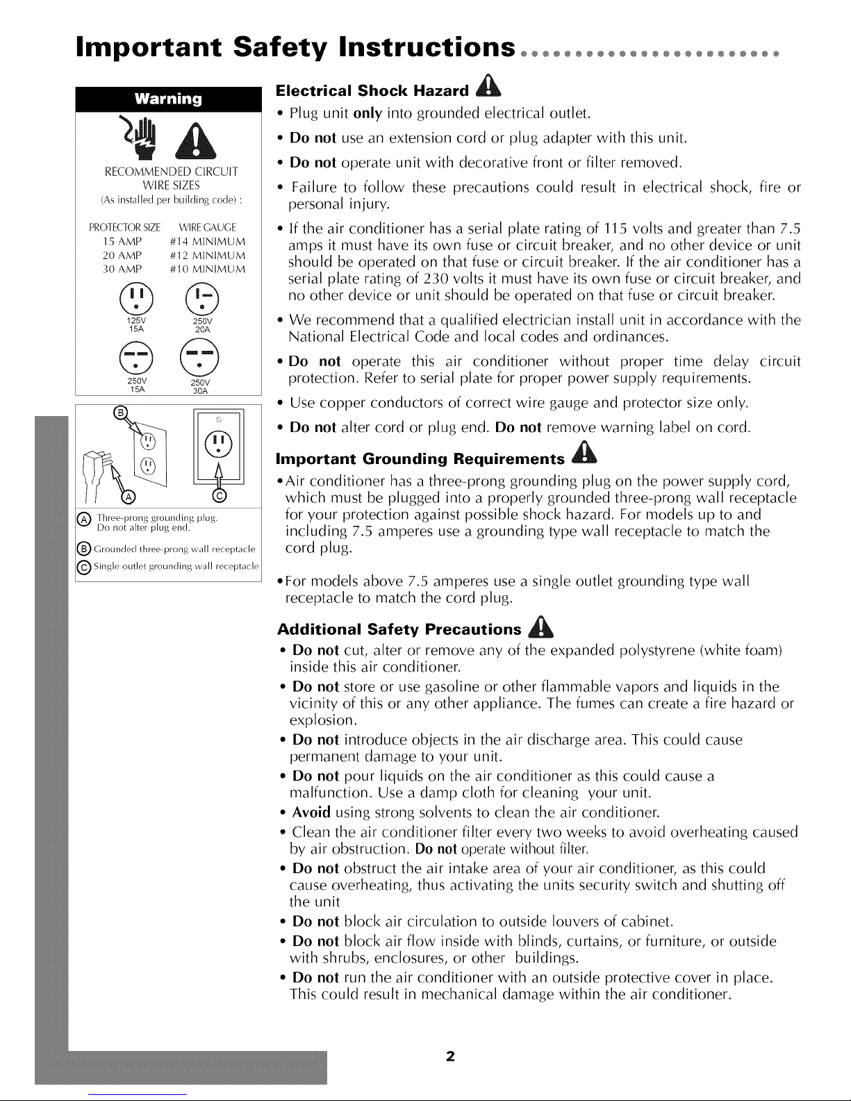
RECOMMENDED CIRCUIT
WIRE SIZES
(As installed per building code) :
PROTECTOR SIZE WIRE GAUGE
15 AMP #14 MINIMUM
20AMP #12 MINIMUM
30 AMP #10 MINIMUM
©©
125V 250V
15A 20A
©©
250V 250V
15A 30A
_) Three-prong grounding plug.
Do not alter plug end.
[_ Grounded three-prong wall receptacle
_) Single outlet grounding wall receptacle
Electrical Shock Hazard
A
• Plug unit only into grounded electrical outlet.
• Do not use an extension cord or plug adapter with this unit.
• Do not operate unit with decorative front or filter removed.
• Failure to follow these precautions could result in electrical shock, fire or
personal injury.
• If the air conditioner has a serial plate rating of 115 volts and greater than 7.5
amps it must have its own fuse or circuit breaker, and no other device or unit
should be operated on that fuse or circuit breaker. If the air conditioner has a
serial plate rating of 230 volts it must have its own fuse or circuit breaker, and
no other device or unit should be operated on that fuse or circuit breaker.
• We recommend that a qualified electrician install unit in accordance with the
National Electrical Code and local codes and ordinances.
• Do not operate this air conditioner without proper time delay circuit
protection. Refer to serial plate for proper power supply requirements.
• Use copper conductors of correct wire gauge and protector size only.
• Do not alter cord or plug end. Do not remove warning label on cord.
k
Important Grounding Requirements
• Air conditioner has a three-prong grounding plug on the power supply cord,
which must be plugged into a properly grounded three-prong wall receptacle
for your protection against possible shock hazard. For models up to and
including 7.5 amperes use a grounding type wall receptacle to match the
cord plug.
• For models above 7.5 amperes use a single outlet grounding type wall
receptacle to match the cord plug.
Additional Safety Precautions
• Do not cut, alter or remove any of the expanded polystyrene (white foam)
inside this air conditioner.
• Do not store or use gasoline or other flammable vapors and liquids in the
vicinity of this or any other appliance. The fumes can create a fire hazard or
explosion.
• Do not introduce objects in the air discharge area. This could cause
permanent damage to your unit.
• Do not pour liquids on the air conditioner as this could cause a
malfunction. Use a damp cloth for cleaning your unit.
• Avoid using strong solvents to clean the air conditioner.
• Clean the air conditioner filter every two weeks to avoid overheating caused
by air obstruction. Do not operate without filter.
• Do not obstruct the air intake area of your air conditioner, as this could
cause overheating, thus activating the units security switch and shutting off
the unit
• Do not block air circulation to outside louvers of cabinet.
• Do not block air flow inside with blinds, curtains, or furniture, or outside
with shrubs, enclosures, or other buildings.
• Do not run the air conditioner with an outside protective cover in place.
This could result in mechanical damage within the air conditioner.
2
Page 3
Installation°°°°°°°°°°°°°°°°°°°°°°°°°°°°°°°°°°°°°°°°°°°°°°°°
Window Requirements:
This air conditioner is factory prepared for installation in standard
double-hung windows with actual opening width of 26 7/8" to 41
5/8" and clear, vertical opening of 15 5/8" minimum from bottom
of sash to sill. Unit can be installed in 23 7/8" wide window, if
cabinet side seals are removed.
Tools Needed
Fastener Identification
Installation Parts Kit contents:
Screwdrivers Ratchet or Driver with 1/4" socket
Item Description
O 1" wood screw
Carpenter's Level Tape Measure
Window Installation
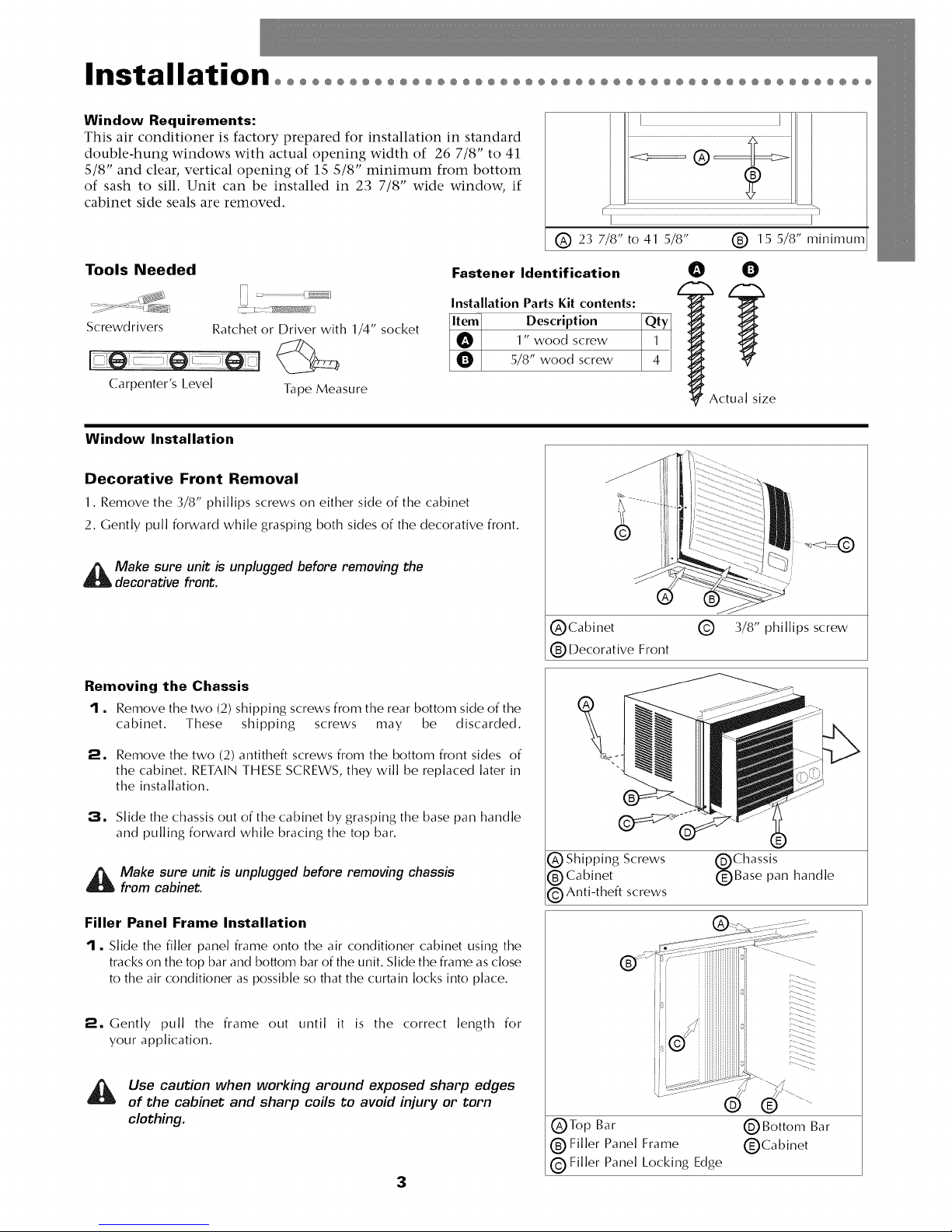
Decorative Front Removal
1. Remove the 3/8" phillips screws on either side of the cabinet
2. Gently pull forward while grasping both sides of the decorative front.
_ ake sure unit is unplugged before removing the
decorative front.
Removing the Chassis
1, Remove the two (2) shipping screws from the rear bottom side of the
cabinet. These shipping screws may be discarded.
O
5/8" wood screw
(_Cabinet (_ 3/8" phillips screw
1_ Decorative Front
4
Actual size
2, Remove the two (2) antitheft screws from the bottom front sides of
the cabinet. RETAIN THESE SCREWS, they will be replaced later in
the installation.
3, Slide the chassis out of the cabinet by grasping the base pan handle
and pulling forward while bracing the top bar.
_ ake sure unit is unplugged before removing chassis
from cabinet.
Filler Panel Frame Installation
I, Slide the filler panel frame onto the air conditioner cabinet using the
tracks on the top bar and bottom bar of the unit. Slide the frame as close
to the air conditioner as possible so that the curtain locks into place.
2, Gently pull the frame out until it is the correct length for
your application.
Use caution when working around exposed sharp edges
of the cabinet and sharp coils to avoid injury or torn
clothing.
3
1_ Shipping Screws (_Chassis
(_)Cabinet (_Base pan handle
1_ Anti-theft screws
(_Top Bar (_Bottom Bar
1_ Filler Panel Frame (_Cabinet
(_Filler Panel Locking Edge
Page 4
Installation°°°°°°°°°°°°°°°°°°°°°°°°°°°°°°°°°°°°°°°°°°°°°°°°°°°° oo
Window Installation (cont.)
I •
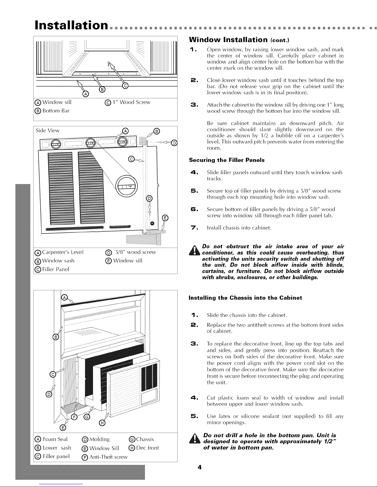
Open window, by raising lower window sash, and mark
the center of window sill. Carefully place cabinet in
window and align center hole on the bottom bar with the
center mark on the window sill.
2. Close lower window sash until it touches behind the top
bar. (Do not release your grip on the cabinet until the
lower window sash is in its final position).
(_ Window sill (_) 1" Wood Screw
(_) Bottom Bar
Side View
3. Attach the cabinet to the window sill by driving one 1" long
wood screw through the bottom bar into the window sill.
Be sure cabinet maintains an downward pitch. Air
conditioner should slant slightly downward on the
outside as shown by 1/2 a bubble off on a carpenter's
level. This outward pitch prevents water from entering the
room.
Securing the Filler Panels
4. Slide filler panels outward until they touch window sash
tracks.
5• Secure top of filler panels by driving a 5/8" wood screw
through each top mounting hole into window sash.
(_ Carpenter's Level
(_ Window sash
(_) Filler Panel
.....0
(_ 5/8" wood screw
(_ Window sill
®
6• Secure bottom of filler panels by driving a 5/8" wood
screw into window sill through each filler panel tab.
7. Install chassis into cabinet.
_ Do not obstruct the air intake area of your air
conditioner, as this could cause overheating, thus
activating the units security switch and shutting off
the unit. Do not block aiflow inside with blinds,
curtains, or furniture. Do not block airflow outside
with shrubs, enclosures, or other buildings.
Installing the Chassis into the Cabinet
I • Slide the chassis into the cabinet.
2 • Replace the two antitheft screws at the bottom front sides
of cabinet.
3•
To replace the decorative front, line up the top tabs and
and sides, and gently press into position. Reattach the
screws on both sides of the decorative front. Make sure
the power cord aligns with the power cord slot on the
bottom of the decorative front. Make sure the decorative
front is secure before reconnecting the plug and operating
the unit.
C) Foam Seal (_Molding C)Chassis
® Lower sash ® Window Sill (_ Dec front
(_ Filler panel Q Anti-Theft screw
4. Cut plastic foam seal to width of window and install
between upper and lower window sash.
5• Use latex or silicone sealant (not supplied) to fill any
minor openings.
_ Do not drill a hole in the bottom pan. Unit is
designed to operate with approximately 1/2"
of water in bottom pan.
4
Page 5

@@@@@@@@@@@@@@@@@@@@@@@@@@@@@@@@@@@@@@@@@@@@@@@@@@@@@@@@@@@@@@@@@@
Installing Cabinet in
Minimum Width Window
I, Remove filler panels on air conditioner cabinet.
2. Refer to steps 1 through 3 of Window Installation instructions.
3. Close window until it touches behind air conditioner top bar.
4. Fasten top bar to window frame using 5/8" washer head screw.
5. If filler is required on sides of air conditioner, cut plastic foam seal
to size and fill both sides.
6. Use silicone or latex sealant (not supplied to fill any minor openings.
7. Install chassis into cabinet.
Consult your authorized dealer or importer for alternative
installation instructions.
Through-the-wall Installation
This air conditioner is designed as a slide-out type chassis, making it
possible to install it through-the-wall in both existing and new
construction. We recommend that this type of installation be performed
with professional assistance.
• IMPORTANT: This appliance must be installed according to all
applicable electrical and building codes and ordinances.
• It is recommended that you have help to install your unit and that you
use proper lifting technique to avoid personal injury.
• It is important that you inspect the condition of the wall where the air
conditioner will be installed.
• Be sure the wall can support the weight of the unit.
• All cabinet louvers MUST BE on the outdoor side of the wall. DO NOT
BLOCK SIDE LOUVERS.
• The cabinet must be installed level from side-to-side and with a
downward tilt from inside to outside.
@
0 Top Bar (_) Attach top bar here
Fig. 1
S:D
Fig. 2
I. First remove the Decorative front panel and chassis from the cabinet,
then remove top bar from the cabinet.
2m
Determine the size of the opening for a wood frame by adding 1/8"
to the width and height of the cabinet. Measure height from top of
cabinet to bottom of bar. Add this measurement to the thickness of
wood used to build the frame. This will determine the size of wall
opening needed. Minimum 1" thick lumber is recommended when
building the frame. When determining finish frame thickness, be sure
not to cover side louvers on the cabinet.
:3, Install the finished frame in the wall opening square and level, nail
or screw it securely to the wall and place the cabinet into the framed
wall opening.
4m
Make sure cabinet projects into the roomside of the wall 1 1/4" at
the top and 1 1/2" at the bottom to ensure proper tilt and access to
the anti-theft screw, then fasten cabinet to the frame by drilling
twelve (12) 1" wood screws (not supplied) through the cabinet and
into the frame. (Fig. 1 &2)
If installation is made in a building with brick veneer construction, a
steel angle lintel must be used to support the bricks above the
cabinet.(Fig.3)
5m
Install a 3/4" X 1 1/2" wood filler strip between the bottom bar and
the interior, caulk both top and bottom of this strip. After cabinet is
installed caulk all openings, inside and outside between finish frame
and cabinet to prevent moisture from getting to the interior of the
wall. Use of flashing (driprail) will further prevent water from
dripping inside the wall.
6. Install chassis into cabinet.
5
Fig. 3
0 Wood frame
1" wood screws
0 Cabinet
0 Bottom Bar
0 Interior wall
0 Decorative Front
0 Minimum lx6 wood
support (nailed or
screwed to wood
frame)
(_2" Wood frame
C)1 1/2" space
(_1 1/4" space
C)Brick veneer
(_ Lintel angle
QCaulking
(_)Flashing (drip rail)
(_Side louvers
(_Wood filler strip
Page 6
Operation°°°°°°°°°°°°°°°°°°°°°°°°°°°°°°°°°°°°°°°°°°°°°°°°°°
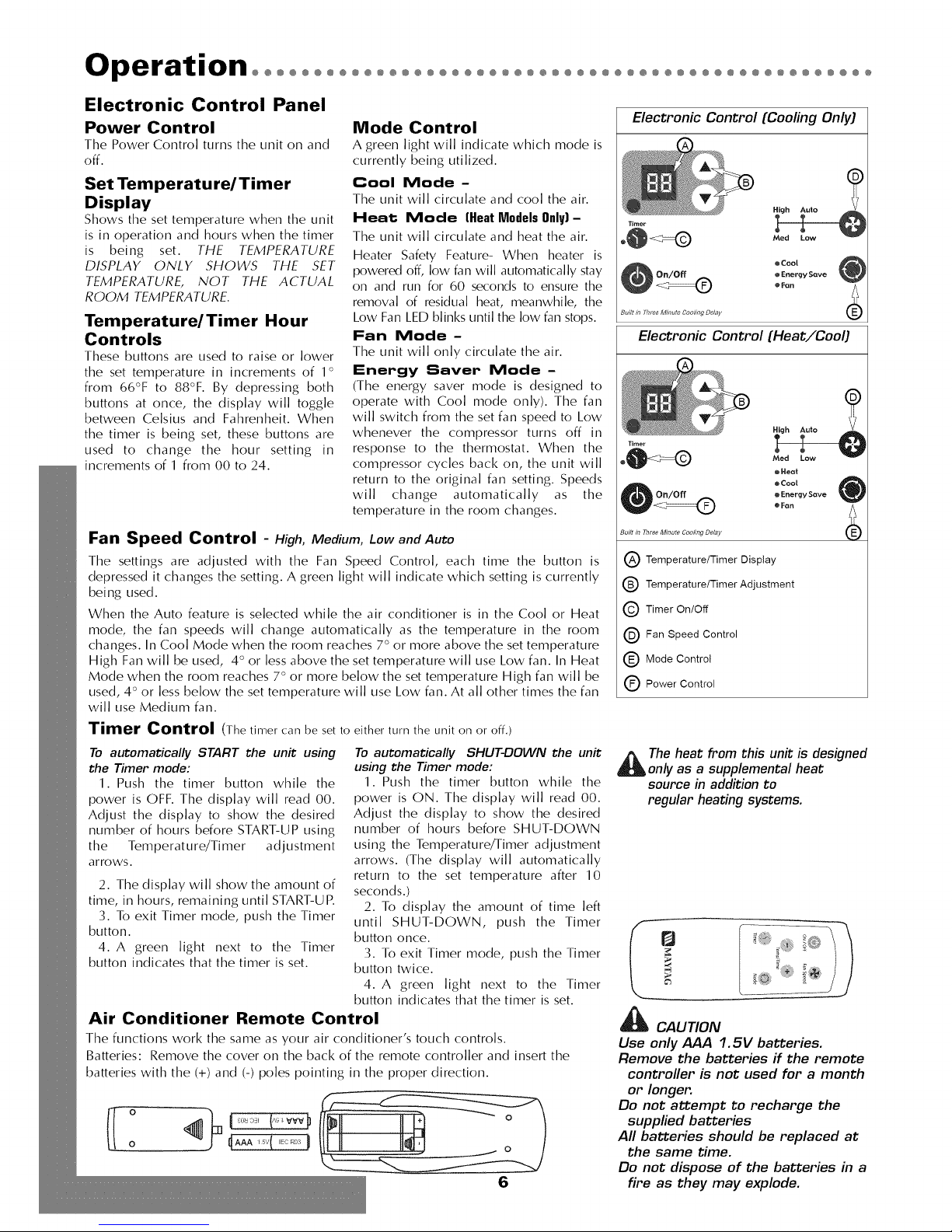
Electronic Control Panel
Power Control
The Power Control turns the unit on and
off.
Set Temperature/Timer
Display
Shows the set temperature when the unit
is in operation and hours when the timer
is being set. THE TEMPERATURE
DISPLAY ONLY SHOWS THE SET
TEMPERATURE, NOT THE ACTUAL
ROOM TEMPERATURE.
Temperature/Timer Hour
Controls
These buttons are used to raise or lower
the set temperature in increments of 1°
from 66°F to 88°F. By depressing both
buttons at once, the display will toggle
between Celsius and Fahrenheit. When
the timer is being set, these buttons are
used to change the hour setting in
increments of 1 from 00 to 24.
Mode Control
A green light will indicate which mode is
currently being utilized.
Cool Mode-
The unit will circulate and cool the air.
Heat Mode (Heat Models Only) -
The unit will circulate and heat the air.
Heater Safety Feature- When heater is
powered off, low fan will automatically stay
on and run for 60 seconds to ensure the
removal of residual heat, meanwhile, the
Low Fan LED blinks until the low fan stops.
Fan Mode-
The unit will only circulate the air.
Energy Saver Mode -
(The energy saver mode is designed to
operate with Cool mode only). The fan
will switch from the set fan speed to Low
whenever the compressor turns off in
response to the thermostat. When the
compressor cycles back on, the unit will
return to the original fan setting. Speeds
will change automatically as the
temperature in the room changes.
Fan Speed Control -High, Medium, Low andAuto
The settings are adjusted with the Fan Speed Control, each time the button is
depressed it changes the setting. A green light will indicate which setting is currently
being used.
When the Auto feature is selected while the air conditioner is in the Cool or Heat
mode, the fan speeds will change automatically as the temperature in the room
changes. In Cool Mode when the room reaches 7 ° or more above the set temperature
High Fan will be used, 4 ° or less above the set temperature will use Low fan. In Heat
Mode when the room reaches 7° or more below the set temperature High fan will be
used, 4 ° or less below the set temperature will use Low fan. At all other times the fan
will use Medium fan.
Timer Control (The timer can be set to either turn the unit on or off.)
To automatically START the unit using
the Timer mode:
1. Push the timer button while the
power is OFF. The display will read 00.
Adjust the display to show the desired
number of hours before START-UP using
the Temperature/Timer adjustment
arrows.
2. The display will show the amount of
time, in hours, remaining until START-UP.
3. To exit Timer mode, push the Timer
button.
4. A green light next to the Timer
button indicates that the timer is set.
To automatically SHUT-DOWN the unit
using the Timer mode:
1. Push the timer button while the
power is ON. The display will read 00.
Adjust the display to show the desired
number of hours before SHUT-DOWN
using the Temperature/Timer adjustment
arrows. (The display will automatically
return to the set temperature after 10
seconds.)
2. To display the amount of time left
until SHUT-DOWN, push the Timer
button once.
3. To exit Timer mode, push the Timer
button twice.
4. A green light next to the Timer
button indicates that the timer is set.
Air Conditioner Remote Control
The functions work the same as your air conditioner's touch controls.
Batteries: Remove the cover on the back of the remote controller and insert the
batteries with the (+) and (-) poles pointing in the proper direction.
o
o
4AAA,sv(......!
6
Electronic Control (Cooling Only)
• Cool
• Energy Save
• Fan
Built in 7hree Minut# Cooling Delay
Electronic Control (Heat/Cool)
Built in Three Minute Cooling Delay
Temperature/Timer Display
Temperature/Timer Adjustment
Timer On/Off
Fan Speed Control
Q Mode Control
Power Control
_ he heat from this unit is designed
only as a supplemental heat
source in addition to
regular heating systems.
r_ ...... _::jo _
%::::_÷
_ CAUTION
Use only AAA 1.5V batteries.
Remove the batteries if the remote
controller is not used for a month
or longer.
Do not attempt to recharge the
supplied batteries
All batteries should be replaced at
the same time.
Do not dispose of the batteries in a
fire as they may explode.
Page 7
®@@@@@@@@@@@@@@@@@@@@
@@@@@@@@@@@@@@@@@@@@@@@@@@@@@@@@@@@@@@@@@@
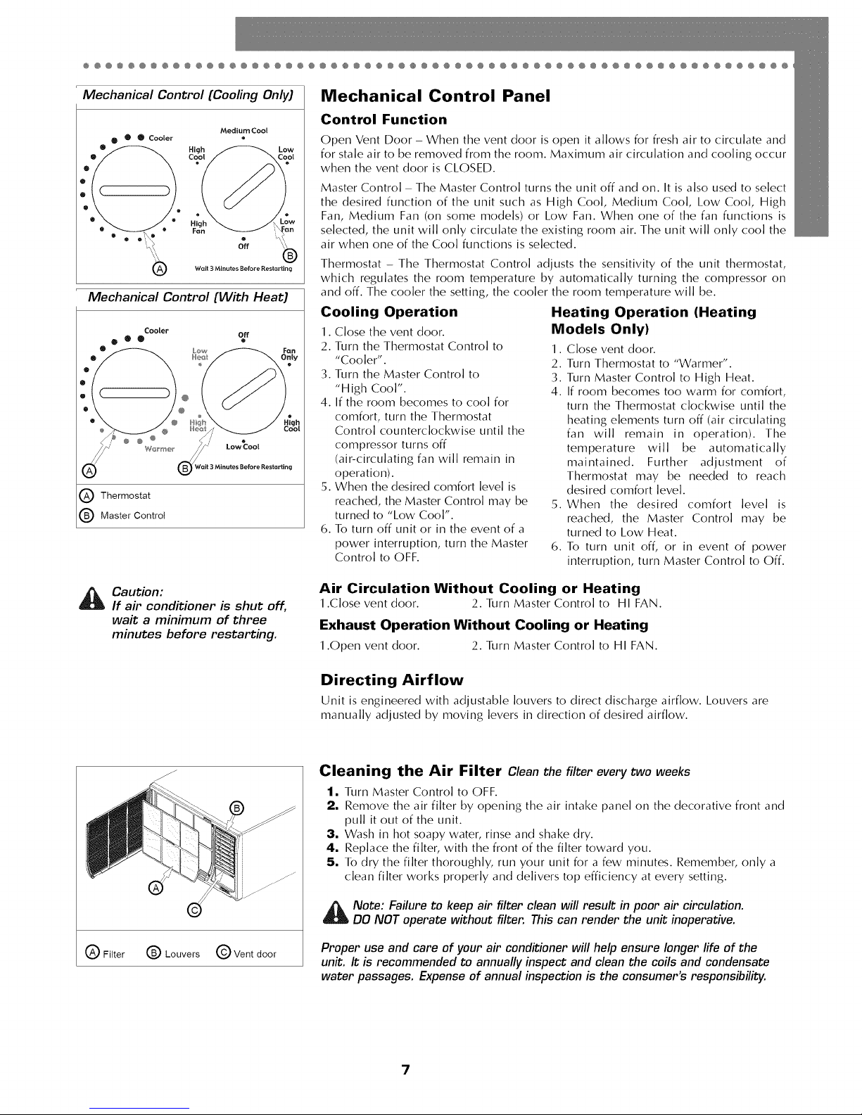
Mechanical Control (Cooling Only)
Walt 3 Minutes Before Restarting
Mechanical Control (With Heat)
Cooler
@e® off
® @ @ /,/ o
(_ Wait 3 Minutes Before Restartino
Q Thermostat
Master Control
Mechanical Control Panel
Control Function
Open Vent Door - When the vent door is open it allows for fresh air to circulate and
for stale air to be removed from the room. Maximum air circulation and cooling occur
when the vent door is CLOSED.
Master Control - The Master Control turns the unit off and on. It is also used to select
the desired function of the unit such as High Cool, Medium Cool, Low Cool, High
Fan, Medium Fan (on some models) or Low Fan. When one of the fan functions is
selected, the unit will only circulate the existing room air. The unit will only cool the
air when one of the Cool functions is selected.
Thermostat - The Thermostat Control adjusts the sensitivity of the unit thermostat,
which regulates the room temperature by automatically turning the compressor on
and off. The cooler the setting, the cooler the room temperature will be.
Cooling Operation
1. Close the vent door.
2. Turn the Thermostat Control to
"Cooler'.
3. Turn the Master Control to
"High Cool".
4. If the room becomes to cool for
comfort, turn the Thermostat
Control counterclockwise until the
compressor turns off
(air-circulating fan will remain in
operation).
5. When the desired comfort level is
reached, the Master Control may be
turned to "Low Cool".
6. To turn off unit or in the event of a
power interruption, turn the Master
Control to OFF.
Heating Operation (Heating
Models Only)
1. Close vent door.
2. Turn Thermostat to "Warmer".
3. Turn Master Control to High Heat.
4. If room becomes too warm for comfort,
turn the Thermostat clockwise until the
heating elements turn off (air circulating
fan will remain in operation). The
temperature will be automatically
maintained. Further adjustment of
Thermostat may be needed to reach
desired comfort level.
5. When the desired comfort level is
reached, the Master Control may be
turned to Low Heat.
6. To turn unit off, or in event of power
interruption, turn Master Control to Off.
_ aution:
If air conditioner is shut off,
wait a minimum of three
minutes before restarting.
Q Filter 1_ Louvers @ Vent door
Air Circulation Without Cooling or Heating
1.Close vent door. 2. Turn Master Control to HI FAN.
Exhaust Operation Without Cooling or Heating
1.Open vent door. 2. Turn Master Control to HI FAN.
Directing Airflow
Unit is engineered with adjustable louvers to direct discharge airflow. Louvers are
manually adjusted by moving levers in direction of desired airflow.
Cleaning the Air Filter Clean the filter every two weeks
1. Turn Master Control to OFF.
2. Remove the air filter by opening the air intake panel on the decorative front and
pull it out of the unit.
;3. Wash in hot soapy water, rinse and shake dry.
4. Replace the filter, with the front of the filter toward you.
5. To dry the filter thoroughly, run your unit for a few minutes. Remember, only a
clean filter works properly and delivers top efficiency at every setting.
_ ote: Failure to keep air filter clean will result in poor air circulation.
DO NOT operate without filter. This can render the unit inoperative.
Proper use and care of your air conditioner will help ensure longer fife of the
unit. It is recommended to annually inspect and clean the coils and condensate
water passages. Expense of annual inspection is the consumer's responsibility.
7
Page 8
Maintenance°°°°°°°°°°°°°°°°°°°°°°°°°°°°°°°°°°°°°°°°°°°°°°
Service To save time and expense, check the following before caning an authorized service station.
Insufficient Cooling
• Turn Master Control to OFF.
• Shut all windows and doors in room.
• Remove any obstructions from inside and outside louvers.
• Close Vent Door (available on some models).
• Inspect filter and clean if dirty.
• Turn Thermostat and Master Controls to coolest settings.
Under certain conditions the cooling coils directly behind the
filter, may ice up and block the airflow. This is a common
occurrence in air conditioners caused when the outside
temperature drops below 70°F (21°C) while the humidity
remains high. If this happens, simply turn the unit off and allow
the ice to melt, then resume normal operation.
Insufficient Heating- Heating Models Only
• Turn Master Control to OFF.
• Shut all windows and doors in room.
• Remove any obstructions from inside and outside louvers.
• Close Vent.
• Turn Thermostat to Warmer and Master Control to HI HEAT.
Unit Fails to Start
• Turn Master Control to OFF.
• Replug line cord plug into outlet to be sure electrical contact
is being made. (If firm contact is not being made, outlet may
have to be replaced).
• Turn Master Control to HI FAN. If air circulating fan does not
operate, check house circuit breaker (or fuses).
For Models Installed in North America - If Service or Parts are Required First, make the recommended checks. If it appears that
service or parts are still required, see your room air conditioner warranty "How to Obtain Warranty Service or Parts".
For Models Installed Outside North America For room air conditioners purchased for use outside North America, the
manufacturer does not extend any warranty either expressed or implied. Consult your local dealer for any warranty terms
extended by the importer in your country.
Visit www.fedders.com for obtaining serviceable parts beyond your warranty period.
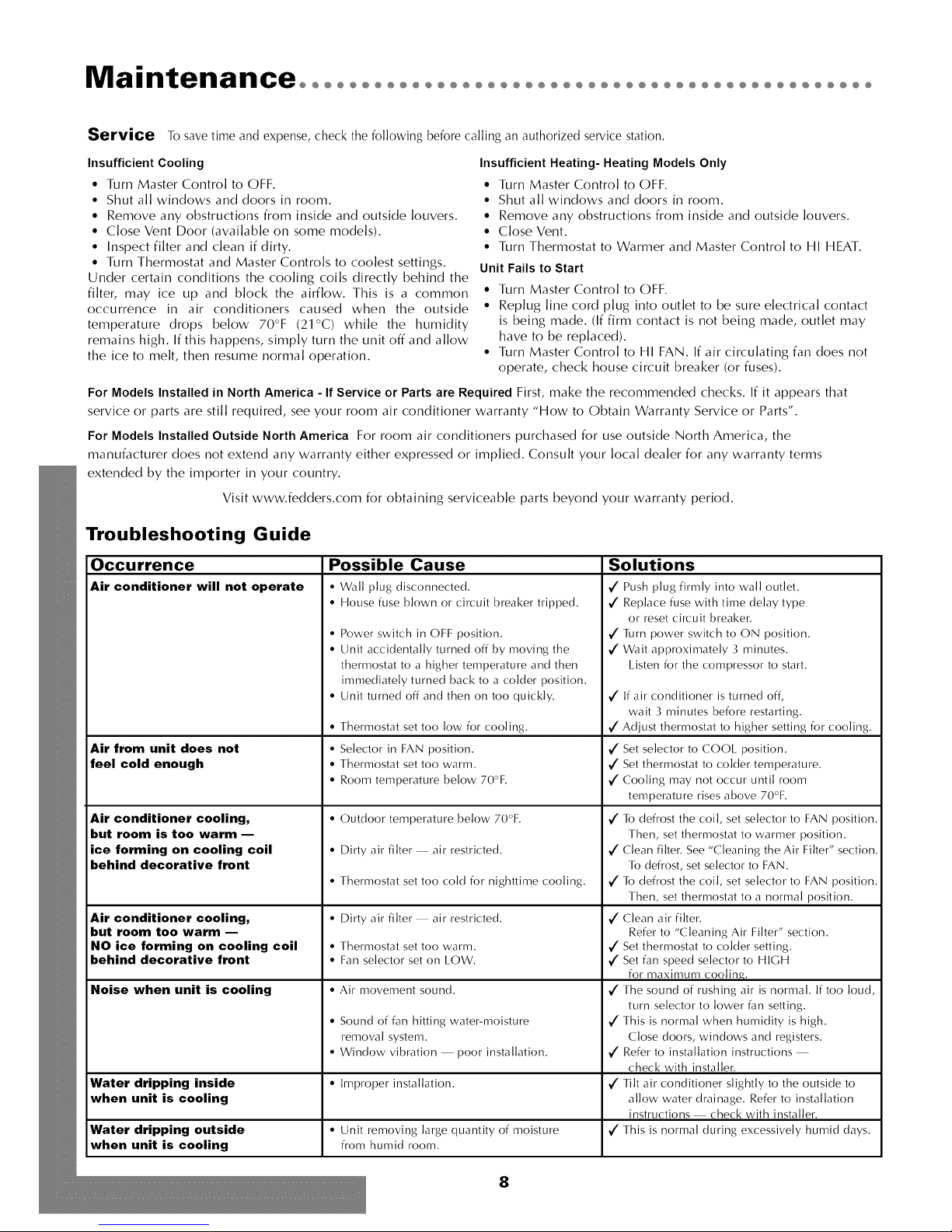
Troubleshooting Guide
Occurrence
Air conditioner will not operate
Air from unit does not
feel cold enough
Air conditioner cooling,
but room is too warm --
ice forming on cooling coil
behind decorative front
Air conditioner cooling,
but room too warm --
NO ice forming on cooling coil
behind decorative front
Noise when unit is cooling
Water dripping inside • Improper installation,
when unit is cooling
Water dripping outside • Unit removing large quantity of moisture 7.
when unit is cooling from humid room,
Possible Cause
• Wall plug disconnected,
• House fuse blown or circuit breaker tripped,
• Power switch in OFF position,
• Unit accidentally turned off by moving the
thermostat to a higher temperature and then
immediately turned back to a colder position,
• Unit turned off and then on too quickly,
• Thermostat set too low for cooling,
• Selector in FAN position,
• Thermostat set too warm,
• Room temperature be]ow 70°F,
• Outdoor temperature below 70°F,
• Dirty air filter air restricted.
• Thermostat set too cold for nighttime cooling.
• Dirty air filter air restricted.
• Thermostat set too warm.
• Fan selector set on LOW.
• Air movement sound.
• Sound of fan hitting water-moisture
removal system,
• Window vibration poor insta]]ation,
Solutions
7. Push plug firmly into wall outlet.
7. Replace fuse with time delay type
or reset circuit breaker.
7. Turn power switch to ON position.
7. Wait approximately 3 minutes.
Listen for the compressor to start.
7. If air conditioner is turned off,
wait 3 minutes before restarting.
7. Adjust thermostat to higher setting for cooling.
7. Set selector to COOL position.
7. Set thermostat to colder temperature.
7. Coding may not occur until room
temperature rises above 70°F.
7. To defrost the coil, set selector to FAN position,
Then, set thermostat to warmer position,
7. Clean filter, See "Cleaning the Air Filter" section,
To defrost, set selector to FAN,
7. To defrost the coil, set selector to FAN position,
Then, set thermostat to a normal position,
7. Clean air filter,
Refer to "Cleaning Air Filter" section,
7. Set thermostat to colder setting,
7. Set fan speed selector to HIGH
for maximum coding,
7 The sound of rushing air is normal, If too loud,
turn selector to lower fan setting.
7. This is normal when humidity is high,
Close doors, windows and registers,
7. Refer to installation instructions
check with installer,
7. Tilt air conditioner slightly to the outside to
allow water drainage, Refer to installation
instructions check with installer,
This is normal during excessively humid days,
8
Page 9
Warrantyooooooooooooooooooooooooooooooooooooooooooooooooooo
For Models Installed
in North America - If Service
or Parts are Required
First, make the recommended checks. If it appears that service or
parts are still required, see your room air conditioner warranty
"How to Obtain Warranty Service or Parts".
For Models Installed
Outside North America
For room air conditioners purchased for use outside North
America, the manufacturer does not extend any warranty either
expressed or implied. Consult your local dealer for any
warranty terms extended by the importer in your country.
Room Air Conditioner Warranty
(Within the 48 contiguous United States, state of Hawaii,
the District of Columbia, Puerto Rico and Canada)
Full (FiveYear) Parts and Labor Warranty
During the five years after the date of original purchase,
Fedders North America will, through its authorized servicers
and free of charge to the owner or any subsequent user, repair
or replace any parts which are defective in material or
workmanship due to normal use. Ready access to the air
conditioner is the responsibility of the owner.
Note: In the event of any required parts replacement
within the period of this warranty, Fedders North America
replacement parts shall be used and will be warranted
only for the period remaining on the original warranty.
Exceptions
The above warranty does not cover failure to function caused
by damage to the unit while in your possession (other than
damage caused by defect or malfunction), or by its improper
installation, or by unreasonable use of the unit, including
without limitation, failure to provide reasonable and necessary
maintenance or to follow the written Installation and Operating
Instructions. If the unit is put to commercial, business, rental, or
other use or application other than for consumer use, we make
no warranties, express or implied, including but not limited to,
any implied warranty of merchantability or fitness for particular
use or purpose.
THE REMEDIES PROVIDED FOR IN THE ABOVE EXPRESS
WARRANTY ARE THE SOLE AND EXCLUSIVE REMEDIES
THEREFOR, NO OTHER EXPRESS WARRANTIES ARE MADE.
ALL IMPLIED WARRANTIES, INCLUDING BUT NOT LIMITED
TO ANY IMPLIED WARRANTY OF MERCHANTABILITY OR
FITNESS FOR A PARTICULAR USE OR PURPOSE, ARE
LIMITED IN DURATION TO FIVE YEARS FROM THE DATE OF
ORIGINAL PURCHASE. IN NO EVENT SHALL FEDDERS
NORTH AMERICA BE LIABLE FOR INDIRECT, INCIDENTAL,
OR CONSEQUENTIAL DAMAGES, EVEN IF ADVISED IN
ADVANCE OF THE POSSIBILITY OF SUCH DAMAGES. NO
WARRANTIES, EXPRESS OR IMPLIED, ARE MADE TO ANY
BUYER UPON RESALE.
Some states do not allow limitations on how long an implied
warranty lasts or do not allow the exclusion or limitation of
incidental or consequential damages, so the above limitations
or exclusions may not apply to you. This warranty gives you
specific legal rights, and you may also have other rights which
may vary from state to state.
No warranties are made for units sold outside of the above
stated areas. Your distributor or final seller may provide a
warranty on units sold outside of these areas.
How to Obtain
Warranty Service or Parts
Service for your room air conditioner will be provided by
CareCo, a division of the manufacturer with authorized
independent CareCo servicers nationwide.
Note: Before calling for service, carefully read the
Installation and Operating Instructions booklet. Then ff
you need service:
1. Call a CareCo authorized servicer and advise them of model
number, serial number, date of purchase and nature of
complaint. Service will be provided during normal working
hours. Contact your dealer for the name of an authorized
servicer if unknown to you.
2. If your dealer is unable to give you the name of a servicer or
if you need other assistance, call the following toll-free
number for the name of an authorized servicer or authorized
parts distributor:
1-866-MAYTAG 1
or you may write:
CareCo, Service Department
415 IN..Wabash Ave., P.O.Box 200
Effingham, IL 62401
Proof of Purchase Date
It is the responsibility of the consumer to establish the original
purchase date for warranty purposes. We recommend that a bill
of sale, cancelled check, or some other appropriate payment
record be kept for that purpose.
Maytagis atrademarkoftheMaytagCorporationandis usedunderlicensebyFeddersNorthAmerica,Inc.
9
Page 10

Instrucciones importantes de seguridad oooooooooooo
Riesgo de Choque Eldctrico
• Enchufe el aparato solamente en un tomacorriente el6ctrico puesto a tierra.
• Con este aparato no use un cord6n de extensi6n ni un adaptador de enchufe.
TAMANOS RECOMENDADOS
DE LOS CONDUCTORES DEL
CIRCUITO
(Instalados segLin el c6digo de
construcci6n) :
CAPACIDAD DE CALIBRE DE LOS
LOS FUSIBLES CONDUCTORES
15 AMP #14 COMO MINIMO
20 AMP #12 COMO MINIMO
30 AMP #10 COMO MINIMO
©©
125V 250V
15A 20A
©©
250V 250V
15A 30A
C) Enchufede tres clavijascon
puesta a tierra. No Modifique.
(_ Tomacorrienteparaenchufe
de tres clavijas conpuestaa
tierra.
Q Tomacorrientemural sencillo
con puestaatierra.
• No haga funcionar el acondicionador de aire sin el panel delantero.
• El incumplimiento de estas precauciones pueden causar un choque el_drico,
incendio o lesi6n personal.
• Si el acondicionador de aire tiene una potencia nominal indicada en la placa de serie
de 115 voltios y de m_isde 7,5 amperes, es necesario que sea protegido con su propio
fusible o disyuntor y ningOn otro dispositivo debe usar ese mismo disyuntor o fusible.
Si el acondicionador de aire tiene una potencia nominal en la placa de serie de 230
voltios, es necesario que seaprotegido con su propio fusible o disyuntor y ningOn otro
aparato debe usar ese mismo disyuntor o fusible.
• Recomendamos que un electricista calificado instale el acondicionador de aire de
acuerdo con el c6digo el6ctrico nacional y los c6digos y reglamentos locales.
• No haga funcionar este acondicionador de aire sin protecci6n adecuada del circuito
de retardo. Consulte la placa de serie para los requerimientos apropiados de
alimentaci6n el6ctrica.
• Use solamente conductores de cobre y fusibles de calibre y capacidad adecuada.
• No modifique el cord6n ni el enchufe del extremo. No retire laetiqueta de advertencia
del cord6n de alimentaci6n.
Requerimientos Importantes para la Puesta a Tierra
• Elcord6n de alirnentaci6n del acondicionador de aire tiene un enchufe de tres clavijas
con puesta a tierra el cual debe ser enchufado en un tomacorriente mural puesto a
tierra de tres alv6olos para su protecciOn contra posible riesgo de choque el6ctrico.
Para los modelos de hasta 7,5 amperes o menos, use un tomacorriente mural del tipo
con puesta a tierra que tenga la misma configuraci6n que el enchufe del cord6n de
alimentaciOn.
• Para los modelos de m_isde 7,5 amperes, use un tomacorriente mural sencillo con
puesta a tierra que tenga la misma configuraci6n que el enchufe del cord6n de
alimentaci6n.
A
A'k
Precauciones de Seguridad Adicionales
• No corte, rnodifique ni retire ning_n pedazo de poliestireno expandido (espurna
blanca) situado dentro de este acondicionador de aire.
• No guarde ni use gasolina u otros vapores y Ifquidos inflamables en la vecindad de
este o cualquier otro artefacto. Los vapores emitidos pueden crear un riesgo de
incendio o explosi6n.
• No introduzca objetos en el _irea de descarga del aire. Esto puede causar da_o
irreparable a su acondicionador de aire.
• No vierta Ifquidos de limpieza en el acondicionador de aire pues esto puede causar
un malfuncionamiento. Use un paffo hOmedo para limpiarlo.
• Evite usar solventes fuertes para limpiar el acondicionador de aire.
• Limpie el filtro del acondicionador de aire cada dos semanas para evitar
sobrecalentamiento causado por obstrucci6n del aire.
• No obstruya el _ireade entrada del aire de su acondicionador, pues esto puede causar
sobrecalentamiento, Io cual activar_i el interruptor de seguridad y apagar_i el aparato.
• No bloquee la circulaci6n del aire hacia las rejillas de ventilaci6n exteriores del
gabi nete.
• No obstruya el flujo del aire hacia el interior con persianas, cortinas o muebles o
hacia el exterior con arbustos, recintos u otros edificios.
• No haga funcionar el acondicionador de aire teniendo instalada la cubierta protectora
exterior. Esto podffa resultar en daffo mec_inico dentro del acondicionador de aire.
10
Page 11

Instalaci6n ooooooooooooooooooooooooooooooooooooooooooooooooo
Dimensiones de la Ventana
Este acondicionador de aire ha sido preparado en la fa'brica para su
instalaci6n en ventanas de guillotina esta'ndares con aberturas de
26,875" a 41,625" de ancho y una abertura vertical de por Io menos
15,625" mfnimo desde la parte inferior de la hoja m6vil hasta el umbral.
El acondicionador de aire puede ser instalado en ventanas de 24" de
ancho, si se retiran los paneles de sellado laterales del gabinete.
Herramientas Necesarias
Destornilladores Llavedetuercasdetrinquete
Nivel Cinta de medir
Identificaci6n deTornillo O (_)
Partida Nombre la parte Cantidad _
Instalacion en la ventana
Desmontaje del Panel Decorative Delantero
1. Retire los tornillos que se encuentran a ambos lados del gabinete.
2. Tire suavemente hacia adelante mientras sostiene
los dos lados del frente decorativo.
_ ntes de desmontaje del chassis, apague la unidad y
desconecte el enchufe.
Desmontaje del Chasis
1, Retire los dos (2) tornillos de embarque* del costado inferior trasero
del gabinete.
2. Retire los dos (2) tornillos antirrobo de ambos lados delanteros
inferiores del gabinete. CONSERVE ESTOS TORNILLOS, ellos sera'n
usados posteriormente en la instalaci6n.
3. Deslice el chasis fuera del gabinete sujetando la manija de la
bandeja inferior y tirando hacia adelante a la vez que sujeta el barra
superior.
Tornillo de madera de 1" 1
Tornillo de madera de 5/8" 4
C) Gabinete C) Delantero Tornillo
(_ Panel Decorativo
*Tornillo para chapa de 3/8"
Instalaci6n del Marco del Panel de Relleno
1, Deslice el marco del panel de relleno en el gabinete del
acondicionador de aire usando las gufas que se encuentran arriba y
abajo de la unidad. Deslice el marco Io ma's cerca posible del
acondicionador de aire para que la cortina quede trabada en la
posici6n adecuada.
2. Tire suavemente del marco hasta obtener la Iongitud que necesita
para realizar la instalaci6n.
Tenga cuidado cuando este trabajando alrededor de/as
esqinas afiladas de/gabinete ara evitar heridas o ropas
rasgadas.
(_Tornillos de embarque (_Chasis
(_)Gabinete !_Manija de la
(_Tornillos antirrobo* bandeja inferior
C) Barra superior @ Barra inferior
(_)Marco del Panel de relleno (_ Gabinete
(_)Borde de fijaci6n
11
Page 12

Instalaci6n ooooooooooooooooooooooooooooooooooooooooooooooooo
Instalacion en la Ventana
I •
Abra la ventana y marque el centro del umbral de la
ventana. Coloque cuidadosamente el gabinete en la
ventana y alinee el agujero central de la barra inferior con
la marca central trazada en el umbral de la ventana.
2•
Cierre la hoja m6vil inferior de la ventana hasta que toque
el aparato detra's de la barra de ret6n superior. (No suelte
A_) Umbral de la ventana (_ Tornillo de 1"
_) Barra inferior
el gabinete hasta que la hoja m6vil inferior est6 en su
posici6n final).
3• Instale el gabinete en el umbral de la ventana colocando un
tornillo de 1" de largo a trav6s de la barra de uni6n inferior
hacia el umbral de la ventana.
Asegureidad de los paneles de relleno
4•
Deslice los paneles de relleno hacia afuera hasta que
toquen los rieles de la hoja m6vil de la ventana.
5•
Asegure la parte superior de los paneles de relleno
instalando tornillos de 5/8" de largo a trav6s de los agujeros
de montaje superiores hacia el umbral de la ventana.
6•
Asegure la parte inferior de los paneles instalando tornillos
de 5/8" de largo en el umbral de la ventana a trav6s de las
leng_]etas del panel de relleno.
C)Nivel C)Tornillo de madera de 5/8"
(_Hoja m6vil de la ventana(_)Umbra I de la ventana
(_Panel de relleno
® ®
C) Espuma de (_ Moldura (_) Chasis
relleno (_ Umbral de
(_) Hoja m6vil la ventana ® Panel
inferior (_ Tornillo decorativo
(_ Panel de antirrobo delantero
relleno
7. Instale el chasis en el gabinete (pa'gina 15).
No obstruya el _rea de la entrada del aire de su
acondicionador, pues esto puede causar
sobrecalentamiento, Io cual activar_ el interruptor de
seguridad y apagar_ el aparato. No bloquee el flujo
del aire hacia el interior con persianas, cortinas o
muebles o hacia el exterior con arbustos, recintos u
otros edificios.
Instalaci6n del Chasis en el Gabinete
I • Deslice el chasis hacia el interior del gabinete.
2• Para reinstalar el panel decorativo delantero, col6quelo en
su lugar y empt_jelo hacia atra's hacia el acondicionador
hasta que entre a presi6n en su lugar. Vuelva a instalar el
tornillo de ret6n detra's del panel de entrada del aire.
3• Reinstale los dos tornillos antirrobo en los lados delanteros
inferiores del gabinete.
4• Corte un relleno de espuma de pla'stico del ancho de la
ventana e insta'lelo entre la hoja m6vil superior e inferior de
la ventana.
5• Use compuesto obturador para Ilenar cualquier abertura
ma's pequeffa.
_ o taladre un agujero en la bandeja inferior. El
acondicionador de aire ha sido diseffado para
funcionar aproximadamente con 1/2" de agua
en la bandeja inferior.
12
Page 13

®@@@@@@@@@@@@@@@@@@@@@@@@@@@@@@@@@@@@@@@@@@@@@@@@@@@@@@@@@®
Instalaci6n del Gabinete en una Ventana
de Ancho Minimo
1. No instale los paneles de relleno en el gabinete.
2. Consulte las instrucciones anteriores desde el paso 1 al 3.
;3. Cierre la ventana hasta que toque detra's de la barra superior del
acondicionador de aire.
4. Asegure la hoja m6vil inferior de la ventana en el marco de la ventana.
T
(_ Barra superior (_)Tornillo de madera de 5/8"
5. Si se requiere relleno en ambos lados del acondicionador de aire, corte
una espuma de pla'stico del tamaffo adecuado y tape ambos lados.
6. Use compuesto obturador para Ilenar cualquier abertura ma'spequeffa.
7. Instale el chasis en el gabinete.
Consulte a su distribuidor autorizado o al importador para obtener
instrucciones de instalaci6n alternativas.
Instalaci6n Empotrado en la Pared
Este acondicionador de aire ha sido dise_ado como un chasis deslizable, haciendo
que sea posible su instalaci6n empotrado en la pared, tanto en muros de
construcci6n antigua como moderna. Recomendamos que este tipo de instalaci6n
sea realizado con ayuda profesional.
• IMPORTANTE: Este aparato debe ser instalado de acuerdo con todos los c6digos
y reglamentos el6ctricos y de construcci6n aplicables.
• Se recomienda que usted solicite ayuda para instalar el aparato y que use una
t6cnica de alzamiento adecuado para evitar lesi6n personal.
• Es importante que usted inspeccione el estado de la pared donde se instalara" el
acondicionador de aire.
• Asegt_rese de que la pared pueda soportar el peso del acondicionador de aire.
• Todas las rejillas de ventilaci6n del gabinete DEBEN QUEDAR hacia el lado
exterior de la pared. NO BLOQUEE LAS REJILLAS DE VENTILACION
LATERALES.
• El gabinete debe ser instalado de modo que quede nivelado de lado a lado y con
una ligera inclinaci6n hacia abajo desde el interior al exterior.
I. Retire primero el panel decorativo delantero y el chasis del gabinete. Retire
la barra superior del gabinete.
12. Determine el tamaffo de la abertura para construir un marco de madera
agregando 1/8" al ancho y a la altura del gabinete. Mida la altura desde la
parte superior del gabinete hasta la barra inferior. Agregue esta medidas al
grosor de la madera usada para construir el marco. Esto determinara" el
tamaffo necesario de la cavidad en la pared. El marco debe construirse
usando madera de por Io menos 1" de espesor. Cuando se determine el
grosor del marco acabado, aseg4rese de que este no cubra las rejillas de
ventilaci6n laterales del gabinete.
;3. Instale el marco terminado en la cavidad mural de manera que quede a
escuadra y nivelado, luego cla'velo o atornfllelo firmemente en la pared e
introduzca el gabinete en la cavidad mural ya preparada con el marco.
,4. Aseg4rese de que el gabinete sobresalga de la pared 1-1/4" en la parte
superior y 1-1/4" en la parte inferior hacia la habitaci6n para asegurar una
(_) Marco de madera
(_ Tornillos de madera de 1"
(_) Gabinete
(_) Barra inferior
[_ Pared
(_) Panel decorativo
delantero
(_ Soporte de madera de
por Io menos 1 x 6
(clavado o atornillado (_ Rejillas ce ventilacion
en e marco de madera)_
(_ Marco de madera de
2" pot todo el rededor
(_ Espacio de 1-1/2"
(_ Espacio de 1-1/4"
(_) Enchapado de ]adril]o
(_ Dintel angular
@ Material obturador
(_ Guardaaguas
(Vierteaguas)
inclinaci6n adecuada y acceso al tornillo antirrobo, luego asegure el
gabinete en el marco instalando doce (12) tornillos de madera de 1" (no
suministrados) a trav6s de los agujeros taladrados en el gabinete y hacia el
marco.
Si el acondicionador se instala en un muro enchapado de ladrillo se debe usar
un dintel angular de acero para sostener los ladrillos que esta'n arriba del
gabinete.
5. Una vez que se haya instalado el gabinete obture todas las aberturas en el
interior y exterior entre el marco acabado y el gabinete para evitar que la
humedad penetre al interior de la pared. El uso de un guardaaguas
(vierteaguas) ayudara" tambi6n a evitar que el agua gotee dentro de la pared.
6. Instale el chasis en el gabinete.
(_ relleno de madera
13
Page 14

FuncionamientOoooooooooooooooooooooooooooooooooooooooooo
Panel de Control Electr6nico
Control de Alimentaci6n
Este bot6n pone en marcha y apaga el
acondicionador de aire.
Indicador deTemperatura de
Ajuste/Temporizador
El indicador muestra la temperatura de
ajuste cuando el acondicionador de aire
esta"en funcionamiento y las horas cuando
se ha activado el temporizador. EL
INDICADOR DE LA TEMPERATURA
SOLAMENTE MUESTRA LA
TEMPERATURA DE AJUSTE, NO LA
TEMPERATURA AMBIENTE REAL.
Control de la Temperatura/
Temporizador
Estos botones se usan para aumentar o
reducir la temperatura de ajuste en
incrementos de 1°, entre 66°F hasta 88°R Si
se oprimen simulta'neamente ambos
botones, el indicador digital cambiara" entre
grados Celsius y Fahrenheit. Cuando se
activa el temporizador, estos botones son
usados para cambiar el ajuste de la hora en
incrementos de 1, entre 00 hasta 24.
El calor proveniente de este
acondicionador de aire ha sido
disefiado solamente como una
fuente de calor suplementario
y no sustituye a los sistemas
de calefaccion regulares.
Selector de Modo
Una luz verde indicara" el modo que esta"
siendo utilizado.
Modo "Cool" (Frio) -
El acondicionador de aire circula y enfrfa el
aire.
Modo 'Heat" (Calor) [Solamente los
Modelos con Calor] -
El acondicionador de aire circula y calienta
el aire.
Caracterfstica de Seguridad del Calentador-
Cuando el calentador esta" apagado, el
ventilador de baja velocidad se activara" y
funcionara" durante 60 segundos para
asegurar la eliminaci6n de algdn calor
residual, a la vez que el diodo LED 'Low
Fan' (ventilador de baja velocidad) destella
hasta que se detenga el ventilador de baja
velocidad.
Modo "Fan" (Ventilador) -
El acondicionador de aire solamente hara"
circular el aire.
Modo "Energy Saver"
(Ahorro de Energia) -
(El modo de ahorro de energfa esta" dise_ado
para funcionar solamente con el modo
'Cool'). El ventilador cambiara" de la
velocidad de ajuste a velocidad baja cuando
el compresor sea apagado por el termostato.
Cuando el compresor se activa nuevamente,
el ventilador volvera" al ajuste original. La
velocidad del ventilador cambia
automa'ticamente segdn cambie la
temperatura en la habitaci6n.
Control Electr6nico
(Enfriamiento Solarnente)
"f°hi°'°
Med Low
® Cool
e Energy Save
• Fen
,g Delay
Control Electr6nico (Calor/Frio)
Timer
o@ =Q .od<ow
@_ o Cool
Built in Three Minute Cooling Delay
Q Indicador de Temperatura/Temporizador
Ajuste de la Temperatura y del
Temporizador
Q Encendido/Apagado del Temporizador
Control de ia Velocidad de[ Ventilador
Q Selector de Modo
Q Control de Alimentaci6n
igh iuto
• Heal
_ Energy Save
o Fan
Control de la Velocidad del Ventilador - Alta, Mediana, Baja yAutom_tica
El ajuste de la velocidad del ventilador se cambia cada vez que se oprime el bot6n de control de velocidad del ventilador. Una
luz verde indicara" el ajuste que se ha seleccionado.
Cuando se selecciona 'Auto' (Automa'tico) y el acondicionador de aire esta" en el modo 'Cool' o 'Heat', la velocidad del ventilador
cambiara" automa'ticamente a medida que cambie la temperatura en la habitaci6n. En el modo 'Cool', cuando la habitaci6n Ilega
a 7° o ma's, sobre la temperatura de ajuste, se usa 'High Fan' (Alta Velocidad), cuando la temperatura en la habitaci6n es de 4 ° o
menos, sobre la temperatura de ajuste, se usa 'Low Fan' (Velocidad Baja). En el modo 'Heat' cuando la habitaci6n alcanza 7 ° o
ma's, bajo la temperatura de ajuste, se usa 'High Fan', cuando la habitaci6n alcance 4° o menos, bajo la temperatura de ajuste, se
usa 'Low Fan'. En todos los otros casos el ventilador usa 'Medium Fan' (velocidad mediana).
Control del Temporizador (El temporizador puede ser ajustado ya sea para encencJer o apagar el acondicionador de aire.)
Para PONER EN MARCHA autom_ticamente el
acondicionador de aire usando el modo "Timer':
1. Oprima el bot6n 'Timer' cuando la alimentaci6n
el6ctrica est6 desconectada. El indicador mostrara" 00.
Ajuste el indicador para que muestre el ndmero de horas
que desea que transcurran antes de la PUESTA EN
MARCHA, usando las flechas de ajuste 'Temperature/Timer'
(Tem peratu ra/Temporizador).
2. El indicador mostrara" la cantidad de horas que faltan
para la PUESTA EN MARCHA.
3. Para salir del modo 'Timer', oprima el bot6n 'Timer'.
4. Una luz verde situada junto al bot6n 'Timer' se
iluminara" para indicar que el 'Timer' esta" activado.
Para APAGAR autom_ticamente el acondicionador de aire
usando el modo "Timer'."
1. Oprima el bot6n 'Timer' cuando la alimentaci6n el6ctrica
est6 conectada. El indicador mostrara" 00. Ajuste el indicador
para que muestre el ndmero de horas que desea que transcurran
antes de que se APAGUE usando las flechas de ajuste
'Temperature/Timer' (Temperatura/Temporizador). (Despu6s de 10
segundos, el indicador volvera" automa'ticamente a la temperatura
de ajuste.)
2. Para ver la cantidad de horas que faltan para que se APAGUE
el acondicionador de aire, oprima una vez el bot6n 'Timer'.
3. Para salir del modo 'Timer', oprima el bot6n 'Timer' dos
veces.
4. Una luz verde situada junto al bot6n 'Timer'se iluminara" para
indicar que el 'Timer' esta" activado.
14
Page 15

Control Mecanico
(Enfriamiento Solamente)
Q 0 0 Cooler
o_f
Wait 3 Minutes Before Restarting
Control Maestro
Termostato
Control Mecanico (Con Calor)
Coole_
0 ® 0 _ff
Panel de Control Mec&nico
Funci6n de Control
Puerta de Ventilaci6n Abierta - Cuando la puerta de ventilaci6n esta" abierta el aire
fresco circula y el aire viciado es extrafdo de la habitaci6n. Se obtiene el enfriamiento
y la circulaci6n ma'xima del aire cuando la puerta de ventilaci6n esta" CERRADA.
Control Maestro - El control maestro enciende y apaga el acondicionador de aire.
Tambi6n se usa para seleccionar la funci6n deseada, tal como Frfo Alto, Fifo Mediano,
Fifo Bajo, Ventilador de Alta Velocidad, Ventilador de Velocidad Mediana (algunos
modelos) o Ventilador de Baja Velocidad. Cuando se selecciona una de las funciones
del ventilador, el acondicionador de aire solamente har4 circular el aire que exista en
la habitaci6n. El acondicionador de aire enfriara" el aire solamente cuando se haya
seleccionado una de las funciones de enfriamiento ('Cool').
Termostato - El control del termostato ajusta la sensibilidad del termostato, que regula
la temperatura de la habitaci6n apagando y encendiendo automa'ticamente el
compresor. Mientras ma's fifo sea el ajuste ma's frfa estara" la habitaci6n.
Enfriamiento
1. Cierre la puerta de ventilaci6n.
2. Gire el control del termostato a la posici6n 'Cooler' (M4s Frfo).
3. Gire el control maestro a 'High Cool' (Frfo Alto).
4. Si la habitaci6n esta" demasiado frfa para ser confortable, gire el control del
termostato a la izquierda hasta que el compresor se apague (el ventilador de
circulaci6n de aire permanecera" en funcionamiento).
5. Cuando se ha Iogrado el nivel de confort deseado, el control maestro puede ser
girado a la posici6n 'Low Cool' (Frfo Bajo).
6. Para apagar el acondicionador de aire o en caso de una interrupci6n de energfa
el6ctrica, gire el control maestro a la posici6n 'OFF' (Apagado).
Calefacci6n (Modelos con Calefacci6n Solamente)
1. Cierre la puerta de ventilaci6n.
2. Gire el termostato a la posici6n 'Warmer' (M4s Caliente).
3. Gire el control maestro a 'High Heat' (Calor Alto).
4. Si la habitaci6n esta" demasiado caliente para ser confortable, gire el termostato a la derecha hasta que se apaguen los
elementos de calefacci6n (el ventilador de circulaci6n del aire permanecera" en funcionamiento). La temperatura se mantendra"
automa'ticamente. Se pueden necesitar ajustes adicionales del termostato para Iograr el nivel de confort deseado.
5. Cuando se Iogra el nivel de confort deseado, el control maestro puede ser girado a 'Low Heat' (Calor Bajo).
6. Para apagar el acondicionador de aire o en caso de una interrupci6n de energfa el6ctrica, gire el control maestro a la posici6n
'OFF' (Apagado).
15
Page 16

MantenimientOoooooooooooooooooooooooooooooooooooooooooooo
Control Remoto del Acondicionador de Aire
Las funciones trabajan igual que los controles manuales de su
acondicionador de aire.
Pilas:
Retire al tapa en la parte trasera del control remoto e inserte las baterias con
los polos (+) y (-) en la direcci6n correcta.
ATENCION
Use solabente pilas AAA o IEC R03 de 1,5V
Retire las pilas si el control remoto no va a ser usado durante un mes o
mas.
No intente recargar las pilas suministradas.
Todas las pilas deben ser reemplazadas a un mismo tiempo.
No incrinere las pilas pues pueden explotar.
Circulaci6n del Aire sin Enfriamiento o Calefacci6n
1. Cierre la puerta de ventilaci6n.
2. Gire el control maestro a 'HI FAN' (Alta Velocidad).
Extracci6n del Aire sin Enfriamiento o Calefacci6n
1. Abra la puerta de ventilaci6n.
2. Gire el control maestro a 'HI FAN' (Alta Velocidad).
C) Filtro
(_) La puerta de ventilaci6n
C) Rejillas de Ventilaci6n
Direcci6n del Flujo del Aire
El acondicionador de aire ha sido dise_ado con rejillas de ventilaci6n ajustables
para orientar el flujo de aire descargado. Las rejillas de ventilaci6n se ajustan
manualmente movi6ndolas en la direcci6n deseada del flujo del aire.
Limpieza del Filtro del Aire
Limpie el filtro cada dos semanas
1. Gire el control maestro a 'OFF' (Apagado).
2. Retire el filtro del aire abriendo el panel de entrada del aire situado en el panel
decorativo delantero y saca'ndolo fuera del acondicionador de aire.
3. La'velo en agua con jab6n, enjuague y sact]dalo para secarlo.
4. Vuelva a colocar el filtro con la parte delantera del filtro dirigida hacia usted.
5. Para secar bien el filtro, haga funcionar el acondicionador de aire durante unos
pocos minutos. Recuerde: solamente un filtro limpio puede proporcionar
eficiencia y funcionar de manera correcta en todos los ajustes.
Nota: Si no se mantiene el filtro del aire limpio puede causar
circulaci6n deficiente del aire. NO haga funcionar el acondicionador
de aire sin el filtro. Esto puede impedir que el acondicionador de aire
funcione.
El uso y cuidado adecuado de su acondicionador de aire le asegurar_
una vida dtil prolongada. Se recomienda que inspeccione anualmente
y limpie las espirales y los pasajes del agua del condensado. El costo
de la inspecci6n anual es responsabilidad del propietario.
Atenci6n: Si se apaga el acondicionador de aire espere por Io
menos tres minutos antes de volver a encenderlo,
16
Page 17

Servicio Para ahorrar tiempo y dinero, verifique 1osiguiente antes de ]]amar a un centro de servicio autorizado.
Enfriamiento Insuficiente
• Coloque el control maestro en ]a posici6n 'OFF' (APAGADO).
• Cierre todas ]as ventanas y puertas de ]a habitaci6n.
• Retire todas ]as obstrucciones de ]as rejillas de ventilaci6n
interiores y exteriores.
• Cierre ]a puerta de ventilaci6n (disponib]e en algunos
modelos).
• Inspeccione el filtro y ]fmpie]o si est_ sucio.
• Gire el termostato y el control maestro al ajuste m_s fifo.
Bajo ciertas condiciones ]as espirales de enfriamiento situadas
directamente detrb,s de] fiitro pueden cubrirse de hie]o y bioquear
el flujo de] aire. Este es un probiema com0n en los
acondicionadores de aire que es causado cuando ]a temperatura
exterior desciende a menos de 70°F (21°C) y ]a humedad
permanece alta. Si esto sucede, simpiemente apague el
acondicionador de aire y deje que se derrita el hielo, ]uego
reanude el funcionamiento normal.
Para losmodelos instalados en Norteamerica - 8i necesita servicio o repuestos Primero, rea]ice ]asverificaciones recomendadas anteriormente.
Si considera de que todavfa es necesario servicio o repuestos, consulte ]a secci6n "Como Obtener Servicio o Repuestos bajo ]a Garanfia" inclufda
en ]a garantfa de su acondicionador de aire individual.
Para modelos vendidos fuera de Norteamerica - Para los acondicionadores de aire comprados para uso fuera de Norteam_rica, el fabricante no
ofrece ninguna garanfia ya sea expresa o impifcita. Consulte a sudistribuidor local para cualquier garanfia que ofrezca el importador en su pals.
Localizaci6n y Soluci6n de Averias
Calefaccion Insuficiente - Modelos con Calefaccion Solamente
• Co]oque el control maestro en ]a posici6n 'OFF (APAGADO).
• Cierre todas ]as ventanas y puertas de ]a habitaci6n.
• Retire todas ]asobstrucciones de ]as rejillas de ventilaci6n interiores y
exteriores.
• Cierre ]a puerta de ventilaci6n.
• Gire el termostato a 'Warmer' (Ma'sCaliente) y el Control Maestro a 'HI
HEAT' (Calor Alto).
El Acondicionador de Aire no Funciona
• Gire el control maestro a 'OFF' (APAGADO).
• Vuelva a enchufar el cord6n el6ctrico en un tomacorriente para
asegurarse que esta" haciendo buen contacto e]F_ctrico. (Si el contacto
no esfirme se debe reempiazar el tomacorriente).
• Gire el control maestro a 'HI FAN' (Alta Velocidad). Si el ventilador de
circulaci6n de] aire no funciona, verifique el disyuntor de] hogar (o los
fusibies).
Problema Soluciones
El acondicionador de aire no funciona
El aire proveniente del acondicionador de
aire no es suficientemente frio
El acondicionador de aire enfria,pero la
habitacionesta demasiado tibia - se forma
hielo en las espirales de enfriarniento
detras del panel decorativo delantero
El acondicionador de aire enfria,pero la
habitacionesta demasiado tibia - NOse
forma hielo en las espirales de
enfriamiento detras del panel decorativo
delantero
Se produce ruido cuando el
acondicionador de aire esta enfriando
Causa Posible
• El enchufe mural est_ desronertado.
• Se ha fundido un fusible o se ha disparado el disyuntor.
• El interruptor principal est4 en la posici6n 'OFF'
(APAGADO).
• El acondicionador de aire fue accidentalmente apagado al
mover el termostato a una temperatura m4s alta y luego se
coloc6 inmediatamente en una posici6n m4s fria.
• El acondicionador de aire se apag6 y luego se encendi6
demasiado r;ipidamente.
• El ajuste del termostato es muy bajo para enfriamiento.
• El selector est;i en la posici6n 'FAN'(Ventilador).
• El termostato est4 en un ajuste demasiado caliente.
• La temperatura de la habitaci6n es inferior a 70°F.
• La temperatura exterior es inferior a 70°F.
• El filtro de aire est_ sucio - restricci6n del aire.
• El termostato est4 en un ajuste demasiado frio para
enfriamiento nocturno.
• Filtro de aire sucio - restricci6n del aire.
El termostato est4 en un ajuste demasiado caliente.
El selector de velocidad del ventilador est,1en una
posici6n 'LOW' (Baja).
Ruido del movimiento delaire.
• Ruido del ventilador al golpear el sistema de extracci6n de
agua y humedad.
• Vibraci6n de la ventana- instalaci6n deficiente.
,/
Inserte bien el enchufe en el tomacorriente mural.
,/
Reemplace el fusible con un tipo de fusible con retardo o reponga
el disyuntor.
,/
Cambie el interruptor principal a la posici6n 'ON' (ENCENDIDO).
,/
Espere aproximadamente 3 minutos. Escuche si el compresor
empieza a funcionar.
,/
Si el acondicionador de aire est4 apagado espere 3 minutos antes
de volver a encenderlo.
,/
Cambie el termostato a un ajuste mzis alto para enfriamiento.
¢
Coloque el selector en un ajuste 'COOL' (Frio).
¢
Coloque el termostato en una temperatura m_s fffa.
¢
No se produciri_ enfriamiento hasta que la temperatura de la
habitaci6n no sea superior a 70°E
¢
Para descongelar la espiral, coloque el selector en la posici6n
'FAN' (Ventilador). Luego coloque el termostato en una posici6n
m_s caliente.
¢
Limpie el filtro, yea la secci6n "Limpieza del Filtro del Aire". Para
descongelar, coloque el selector en la posici6n 'FAN' (Ventilador).
¢
Para descongelar la espiral, coloque el selector en la posici6n
'FAN' (Ventilador). Luego coloque el termostato en una posici6n
normal.
_/ Limpie el filtro del aire. Consulte la secci6n "Limpieza del Filtro
del Aire'.
_/ Coloque el termostato en un ajuste m_s frio.
_/ Coloque el selector de velocidad del ventilador en 'HI' (ALTO) para
enfriamiento m_ximo.
_/ El sonido del aire movi6,ndose es normal. Si es demasiado fuerte,
gire el selector a un ajuste del ventilador m_s bajo.
_/ Esto es normal (uando la humedad es alta. Cierre las puertas,
ventanas y rejillas de ventilaci6n.
_/ Consulte las instrucciones de instalaci6n - consulte con el
instalador.
Goteo de agua dentro del acondicionador
de aire cuando esta enfriando
Goteo de agua fuera del acondicionador de
aire cuando esta enfriando
• Instalaci6n incorrecta.
• El acondicionador de aire esta extrayendo gran cantidad
de humedad de habitaci6n.
Incline ligeramente el acondicionador de aire hacia el exterior para
desaguar el agua. Consulte las instrucciones de instalaci6n -
verifique con el instalador.
_/ Esto es normal durante dias excesivamente h0medos.
17
Page 18

Garantiaoooooooooooooooooooooooooooooooooooooooooooooooooooo
Para modelos instalados en
Norteam6rica - En caso de necesidad
de servicio o piezas
Haga primero las verificaciones recomendadas. En caso
de necesitarse servicio o piezas, consulte en la garantia de
su acondicionador de aire en la secci6n "C6mo obtener
servicio o piezas de garantia".
Para modelos instalados
fuera de Norteam_rica
Para aires acondicionados comprados para uso fuera de
Norteam_rica el fabricante no otorgara" ninguna garantfa
implfcita o explfcita. Consulte a su distribuidor autorizado
sobre las condiciones de la garantfa extendida por el
importador de los equipos de su pals.
Garantia del acondicionador de aire
(Dentro de los 48 estados contiguos de los Estados
Unidos, estado de Hawai, Distrito de Columbia, Puerto
Rico y Canada)
Garantia para todas las piezas (cinco a_os)
y mano de obra
A partir de la fecha de compra y durante un perfodo de cinco
afros, Fedders North America, mediante sus estaciones de
servicio autorizadas, reparara" o reemplazara" sin costo alguno
para el propietario o usuario, cualquier pieza que presente
dafros de material o mano de obra derivados del uso normal
del producto. Es responsabilidad del propietario facilitar el
acceso al acondicionador de aire para realizar los servicios de
reparaci6n.
Nota: En caso de que se requiera reemplazar una pieza
mientras la garantia esta vigente, se utilizaran los
repuestos de Fedders North America los cuales
continuaran en vignecia solamente durante el resto del
periodo de garantia de la unidad.
Excepciones
La garantfa antes indicada no cubre las fallas de
funcionamiento causadas por dafros que sufra la unidad
mientras 6sta est6 en posesi6n del usuario (excluyendo los
dafros causados por defecto o funcionamiento defectuoso), o
por la instalaci6n incorrecta, o la utilizaci6n indebida de la
unidad, incluyendo pero sin limitarse a ello, la negligencia en
proporcionar el mantenimiento necesario y adecuado o en
seguir las "instrucciones de Instalaci6n y Uso" indicadas por
escrito. En caso de utilizarse la unidad para fines comerciales,
de negocios, de arriendo u otro uso o aplicaci6n que no sea el
uso del consumidor, no otorgamos garantfa explfcita ni
implfcita, incluyendo, pero sin limitarse a, toda garantfa
implfcita de negociabilidad o idoneidad para un uso o
finalidad particular.
LAS SOLUCIONES EXPUESTAS EN LA GARANTIA ANTERIOR
SON EXCLUSIVAS. SE RECHAZA CUALQUIER OTRA
GARANTIA YA SEA EXPRESA 0 IMPLICITA, INCLUYENDO,
PERO SIN LIMITARSE A ELLO, TODAS LAS GARANTIAS DE
COMERCIABILIDAD 0 IDONEIDAD PARA UN FIN EN
PARTICULAR DURANTE CINCO ANOS A PARTIR DE LA
FECHA DE COMPRA. BAJO NINGUNA CIRCUNSTANCIA
FEDDERS NORTH AMERICA SE HARA RESPONSABLE POR
NINGUN DANO DIRECTO, INDIRECTO 0
CONSECUENCIAL, SIN IMPORTAR LA CAUSA DE LA
ACCION, AUN CUANDO FEDDERS NORTH AMERICA HAYA
SIDO ADVERTIDO CON ANTERIORIDAD DE LA
POSIBILIDAD DE DICHOS DANOS. NO SE OFRECE
NINGUNA GARANTIA EXPRESA 0 IMPLICITA A
COMPRADORES DESPUES DE LA REVENTA.
Algunos estados no permiten limitar el tiempo de duraci6n de
una garantfa implfcita ni permiten excluir ni limitar los dafros
incidentales o emergentes, de modo que las limitaciones o
exclusiones antes indicadas podrfan no aplicarse en su caso.
Esta garantfa le otorga derechos legales especfficos. Usted
podrfa tener tambi6n otros derechos que pueden variar de
estado a estado.
No se ofrecen garantfas para las unidades vendidas fuera de las
a'reas antes indicadas. Su distribuidor o vendedor final podrfa
proporcionar una garantfa para las unidades vendidas fuera de
estas a'reas.
C6rno obtener servicio
o piezas de garantia
El servicio para su acondicionador de aire sera" provisto por
CareCo, una divisi6n del fabricante con estaciones de servicio
independientes CareCo autorizadas en todo el pals.
Nora: Antes de solicitar servicio, lea cuidadosamente el
folleto de "lnstrucciones de Instalacion y Uso'."Luego, si
necesita servicio:
1. Llame a un taller de servicio autorizado CareCo y
suminfstreles el n0mero de modelo, n0mero de serie, la fecha
de compra y la naturaleza del problema. El servicio se
prestara" durante horas normales de trabajo. Comunfquese con
su distribuidor para obtener recomendaciones sobre una
estaci6nde servicio autorizada.
2. Si su distribuidor no puede proporcionarle el nombre de un
taller de servicio o si necesita otro tipo de asistencia, Ilame
al siguiente n0mero gratis para obtener el nombre de un
taller de servicio autorizado o distribuidor de piezas
autorizado:
1-866-MAYTAG 1
o escriba al."
Departamente de Servicio de CareCo
415 IN..Wabash Ave., RO. Box 200
Effingham, IL 62401 EE. UU.
Prueba de la fecha de compra
El establecimiento de la fecha de compra original para efectos
de la garantfa es responsabilidad del consumidor.
Recomendamos mantener la factura de compra, el cheque
cancelado o alg0n otro registro de pago apropiado para dicho
efecto.
18
Page 19

Directives de s6curit6
Risque de choc _lectrique _J_
• Brancher I'appareil uniquernent sur une prise de courant _lectrique reli_e _ la terre.
• Ne pas utiliser ave(: cet appareil un c._ble de rallonge ou un adaptateur de fiche.
• Ne pas faire fonctionner cet appareil Iorsque le panneau de facade est enlev6.
• Le non-respect de ces pr6cautions peut entratner choc 61ectrique, incendie ou
CALIBRE RECOMMAND[_ DES
CONDUCTEURS
(selon le code du b_timent) :
CAPACITE CALIBRE DES
DU FUSIBLE CONDUCTEURS
15A N° 14ou plus gros
20 A N° 12 ou plus gros
30 A N° 10 ou plus gros
©©
125V 250V
15A 20A
©©
250V 250V
15A 30A
(_ Fiche de branchement _ trois
broches(liaison_ laterre).
Ne pasmodifier la fiche de
branchement.
1_) Prises de courant murales
trois alv6oles(liaison _ la terre).
(_ Prise de courant murale simple
avec liaison _ la terre.
blessures.
• Si les param6tres d'alimentation 61ectrique sur la plaque signal6tique sont 115 volts et
7,5 A ou plus, il faut que I'appareil soit prot6g6 par son propre fusible ou disjoncteur,
et aucun autre appareil ne devrait 6tre branch6 sur le m6me circuit d'alimentation. Si
la plaque signal6tique du climatiseur indique qu'il doit 6tre aliment6 sous 230 volts,
il faut que I'appareil soit prot6g6 par son propre fusible ou disjoncteur, et aucun autre
appareil ne devrait 6tre branch6 sur le m6me circuit d'alimentation.
• II est recommand6 qu'un 61ectricien qualifi6 installe I'appareil conform6ment aux
prescriptions du code national des installations 61ectriques et des (:odes et r6glements
Iocaux appl icables.
• Ne pas faire fonctionner ce climatiseur si le circuit d'alimentation n'est pas prot6g6 par
un fusible ou disjoncteur chrometr6 de capacit6 convenable. Pour les caract6ristiques
d'alimentation 61ectrique, voir la plaque signal6tique de I'appareil.
• Utiliser uniquement des conducteurs en cuivre et dispositifs de protection de calibre
et de capacit6 ad6quate.
• Ne pas modifier le cordon d'alimentation ou la fiche de branchement. N'enlever
aucune 6tiquette d'avertissement fix6e sur le cordon d'alimentation.
Liaison _ la terre - Exigences importantes
• Pour la protection des utilisateurs contre les risques de choc dectrique, le clirnatiseur
comporte un cordon d'alimentation muni d'une fiche de branchement ._trois broches
(liaison _ la terre) qu'on doit brancher sur une prise de courant murale _ trois alv6oles
convenablement reli6e _ la terre. Pour un module dont la demande de courant est de
7,5 A ou moins, utiliser une prise de courant murale reli6e _ la terre de m6me
configuration que la fiche de branchement.
• Pour un module dont la demande de courant est sup6rieure _ 7,5 A, utiliser une prise
de courant simple avec liaison _ la terre, de m6me configuration que la fiche de
branchement.
Mesures de s_curit_ additionnelles
•Ne pas couper, modifier ou enlever aucun des cornposants de polystyrene expans_
(materiel isolant blanc) plac6s _ I'int6rieur du climatiseur.
• Ne jamais remiser ou utiliser d'essence ou autre produit inflammable liquide ou
gazeux au voisinage des appareils ou de tout autre appareil m6nager. Les vapeurs
6mises pourraient entratner un risque d'incendie ou d'explosion.
• N'introduire aucun objet clans la zone de d6charge de I'air; ceci pourrait provoquer
une d6t6rioration non r6parable de I'appareil.
• Ne verser aucun liquide sur le climatiseur; ceci pourrait entratner une anomalie de
fonctionnement. Pour le nettoyage de I'appareil, utiliser un chiffon humide.
• Lors du nettoyage du climatiseur, 6viter d'employer un solvant 6nergique.
• Pour 6viter une obstruction et un 6chauffement excessif, nettoyer le filtre du
climatiseur _ intervalles de deux semaines.
• Veiller _ ne pas obstruer les entr6es d'air du climatiseur; ceci provoquerait un
6chauffement excessif et le d6clenchement des dispositifs de s6curit6 qui provoquent
I'arr6t de I'appareil.
• Ne pas bloquer la circulation de I'air vers les claires-voies ext6rieures de la caisse.
• Ne pas bloquer la circulation de I'air au voisinage de I'appareil, _ I'int6rieur (stores,
rideaux, meubles), ou _ I'ext6rieur (arbustes, enceintes ou autre b._timent).
• Ne pas faire fonctionner le climatiseur Iorsque la housse de protection est en place.
Ceci pourrait faire subir des dommages m6caniques au climatiseur.
; ,, * *.m vor.an.es ooooooooooooooooooooo
19
z%
Page 20

Montage°°°°°°°°°°°°°°°°°°°°°°°°°°°°°°°°°°°°°°°°°°°°°°°°°°°°
Dimensions de la fen_tre
Ce climatiseur a 6t6 configur6 _ I'usine pour I'installation dans une
fen6tre _ guillotine standard (double) offrant une largeur libre de 68,3 cm
(26,875 po) _ 105,7 cm (41,625 po) et une hauteur libre d'au moins 39,7
cm (15,625 po) (depuis le bas de I'ouvrant mobile jusqu'au seuil de
fen6tre). On peut installer I'appareil dans une fen6tre offrant une largeur
libre de 3/8 po, apr_s d6pose des joints lat6raux.
Outillage n6cessaire
Contenu de I'ensemble d'installation
Tournevis
N ivea u
CI6 _ cliquet
Ruban _ mesurer
No. Nom de la piece Q't6
g Vis a bois - 25ram (lpo) 1
Vis a bois 15.875mm (5/8 po) 5
Installation dans un frente
Enlevement du panneau de facade d6coratif
1. Retirer les vis de chaque c6t6 de la caisse.
60 cm (23-5/8 po) _ 39,7 cm (15,625 po)
C) 105,7 cm (41-5/8 po) (_) rain,
2. Tirer avec pr6caution vers I'avant tout tenant bien les deux c6t6s du
panneau de facade.
IZenlevement du chassis
1. En bas, _ I'arribre de la caisse, sur les c6t6s, enlever les deux (2) vis
plac6es avant I'exp6dition.
2. En bas, _ I'avant, sur les c6t6s de la caisse, 6ter les deux (2) vis
antivol. CONSERVER CES VIS; elles seront r6utilis6es durant
I'installation.
3. Faire glisser le chassis pour le faire sortir de la caisse - saisir la
poign6e du plateau et tirer vers I'avant.
"3/8" sheet metal screw
Installation des panneaux de remplissage
1. Faire coulisser le cadre du panneau de remplissage sur la caisse du
climatiseur en utilisant les tringle sup6rieure et inf6rieure de
I'appareil. Faire coulisser le cadre aussi pr6s que possible du
climatiseur de mani6re que le rideau se verrouille en place.
C) Caisse C) Panneau de facade
(_ Vis de phillips d6coratif
(_Vis utilis6es pour I'exp6dition @ Chassis
(_)Caisse (_ Poign6e
(_Vis antivol
2. Tirer sur le cadre avec pr6caution jusqu'_ ce qu'il se trouve _ la bonne
Iongueur.
Travailler prudemment au voisinage des ar_tes
expos_es de la caisse et des ar_tes acCrUes de
I'_changeur de chaleur, pour _viter de se blesser ou
de d_chirer les v_tements.
C)Tringle sup6rieure (_ Bord de verrouillage
(_)Cadre du Panneau de (_ Tringle inf6rieure
remplissage C) Caisse
20
Page 21

C)Seuildefen@tre(]_)Tringle (_ Visabois-
inf6rieure 25mm(1po)
VueLat6rale
L_
C) Niveau (_Vis _ bois - 5/8 po
(_) Ouvrant inf_rieur (_)Seuil de fen6tre
(_ Panneau de remplissage
Installation dans un fentre
1 •
Ouvrir la fen6tre et marquer la position du centre sur le
seuil de fen6tre. Positionner prudemment la caisse dans la
fen6tre; aligner le trou central de la tringle inf6rieure avec
la marque de centrage trac6e sur le seuil de fen6tre.
Abaisser I'ouvrant inf6rieur de la fen6tre pour le placer au
contact de la caisse, derriere la tringle de retenue
sup6rieure. (Ne pas I_cher la caisse avant que I'ouvrant
inf6rieur soit _ sa position finale.)
3•
Fixer la caisse sur le seuil de la fen6tre : placer une vis de
1 po _ travers la tringle inf6rieure, dans le seuil de fen6tre.
Veiller _ ce que la caisse demeure inclin6e vers I'ext6rieur.
II faut que le climatiseur soit 16g@rement inclin6 vers
I'ext6rieur, vers le bas (bulle du niveau d6cal6e de
1/2 bulle); cette 16g_re inclinaison vers I'ext6rieur
emp6chera I'eau de p6n6trer dans la pi@ce.
Installation des panneaux de remplissage
4. Faire coulisser les panneaux de remplissage vers I'ext6rieur
pour les placer en contact avec le fond des rainures
verticales des chambranles de fen6tre.
5, Immobiliser chaque panneau de remplissage au sommet
avec des vis de 5/8 po plac6es dans I'ouvrant _ travers les
trous de montage sup6rieurs.
6• Immobiliser le bas des panneaux de remplissage avec des
vis de 5/8 po plac6es dans le seuil de fen6tre _ travers les
onglets des panneaux de remplissage.
7• Installer le chassis dans la caisse.
Veiller _ ne pas obstruer les entr_es d'air du climatiseur;
ceci provoquerait un _chauffement excessif et le
d_clenchement des dispositifs de s_curit_ qui
provoquent I'arr_t de I'appareil. Ne pas bloquer la
circulation de I'air au voisinage de I'appareil, _ I'int_rieur
(stores, rideaux, meubles), ou _ I'ext_rieur (arbustes,
enceintes ou autre b_timent).
®
C) Joint en C) Moulure
mousse (_ Seuil de
(_ Ouvrant fen6tre
inf6rieur C) vis antivol
(_ Panneau de C) Chassis du
remplissage climatiseur
(_Panneau
de facade
d6coratif
Installation du chassis dans la caisse
I •
Faire glisser le chassis dans la caisse.
2.
Placer le sommet du panneau de facade d6coratif _ sa
position normale; pivoter vers I'arri@re, vers I'appareil, pour
provoquer I'emboitement et la mise en place. R6installer la
vis de retenue derri@re le panneau d'admission d'air.
3•
R6installer les deux vis antivol en bas, _ I'avant, sur les c6t6s
de la caisse.
4.
Couper des joints en mousse de plastique _ la Iongueur
correspondant _ la largeur de la fen6tre; installer ces joints
entre les panneaux ouvrants mobiles sup6rieur et inf6rieur
de la fen6tre.
5•
Utiliser un calfeutrant pour remplir toute ouverture
mineure.
Ne jamais percer un trou clans le plateau de
r_cup_ration inf_rieur. L'appareil est con_u
pour fonctionner avec environ 13 mm (1/2
po) d'eau clans le plateau de r_cup_ration.
21
Page 22

Montage°°°°°°°°°°°°°
I
i ilii
i ili i
i i1_[
i
i i
(_ Tringle superior (_) Visa bois - 25mm (1po)
C) Encadrement en bois
(_Vis _ bois- 1 po
C) Caisse
C) Tringle inf6rieure
(_ I'int6rieur de la piece
C) Panneau de facade
d6coratif
(_ Support en bois -
minimum 2,5 x 15,2 cm
(1 x 6 po) (fixation sur (_)Claires-Voie:
I'encadrement en bois lat6rales
par clous ou vis) C) Panneau de bois
Encadrement en bois
Q5 cmx 5cm (2pox 2po),
tout autour
(_ Espace -3,8 cm (1-1/2 po)
(_ Espace -3,2 cm(1-1/4po)
C) Parement de briques
(_ Corni_re de linteau
Q Calfeutrage
(_ Sol in (6goutiementde
@@@@@@@@@@@@@@@@@@@@@@@@@@@@@@@@@@@@@@@
Installation de la caisse dans une fen6tre
de largeur minimale
1. Ne pas installer les panneaux de remplissage sur la caisse du climatiseur.
2. Voir les 6tapes 1 _ 7 des instructions pr6c6dentes.
3. Abaisser I'ouvrant jusqu'au contact avec la caisse, derriere la tringle
sup6rieure du climatiseur.
4. Assujettir I'ouvrant inf6rieur avec le chassis de la fen6tre (utiliser cloths, vis
bois ou brides en 6querre).
5. S'il reste des espaces _ remplir sur les c6t6s du climatiseur, les remplir avec des
morceaux en polystyrene ou mousse de plastique, coup6s _ la taille appropri6e
(des deux c6t6s).
6. Utiliser un calfeutrant pour remplir route ouverture mineure.
7. Installer le chassis dans la caisse.
Pour une autre configuration d'installation, demander les instructions appropri6es
I'importateur ou au revendeur agr66.
Installation _ travers un tour
La conception de ce climatiseur permet son extraction hors de la caisse par
coulissement, ce qui permet I'emploi de la caisse comme gaine murale pour
I'installation _ travers un mur - b_timent existant ou construction neuve. Nous
recommandons que ce type d'installation soit ex6cut6 avec I'assistance d'un
professionnel.
• IMPORTANT : Lors de I'installation de cet appareil, on doit respecter les
prescriptions du code du b_timent, du code des installations 61ectriques, et des
r_glements Iocaux en vigueur.
• Pour 6viter des blessures, employer les techniques de levage appropri6es, et
demander la participation d'un assistant.
• II est important de v6rifier le bon 6tat du mur dans lequel le climatiseur sera
install6.
• V6rifier que lemur peut soutenir le poids du climatiseur.
• Toutes les claires-voies de la caisse du climatiseur DOIVENT SE TROUVER
I'ext6rieur du mur. VEILLER A NE PAS OBSTRUER LES CLAIRES-VOIES
LATI_RALES.
• La caisse doit 6tre d'aplomb lat6ralement, et 16g_rement inclin6e vers I'ext6rieur.
1. Enlever d'abord le panneau de facade d6coratif, puis retirer le chassis de la
caisse. Oter la tringle sup6rieure de la caisse.
2. D6terminer les dimensions de I'ouverture que devra former un encadrement
en bois : ajouter 3,2 mm (1/8 po) _ la largeur et _ la hauteur de la caisse.
Mesurer la hauteur depuis le sommet de la caisse jusqu'_ la limite inf6rieure
de la tringle. Ajouter cette dimension _ 1'6paisseur des barres en bois
utilis6es pour la r6alisation de I'encadrement. Ceci d6terminera la taille de
I'ouverture n6cessaire dans lemur. Pour la r6alisation de I'encadrement,
utiliser du bois 6pais d'au moins 2,5 mm (1 po). Pour d6terminer la largeur
finale de I'encadrement, tenir compte du fair que les claires-voies lat6rales
de la caisse doivent 6tre totalement d6gag6es.
3. Installer I'encadrement en bois dans I'ouverture murale; contr61er I'aplomb
et 1'6querrage; fixer solidement par clous ou vis sur le mur, et placer la caisse
dans I'ouverture de I'encadrement r6alis6e dans lemur.
4. Veiller _ ce que la caisse d6passe en saillie _ I'int6rieur de la piece, de 3,2
cm (1-1/4 po) au sommet et de 3,8 cm (1-1/2 po) en bas; ceci produira
I'inclinaison appropri6e et permettra I'acc_s aux vis antivol. Fixer ensuite la
caisse _ I'encadrement _ I'aide de douze (12) vis _ bois de 1 po (non
fournies), _ travers des troths perc6s dans la caisse.
Si le b_timent comporte un parement de briques, on devra utiliser une corni_re
en acier pour soutenir les briques au-dessus de la caisse du climatiseur.
5. Apr_s I'installation de la caisse, calfeutrer routes les ouvertures _ I'int6rieur
et I'ext6rieur entre I'encadrement en bois et la caisse, pour emp6cher
I'introduction d'humidit6 _ I'int6rieur du mur. L'emploi d'un solin (flashing)
contribuera 6galement _ emp6cher I'eau de s'introduire _ I'int6rieur du mur.
6. Installer le chassis du climatiseur dans la caisse.
22
Page 23

Fonctionnement ooooooooooooooooooooooooooooooooooooooooo
Tableau de commande 6lectronique
Commande marche/arr6t
Ce bouton commande la raise en marche et
I'arr6t de I'appareil.
Affichage
tempdraturelminuterie
Cet afficheur pr6sente la temp6rature de
r6glage Iorsque le climatiseur fonctionne, et
la dur6e Iors du r6glage de la p6riode de
minutage. L'INDICATION DE TEMPI_RA-
TURE CORRESPOND ,_ LA TEMPI_RATURE
DE RI_GLAGE, ET NON PAS ,_ LA
TEMPI_RATURE RI_ELLE DANS LA PIECE.
Commandes de
temp_rature/minuterie
Ces boutons permettent d'augmenter ou
diminuer la temp6rature de r6glage par
intervalle de 0,6 °C (1 °F), entre ] 9 et 31 °C
(66 et 88 °F). Si on appuie simultan6ment
sur les deux boutons, I'affichage de
temp6rature permute entre degr6s Celsius et
degr6s Fahrenheit. Lors du r6glage de la
minuterie, ces boutons font changer le
r6glage de I'heure, par intervalle d'une
heure, entre O0 et 24.
S_lecteur de mode
Un t6moin vert indique quel mode est
actuellement utilis6.
Mode de refroidissement -
Circulation de I'air avec refroidissement.
Mode de chauffage (seulement
pour un module avec chauffage) -
Cet appareil peut r6chauffer I'air qu'il fair
circular.
Mesure de s6curit6 pour la fonction de
chauffage- Lorsqu'on interrompt I'alimen-
ration de 1'616ment chauffant, le ventilateur
continue _ fonctionner (basse vitesse)
pendant 60 secondes pour 1'6vacuation du
r6sidu de chaleur, tandis qua le t6moin DEL
vitesse basse clignote jusqu'_ I'arr6t du
venti lateur.
Mode de ventilation -
L'appareil ne fair qua circular I'air.
Mode d'_conomie d'_nergie -
La fonction <<6conomie d'6nergie>; n'est
utilis6e qu'avec le mode de refroidissement.
Lorsque le compresseur cesse de
fonctionner sur commande du thermostat, le
ventilateur adopte automatiquement la
VITESSE BASSE, quelle qua soit la vitesse de
rotation initialement s61ectionn6e. Lors de
la remise en marche du compresseur sur
commande du thermostat, le ventilateur
adopte de nouveau la vitesse de rotation
initialement s61ectionn6e. La vitesse du
ventilateur change automatiquement, salon
1'6volution de la temp6rature dans la piece.
Tableau de commande electronique
(refroidissement seulement)
High A to
®
E_ergy Sove
®Fen
Tableau de cammande
electranique
(chauffage/refroidissement)
guilt in Tht#_ Mfnut_ Coolsng O_A_y
Q Affichage temperature/minuterie
@ Reglage temperature/minuterie
Q Minuterie - marche/arr_t
Ventilateur - selecteur de vitesse
(_ Selecteur de mode
Q Commande marche/arr_t
H_t
¢ool @Energy S_va
F_n /,
A
Sdlecteur de la vitesse du ventUateur -
elevee, moyenne, basse et autom.
Chaque pression sur le bouton fair changer la vitesse s61ectionn6e pour le
fonctionnement du ventilateur. Un t6moin vert indique quelle vitesse est actuellement
s61ectionn6e.
Lorsque le mode Autom. est s61ectionn6, durant le fonctionnement du climatiseur au
mode de refroidissement ou de chauffage, la vitesse du ventilateur change
automatiquement en fonction de la temp6rature qui r_gne dans la piece. Au mode de
refroidissement, Iorsque la temp6rature dans la piece est sup6rieure de 4 °C (7 °F) ou
plus _ la temp6rature de r6glage, la vitesse 61ev6e du ventilateur est utilis6e; Iorsque
la temp6rature dans la piece est sup6rieure de 2 °C (4 °F) ou mains _ la temp6rature
de r6glage, la vitesse basse est utilis6e. Au mode de chauffage, Iorsque la temp6rature
dans la pi6ce est inf6rieure de 4 °C (7 °F) ou plus _ la temp6rature de r6glage, la vitesse
61ev6e du ventilateur est utilis6e; Iorsque la temp6rature dans la piece est inf6rieure de
2 °C (4 °F) ou mains _ la temp6rature de r6glage, la vitesse basse est utilis6e. Dans
routes les autres circonstances, le ventilateur utilise la vitesse moyenne.
23
_ La fonction de chauffage de cet
appareil ne lui permet de
fonctionner que comme source
de chaleur d'appoint, en plus
d'un syst_me de chauffage
standard.
Page 24

Fonctionnement ooooooooo
@O°@O°@O°@O°@O°@O°@O°@O°@O°@O°@°
Minuterie (la minuterie peut commander la raise en marche ou
Pour commander automatiquement la MISE EN MARCHE
de l'appareil _ l'aide de la minuterie :
1. Appuyer sur le bouton de la minuterie alors que I'appareil
N'est PAS ALIMENTI_. L'afficheur pr6sentera 00. Effectuer avec
les touches fl6ch6es le r6glage de la valeur affich6e pour
indiquer le nombre d'heures de la p6riode d'attente avant la
MISE EN MARCHE du climatiseur sur commande de la
minuterie.
2. L'afficheur pr6sentera la dur6e (an heures) de la p6riode
restante avant la MISE EN MARCHE.
3. Pour quitter le mode <<minuterie>>, appuyer sur le bouton
Timer/Minuterie.
4. Un t6moin vert pr@s du bouton Timer/Minuterie indique
qua la minuterie est active.
]'arr6t de ]'apparei])
Pour commander automatiquement I'ARRf=T de l'appareil
l'aide de la minuterie :
1. Appuyer sur le bouton de la minuterie alors que I'appareil
est ALIMENTI_. L'afficheur pr6sentera 00. Effectuer avec les
touches fl6ch6es le r6glage de la valeur affich6e pour indiquer
le nombre d'heures de la p6riode d'attente avant I'ARRET du
climatiseur sur commande de la minuterie. (Apr@s 10 secondes,
I'afficheur pr6sentera de nouveau la temp6rature de r6glage.)
2. Pour afficher la dur6e de la p6riode restante avant I'ARRET
du climatiseur, appuyer une fois sur la touche Timer/Minuterie.
3. Pour quitter le mode <<minuterie>b appuyer deux fois sur le
bouton Timer/Minuterie.
4. Un t6moin vert pr@s du bouton Timer/Minuterie indique
qua la minuterie est active.
Commande a distance du climatiseur
Les commades fonctionnent de la m6me facon que les commades _ touche de votre climatiseur.
Piles: Enlevez le couvercle _ I'arri_re de la t616commande _ distance et ins6rez les piles, leurs barnes
(+) et (-) se dirigeant dans la bonne direction.
o
Y
AVERTISSEMENTS: Utilisez seulement de piles AAA ou IEC R03 de 1,5 volts. • Retirez les piles si la telecommande
n'est pas utilisee pendant plus d'un mois. • N'essayez pas de recharger les piles fournies. • Toutes le piles doivent
_tre remplacees en m_me temps. • Ne jetez pas les piles clans un feu, elles pourraient exploser.
Tableau de commande mecanique
(refroidissement seulement)
Medium Cool
High
Fan
&,
Wait 3 Minutes Before Restr_rtBig
Bouton de selection principal
Thermostat
Tableau de commande
(avec chauffage)
° /, •
W_rm+r ;/" Low Cool
WoiI3M t B f R t t
,_" Woi inu es e ore es ar inq
Bouton de selection principal
Thermostat
Tableau de commande m6canique
Fonction de commande
Ouvrir la porte d'entr6e d'air - Lorsque la porte d'entr6e d'air est ouverte, I'air frais
peut circular dans la piece et I'air vici6 peut 6tre extrait de la piece. On obtient I'effet
maximum de circulation d'air et de refroidissement Iorsque la porte d'entr6e d'air est
FERMI_E.
Bouton de s61ection principal - Le bouton de s61ection principal commande la mise
en marche et I'arr6t de I'appareil. On I'utilise 6galement pour s61ectionner la fonction
d6sir6e, comma refroidissement 61ev6/moyen/bas, vitesse de ventilation
61ev6e/moyenne (sur certains mod_les)/basse. Lorsqu'on s61ectionne I'une des vitesses
de ventilation, I'appareil ne fair qua circular I'air pr6sent dans la piece. L'appareil ne
produit un refroidissement qua si on s61ectionne I'une des fonctions de
refroidissement.
Thermostat - La commande de thermostat ajuste la sensibilit6 du thermostat de
I'appareil; celui-ci commande automatiquement la mise en marche et I'arr6t du
compresseur, ce qui produit une r6gulation de la temp6rature dans la piece. La
temp6rature dans la piece s'6tablira _ une valeur d'autant plus basse qu'on aura
s61ectionn6 un point de r6glage plus bas (plus froid).
Fonctionnement pour le refroidissement
1. Fermer la porte d'entr6e d'air.
2. Placer la commande du thermostat _ <<Cooler/Plus froid>>.
3. Placer le bouton de s61ection principal _ <<High Cool/Refroidissement 61ev6>>.
4. Si la temp6rature qui s'6tablit dans la piece est trap basse et deviant inconfortable,
faire tourner le bouton du thermostat dans le sans antihoraire pour commander
I'arr6t du compresseur (le ventilateur de circulation de I'air continuera
fonctionner).
5. Lorsque le niveau de confort est attaint, on peut placer le bouton de s61ection
principal _ la position <<Low Cool/Refroidissement bas>>.
6. Pour commander I'arr6t de I'appareil ou apr_s une interruption de I'alimentation
61ectrique, placer le bouton de s61ection principal _ la position OFF/ARRET.
24
Page 25

Entretien ooooooooooooooooooooooooooooooooooooooooooooooooooo
Fonctionnement pour le chauffage
Mise en garde : Apr_s un
arr_t du climatiseur.
attendre au moins trois
minutes avant la remise
en marche.
(pour modules avec fonction de chauffage)
1. Fermer la porte d'entr6e d'air.
2. Placer la commande du thermostat _ <<Warmer/Plus chaud>>.
3. Placer le bouton de s61ection principal _ <<High Heat/Chauffage 61ev6>>.
4. Si la temp6rature qui s'6tablit dans la pi6ce devient trop 61ev6e, faire tourner le
bouton du thermostat dans le sens horaire pour interrompre I'alimentation de
1'616ment chauffant (le ventilateur de circulation de I'air continuera _ fonctionner).
La temp6rature ainsi s61ectionn6e sera automatiquement maintenue. II pourra 6tre
n6cessaire d'effectuer d'autres ajustements du thermostat pour atteindre le niveau
de confort d6sir6.
5. Lorsque le niveau de confort est atteint, on peut placer le bouton de s61ection
principal _ la position <<Low Heat/Chauffage bas>>.
6. Pour commander I'arr6t de I'appareil ou _ I'occasion d'une interruption de
I'alimentation 61ectrique, placer le bouton de s61ection principal _ la position
OFF/ARRET.
Circulation de I'air sans refroidissement ni chauffage
1. Ouvrir la porte d'entr6e d'air.
2. Placer le bouton de s61ection principal _ la position HI FAN/VENTILATION -
VITESSEI_LEVI_E.
Extraction de I'air, sans chauffage ou refroidissement
1. Ouvrir la porte d'entr6e d'air.
2. Placer le bouton de s61ection principal _ la position HI FAN/VENTILATION -
VITESSEI_LEVI_E.
z_
(_ Filtre (_ Porte d'entr6e
(g) Claires-voies
d'air (Vent)
Orientation du jet d'air
L'appareil comporte des claires-voies orientables, ce qul permet de diriger
1'6coulement de I'air d6charg6. On ex6cute manuellement le r6glage de I'orientation
I'aide de manettes.
Nettoyage du filtre _ air
Nettoyer le filtre b intervalles de deux semaines
1. Placer le bouton de s61ection principal _ la position OFF/ARRET.
"_. Oter le filtre _ air : Ouvrir le panneau d'admission d'air du panneau de facade
d6coratif; retirer le filtre de I'appareil.
3. Laver le filtre dans de I'eau chaude savonneuse; rincer et bien secouer.
4.. R6installer le filtre; I'avant du filtre dolt 6tre plac6 vers I'op6rateur.
5. Pour faire s6cher le filtre, faire fonctionner I'appareil pendant quelques minutes.
On dolt se souvenir que seul un filtre propre permet _ I'appareil de fonctionner
convenablement et de fournir son efficacit6 maximum pour routes les positions
de r6glage.
Remarque : Un filtre encrass_ r_duira la circulation de I'air. NE PAS
faire fonctionner I'appareil si le filtre n'est pas installS. Ceci peut
faire subir une d_faillance au climatiseur.
Un entretien appropri_ du climatiseur en maximisera la Iong_vit_. On
recommande de faire effectuer annuellement une inspection et un nettoyage
des _changeurs de chaleur et des passages de condensat. Le co_t de cet
entretien annuel est _ la charge du propri_taire de I'appareiL
25
Page 26

Entretien ooooooooooooooooooooooooooooooooooooooooooooooooooo
Ddpannage Pour gagner du temps et pour 6viter des d6penses, 6tudier ce qui suit avant de contacter un centre de service agr66.
Refroidissement insuffisant
• Placer ]e bouton de s_]ection principal ,_ ]a position
OFF/ARRET.
• Former routes los fenr_tres et portes de ]a piece.
• [_]iminer toutes obstructions qui r6duirai ]a circulation d'air
,_travers los c]aires-voies (b,]'int6rieur et ,_]'ext6rieur).
•Fermer ]a porte d'entr6e d'air (sur certains modules).
• Inspecter/nettoyer ]e fi]tre.
• Avec ]e bouton de s6]ection principal et ]e bouton du
thermostat, s6lectionner ]e mode de refroidissement
maximum.
Dans certaines conditions, ]'6changeur de chaleur du syst_me
de refroidissement (directement derriere ]e filtre) pout se givrer;
ceci empr_che ]a circulation d'air. Ceci se produit
commun6ment ]orsque ]a temp6rature b, ]'ext6rieur s'abaisse b,
moins de 21 °C (70 °F) tandis que ]'humidit6 demeure 6]ev6e;
si ceci se produit, i] suffit d'arr6ter ]'apparel] et d'attendre que
]a g]ace air fondu pour que ]e fonctionnement redevienne
normal.
Appareils installes en Arnerique du Nord - Pour un besoin de depannage ou de pieces, ex(_cuter d'abord los op(_rations de contr61e d6crites ci-
dessus. S'i] s'av_re qu'une intervention ou un rempiacement de piece est nr_cessaire, voir ,_]a page de garantie <<Obtention de pi_ces ou de
services au titre de ]a garantie>>.
Appareils installes hors de I'Amerique du Nord - Le fabricant n'accorde aucune garantie expresse ou imp]icite pour un climatiseur achet6 hors
de ]'Am6rique du Nord. Consulter ]e revendeur local au sujet des garanties 6ventue]]ement accord6es par ]'importateur dans ]e pays concern6.
Guide de diagnostic
Chauffage insuffisant - seulement pour un modele avec fonction de chauffage
• Placer ]e bouton de s_iection principal ,_]a position OFF/ARRET.
• Fermer toutes ]es fenr_tres et portes de ]a piece.
• l_]iminer routes obstructions b]oquant ]a circulation de ]'air ,_travers ]es
c]aires-voies (_ ]'int6rieur et ,_]'ext6rieur).
• Fermer ]a porte d'entr(_e d'air.
• Placer ]e bouton du thermostat ,_ ]a position Warmer/Plus chaud, et ]e
bouton de sr_]ection principal ,_]a position HI HEAT/CHAUFFAGE I_LEVI_.
Uappareil ne se met pas en marche
• Placer le bouton de s(_lection principal ,_]a position OFF/ARRET.
• Rebrancher ]e cordon d'aJimentation sur ]a prise de courant; v6rifier
]'r_tabJissement d'un bon contact r_iectrique (si un bon contact r_iectrique
ne peut r_tre obtenu, i] peut r_tre n6cessaire de rempiacer ]a prise de
courant).
• Placer ]e bouton de sr_Jection principal ,_ ]a position HI
FAN/VENTILATION - VITESSE [_LEVI_E.Si]e ventilateur ne fonctionne
pas, dr_terminer ]'r_tat des fusibJes ou disjoncteurs qui alimentent ie circuit.
Sympt6me Solutions
Le climatiseur ne fonctionne pas
Uair rejete par rappareil n'est pas
suffisamment froid
Uappareil produit un refroidissement, mais
la temperature dans la piece demeure trop
elevee - formation de glace sur I'echangeur
de chaleur, derriere le panneau de fa_:ade
decoratif
Uappareil produit un refroidissement, mais
la temperature dans la piece demeure trop
elevee - PAS de formation de glace sur
I'echangeur de chaleur,derriere le panneau
de fa_;adedecoratif
I_missionde bruits durant lefonctionnement
au mode de refroidissement
Egouttement d'eau a I'interieur Iors de • Installation incorrecte _/ Incliner 16g#_rement le climatiseur vers I'ext6_rieur pour permettre
I'utilisation au mode de refroidissement I'_coulement de I'eau. Voir les instructions d'installation - Consulter
Causes possibles
• Fiche de branchenlent d6branch#e.
• Fusible grill6_ ou disjoncOur ouvert.
• Commutateur d'alimentation _ la position d'ARRET.
• Arr_t accidentel de I'appareil Iorsqu'on a fait tourner le
bouton du thermostat vers la temp6_rature 6Jev6_eet qu'on
I'a imm_diatement ramen_! vers la temp6_rature basse.
• Processus trop rapide d'arr_t/remise en marche.
• Refroidissement pas possible pour la temp6_rature
s6Jectionn_!e par le thermostat.
• Bouton de s_!lection _t la position FAN/VENTILATION.
• Temp6.rature trop 6Jev6_es6Jectionn6_e par le thermostat.
• Temp_!rature de la piece inf6_rieure _'_21 °C (70 °F).
• Temp@rature 2_I'ext@rieur inf@rieure 2_21 °C (70 °F).
• Filtre encrass6_- bloque la circulation de I'air.
• Le thermostat s_!lectionne une temp6_rature trop basse pour
le refroidissement nocturne.
• Filtre encrass_- bloque la circulation de I'air
• Thermostat r6g16 pour une Omp6.rature trop 6Jev_e
• Vitesse LOW/BASSE s_!lectionn6.e pour le ventilateur
• Son dC__ la circulation de I'air
• Son du ventilateur heurtant le systPm]e d'6wacuation de
I'humidit_
• Vibration de la fen6tre- installation m@diocre
Enfoncer fermement la fiche dans la prise de courant murale.
Remplacer le fusible par un fusible Omporis_!, ou r_!armer le
disjoncteur.
Placer le commutateur _'_la position de ON/MARCHE.
Attendre environ 3 minutes. EcouOr le son de mise en marche du
compresseur.
_/ Apr_s un arr6_t du climatiseur, attendre 3 minutes avant la remise en
marche.
Modifier le r6_glagedu thermostat pour obtenir un refroidissement.
Placer le bouton de s6Jection _'_ la position COOl/
REFROIDISSEMENT.
S_lectionner une temp6_rature plus basse avec le thermostat.
Un refroidissement ne peut pas se produire avant que la temp_!rature
de la piece ne s'6J_ve _ plus de 21 °C (70 °F).
Pour d_givrer I'_changeur de chaleur, placer le bouton de s6.1ection _'_
la position FAN/VENTILATION. S_!lectionner ensuite une Omp_!rature
plus @lev6_eavec le thermostat.
Netioyer le filtre. Voir la section <<Nettoyage du filtre _t air.>_Pour le
d6_givrage, s6Jectionner la position FAN/VENTILATION.
Pour le d_givrage de I'_!changeur de chaleur, s6Jectionner la position
FAN/VENTILATION. Ensuite, s_!lectionner une position normale sur
le thermostat.
Nettoyer le filtre. Voir la section <_Nettoyage du filtre _'_air.
S@lectionner une plus basse Omp_!rature avec le thermostat.
S_!lectionner la vitesse HIGH/ELEVI_E pour le ventilateur, pour un
refroidissement maximum.
_/ II est normal qu'on percoive le son de circulation de Vain S'il est trop
6Jev6_,s6.1ectionner une plus basse vitesse pour le ventilateur.
Ceci est normal Iorsque I'hygrom6.trie est _!lev6_e. Fermer les portes,
les fen@tres et les bouches d'entr6_e d'air.
Voir les instructions d'installation-Consulter I'installaour.
I'installaour.
I_gouttement d'eau a I'exterieur Iors de • Extraction d'une grande quantit6 d'humidit_ dam la piece _ Ceci est normal Iorsque I'atmosph_re est tr_s humide.
I'utilisation au mode de refroidissement par I'appareil.
26
Page 27

Garantieooooooooooooooooooooo
°O°°O°O°°°°O°O°°O°O°°°°O°O°°O°O
Pour les modules install6s en
Am6rique du Nord - Si des
r6parations ou pi_ces s'av_rent
n6cessaires
S'il s'av_re, apr_s les v6rifications recommand6es, qu'il est
n6cessaire d'effectuer des r6parations ou de se procurer des
pi_ces, reportez-vous _ <<Comment obtenir des r6parations ou
pi_ces dans le cadre de la garantie>> dans la garantie de votre
climatiseur.
Pour les modules mont6s
I'ext6rieur de I'Am6rique du Nord
Pour les climatiseurs de piece achet6s en vue de leur utilisation
I'ext6rieur de I'Am6rique du Nord, le fabricant ne donne
aucune garantie, explicite ou implicite. Consultez votre
vendeur local pour connaitre les modalit6s de la garantie
offerte par I'importateur dans votre pays.
Garantie du climatiseur
(Applicable clans les 48 Etats-Unis limitrophes, I_tat
d'Hawa), le District de Columbia, a Porto-Rico, au Canada)
Garantie complete (cinq ans)
sur les pi_ces et la main d'oeuvre
Pour une p6riode de cinq ans suivant la date d'achat par
I'acheteur original, Fedders North America s'engage, par le biais
de ses postes de service agr66s et sans aucun frais de la part de
I'acheteur ou de tout utilisateur subs6quent, _ r6parer ou
remplacer route piece d6fectueuse dans la mati_re ou la
fabrication dans des conditions normales d'utilisation. Un acc_s
rapide au conditionneur d'air pour en permettre I'entretien est la
responsabilit6 du propri6taire.
Remarque: Dans le cas o_J tout remplacement de pieces
est requis clans les limites de temps de cette garantie, les
pieces de rechange de Fedders North America sont
usagees et ne sont garanties que pour la periode restante
de la garantie originale.
Exceptions
La garantie susmentionn6e ne couvre pas les d6faillances
caus6es par des dommages subis par I'appareil rant qu'il est en
votre possession (autres que les dommages dus _ un d6faut ou
un d6r_glement), par son installation incorrecte ou par une
utilisation d6raisonnable de I'appareil, y compris, entre autres,
I'absence d'entretien r6gulier et n6cessaire ou le non-respect des
instructions 6crites d'installation et d'utilisation. Si I'appareil est
utilis6 _ des fins commerciales, de location ou autres que
domestiques, nous n'offrons aucune garantie expresse ou tacite,
y compris, entre autres, des garanties tacites de qualit6
marchande ou d'adaptation _ un usage ou objet particulier.
LES RECOURS STIPULE-S DANS LA GARANTIE EXPRESSE
SUSMENTIONNE-E REPRE-SENTENT LES SEULS RECOURS
EXCLUSIFS DISPONIBLES. IL N'EXISTE AUCUNE AUTRE
GARANTIE EXPRESSE. TOUTES LES GARANTIES IMPLICTTES, Y
COMPRIS /_ TITRE NON LIMITATIF TOUTES GARANTIES
IMPLICITES DE QUALITE- LOYALE ET MARCHANDE ET
D'UTILITE- PARTICULIE-RE, SONT LIMITE-ES /_ CINQ ANS /_
PARTIR DE LA DATE DE L'ACHAT INITIAL. FEDDERS NORTH
AMERICA NE SAURAIT EN AUCUN CAS E-TRE TENU
RESPONSABLE POUR LES DOMMAGES INDIRECTS,
SECONDAIRES OU ACCESSOIRES, SANS E-GARD /_ LA CAUSE,
ME-ME AU CAS OU FEDDERS NORTH AMERICA AURAIT E-TE-
PRE-VENU DE LA POSSIBILITE- DE TELS DOMMAGES. AUCUNE
GARANTIE, EXPRESSE OU IMPLICITE, N'EST OFFERTE /_ UN
ACHETEUR QUELCONQUE EN CAS DE REVENTE.
Certains 6tats n'autorisent pas les limitations de dur6e des
garanties tacites, ni les exclusions ou limitations frappant les
dommages accessoires ou indirects. II se peut donc que les
exclusions ou limitations susmentionn6es ne vous soient pas
opposables. La pr6sente garantie vous conf_re des droits pr6cis;
vous pouvez 6galement jouir d'autres droits qui varient d'un
6tat _ I'autre.
Les appareils vendus en dehors des r6gions susmentionn6es ne
sont couverts par aucune garantie. II se peut que votre
distributeur ou revendeur vous offre une garantie si vous
r6sidez en dehors de ces r6gions.
Comment obtenir des r6parations ou
pi_ces dans le cadre de la garantie
Le service apr_s-vente pour votre climatiseur sera assur6 par
CareCo, une division du fabricant qui dispose d'un r6seau de
centres de service agr66s ind6pendants dans tout le pays.
Remarque: Avant de demander une intervention, lisez
attentivement le livret d'instructions d'installation et
d'utilisation. Si vous devez ensuite avoir recours au
service apres-vente:
1.
Appelez un centre de service apr_s-vente agr66 CareCo en
indiquant le num6ro de module, le num6ro de s6rie, la date
de I'achat et la nature du probl_me. La r6paration sera
effectu6e pendant les heures ouvrables. En cas de besoin,
demandez _ votre revendeur les coordonn6es d'un centre de
service apr_s-vente agr66.
2.
Si votre revendeur n'est pas en mesure de vous indiquer les
coordonn6es d'un centre de service apr_s-vente agr66 ou si
vous avez besoin d'une autre assistance quelconque,
appelez sans frais le num6ro suivant pour obtenir les
coordonn6es d'un centre de service apr_s-vente ou
distributeur de pi_ces agr66:
1-866-MAYTAG 1
Vous pouvez egalement ecrire a:
CareCo, Service Department
415 IN..Wabash Ave., RO. Box 200
Effingham, IL 62401 E.-U.
Preuve de la date de I'achat
II incombe au client de fournir la preuve de la date de I'achat
initial pour des raisons tenant _ la garantie. Nous vous
recommandons de conserver dans ce but une facture, un
ch@que annul6 ou tout autre document appropri6 apportant la
preuve du r6glement.
MaytagestunemarquedecommercedeMaytagCorporation,utilis6esouslicenceparFeddersNorthAmerica,Inc.
27
Page 28

Features / Caracteristicas / Caract6ristiques
©
d©_
-- Z6,_
"4
c c _
2"_
-_o
o
Filter / Filtro / Filtre
@ De_orative Front / Panel Decorativo Delantero /
Panneau de ta_:ade d6coratit
@ Air Intake Panel/Panel de Entrada cle] Aire/
Panneau d'admission d'air
(_) Adjustable Louvers / Rejillas de
Ventilaci6n ajustables / Claires-
voles orientables
@ Cabinet / Gabinete/Caisse
(_ Filler Panels / Panel de Relleno
Panneau de remp]issage
C) Top Bar / Barra Superior /
Tringle sup@ieure
@ Power Cord / CordOn / Le
cordon d'a]imentation
/
Types of Installation/Tipos de Instalaci6n/Types d'installation
[ [
i i
i_iiiiiil]
• d
Standard Window
Installation (Page 3)
InstalaciOn en Ventana
Est_indar (P_gina 11)
Installation dans une fen6tre
standard (page 20)
Minimum Width Window
installation (Page 5)
Instalaci6n en Ventana de Ancho Mfnimo
(P4gina 13)
Insta]]ation dans une fen6tre
de ]argeur minimale (page 22)
Through the wall installation (Page 5)
Instalaci6n Empotrado en una Pared
(P_igina 13)
Installation _ travers un mur (page 22)
23-11-2229N-003
For additional questions please call: 866-MAYTAG 1
 Loading...