

Page 1
MAYFAG
Room Air Conditioners/:or Double-Hung Windows
Acondicionadores de aire ambientales pare ventanas de guillotina
Climatiseur d'air individuel pour [enOtres h guillotine
For Future Reference
Write down the model and serial numbers
Tile model and serial numbers can be found
on the side of the cabinet near the control
panel. Use these numbers in any
correspondence or service calls
concerning your air conditioner.
Para referencia futura
Escriba los numeros del modelo y de la serie
Puede encontrar los nfimeros de modelo y de serie en el
costado de la rejilla del frente decorativo cerca del panel
de control. Use estos nfimeros en cualquier corresponden-
cia o llamada de servicio con relaci6n a su acondicionador
de aire.
Pour r_f_rence ult6rieure
Inscrivez les numeros de modele et de serie
Les num_ros de module et de s_rie se trouvent sur le c6t_ de
la grille dhcorative avant, prhs du panneau de commande.
Utilisez ces num4ros lors de toute correspondance ou appel
au service apr_s-vente ayant trait 5 votre climatiseur.
Model No., Modelo No., N° de modele
Serial No., Numero de serie, N° de serie
Date of Purchase, Fecha de la compra, Date d'achat
For additional questions please call:
1-866-MAYTAG- 1
or e-maih
customerservice@maytagair, com
Keep these instructions for future reference
Page 2
Important Safety Instructions ooooooooooooooooooooooo
Electrical Shock Hazard
1. Plug unit only into grounded electrical outlet.
2. Do not use an extension cord or plug adapter with this unit.
3. Do not operate unit with front removed.
Failure to follow the above precautions could result in electrical
shock, fire or personal injury.
If the air conditioner has a serial plate rating of 11S volts and up to
and including 7.S amps the unit may be on a fuse or circuit breaker
with other devices. Howevel, the nlaxinlum atnps of all devices on
that fuse or circuit breaker can not exceed the amps of the filse or
circuit breaker.
If the air conditioner has a serial plate rating ofllS volts and greater
than 7.5 amps it must have its own fuse or circuit breaker, and no
other device or unit should be operated oil that fuse or circuit breaker.
If the air conditioner has a serial plate rating of 230 volts it must
have its own fuse or circuit breaker, and no other device or unit
should be operated on that fuse or circuit breaker.
Tile location of tile serial plate that applies to this inodel can be
found on the front page of this Inanual.
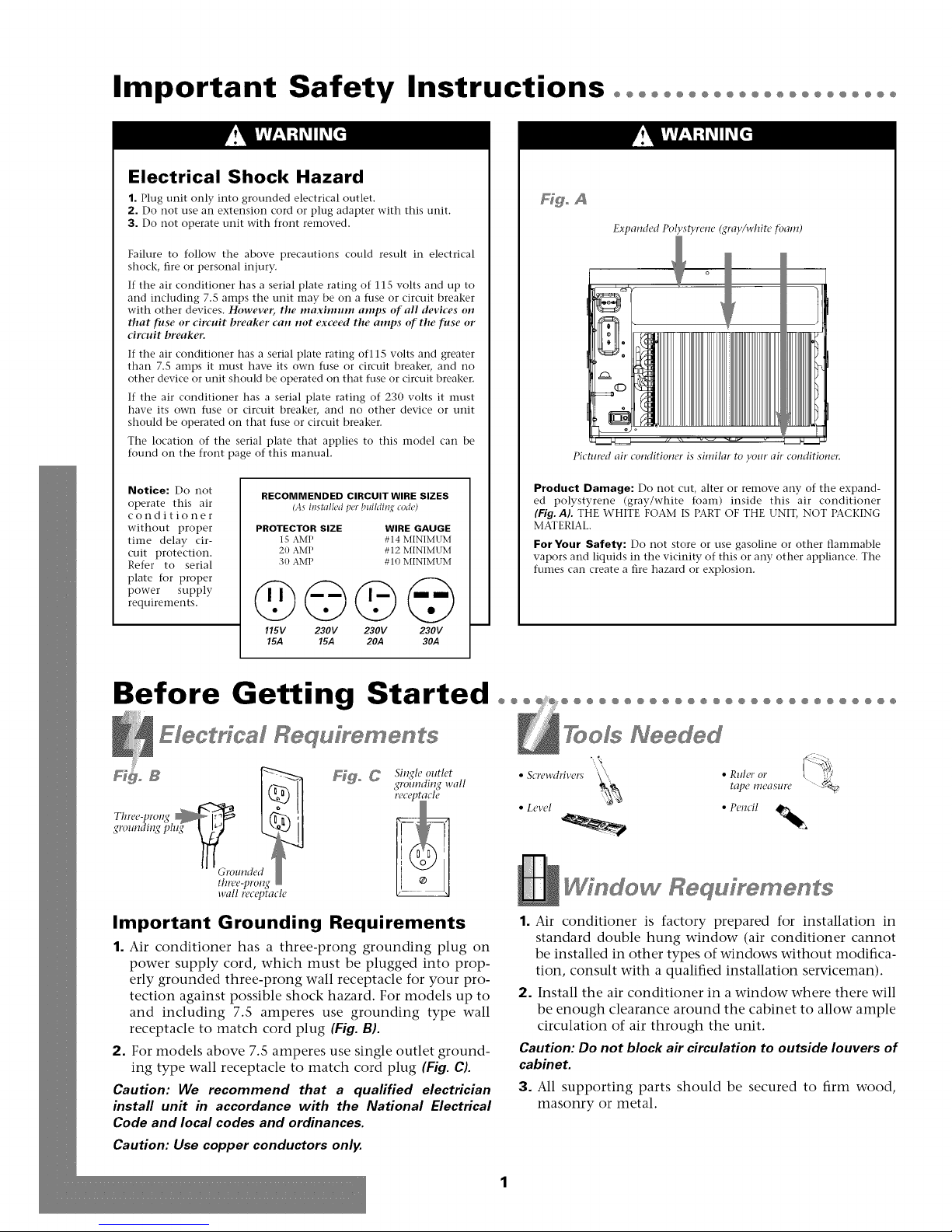
Hgo A
Expanded Polystyrene (gray/white tbam)
o
_ V¸
Pictured air conditioner is similar to your air conditioner
Notice: Do not
operate this air
conditioner
without proper
tiIne delay cir-
cuit protection.
Refer to serial
plate for proper
power supply
requireInents.
RECOMMENDED CIRCUIT WIRE SIZES
(As i_stall_d p_r buildi_g code)
PROTECTOR SIZE WIRE GAUGE
1S AMP #14 MINIMUM
20 AMP #12 MINIMUM
30 AMP #10 MINIMUM
@©©@
115V 230V 230V 230V
15.4 15.4 20A 30A
Product Damage: Do not cut, alter or remove any of the expand-
ed polystyrene (gray/white foam) inside this air conditioner
(Fig. AL THE WHITE FOAM IS PART OF THE UNIT, NOT PACKING
MATERIAL.
For Your Safety: Do not store or use gasoline or other flaInmable
vapors and liquids in the vicinity of this or any other appliance. The
fumes can create a fire hazard or explosion.
Before Getting Started ooo ooooooooooooooooooooooooooo
Electrical Requfyements
_ _ Single outlet • &:rewdrivers • RMer or
Important Grounding Requirements
1. Air conditioner has a three-prong grounding plug on
power supply cord, which must be plugged into prop-
erly grounded three-prong wall receptacle for your pro-
tection against possible shock hazard. For models up to
and including 7.5 amperes use grounding type wall
receptacle to match cord plug (Fig. B).
2. For models above 7.5 amperes use single outlet ground-
ing type wall receptacle to match cord plug (Fig. C).
Caution: We recommend that a qualified electrician
install unit in accordance with the National Electrical
Code and local codes and ordinances.
Caution: Use copper conductors only.
grounding wall tape measure
TooJs Needed
• Level • Pencil
Wfndew Requfrements
1. Air conditioner is factory prepared for installation in
standard double hung window (air conditioner cannot
be installed in other types of windows without modifica-
tion, consult with a qualified installation serviceman).
2. Install the air conditioner in a window where there will
be enough clearance around the cabinet to allow ample
circulation of air through the unit.
Caution: Do not block ak circulation to outside louvers of
cabinet.
3. All supporting parts should be secured to firm wood,
masonry or metal.
Page 3
Installation°°°°°°°°°°°°°°°°°°°°°°°°°°°°°°°°°°°°°°°°°°°°°°°°
do l staH3 fo
Unit & Window Size
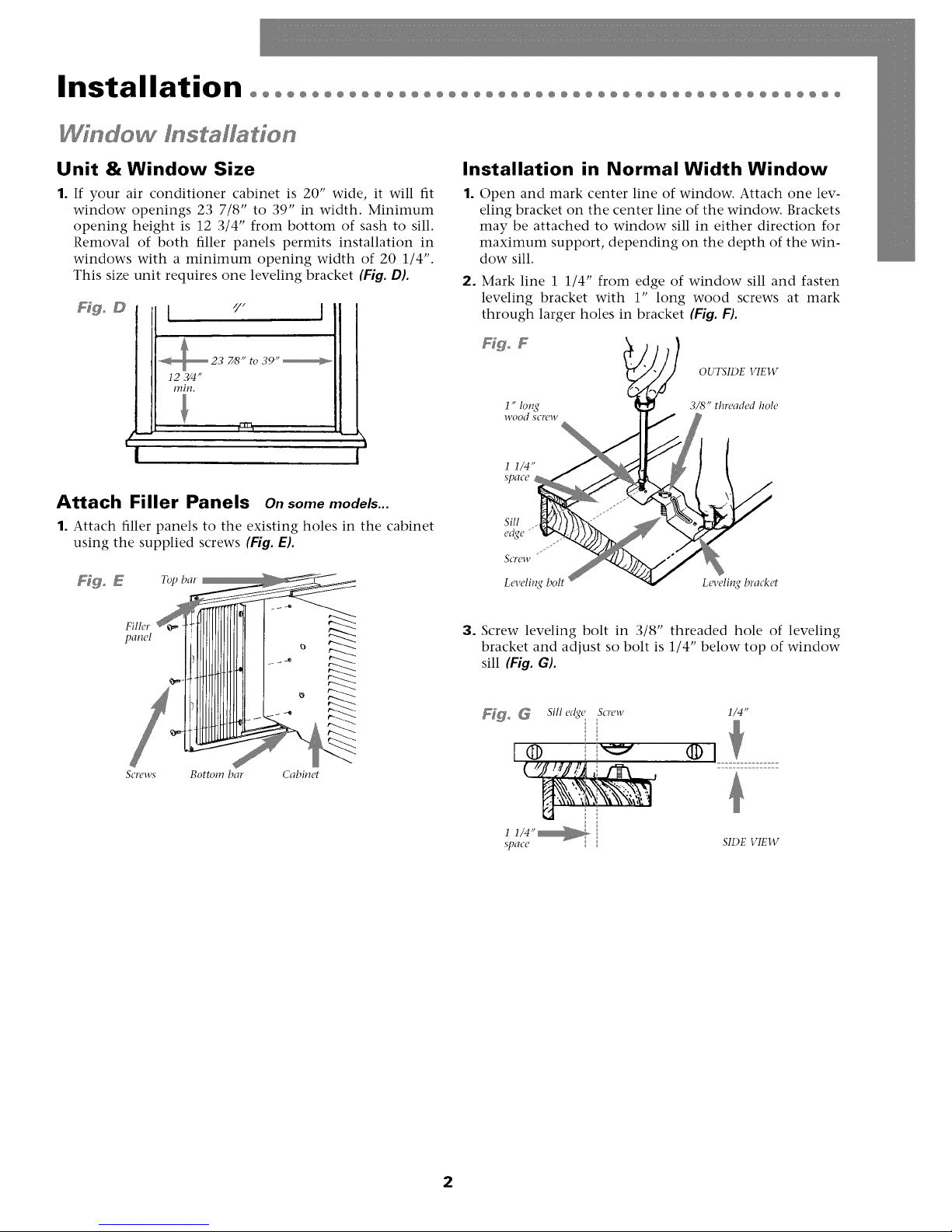
1. If your air conditioner cabinet is 20" wide, it will fit
window openings 23 7/8" to 39" in width. Minimum
opening height is 12 3/4" from bottom of sash to sill.
Removal of both filler panels permits installation in
windows with a minimum opening width of 20 1/4".
This size unit requires one leveling bracket (Fig. D).
Fdgo D "./"
7/8" to 39"
12 ?F4"
rain.
f-- m
, I
Fr_
I I
Attach Filler Panels on somemodels...
1. Attach filler panels to tile existing holes in tile cabinet
using the supplied screws (Fig. E).
Installation in Normal Width Window
Open and mark center line of window. Attach one lev-
eling bracket on the center line of the window. Brackets
may be attached to window sill in either direction for
maximum support, depending on the depth of the win-
dow sill.
2. Mark line 1 1/4" from edge of window sill and fasten
leveling bracket with 1" long wood screws at mark
through larger holes in bracket (Fig. F).
OUTSIDE VIEW
1" 1o_¢ 3/<'_"threaded hole
wood scl'cw
1 1/4"
Sill
SCI'CW
Leveli1_¢ bolt Leveling bracket
Filler
panel
&:rews Bottom bar Cabinet
3. Screw leveling bolt in 3/8" threaded hole of leveling
bracket and adjust so bolt is 1/4" below top of window
sill (Fig. G).
_o _ Sill e_qe &:few
1/4"
® ........
1 1/4"_
SJ)¢ICO
SIDE VIEW
2
Page 4
Installation°°°°°°°°°°°°°°°°°°°°°°°°°°°°°°°°°°°°°°°°°°°°°°°
Window I s aHa io
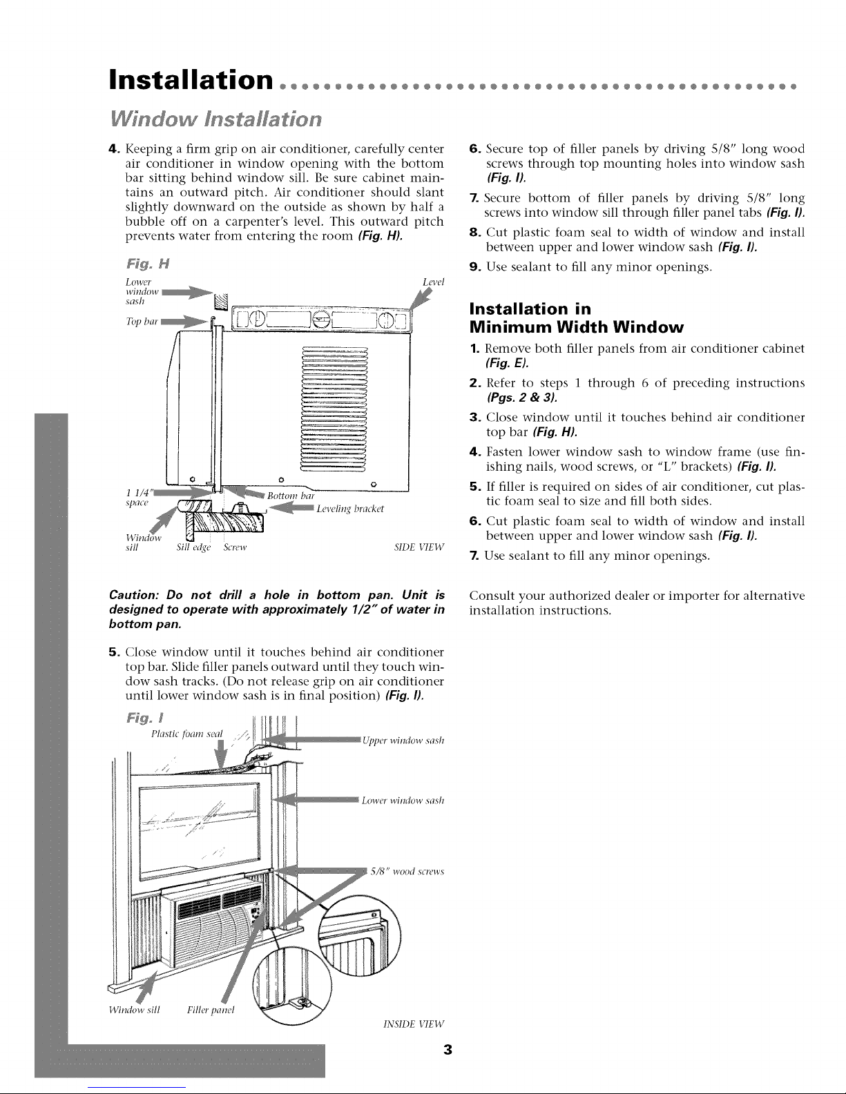
4. Keeping a firm grip on air conditioner, carefully center
air conditioner in window opening with the bottom
bar sitting behind window sill. Be sure cabinet main-
tains an outward pitch. Air conditioner should slant
slightly downward on the outside as shown by half a
bubble off on a carpenter's level. This outward pitch
prevents water from entering the room (Fig. H).
F@o M
Lower
sash
window __
Level
ff
Z_ -_q
I
bar
sill Sill e_¢e Screw SIDE VIEW
Q
6. Secure top of filler panels by driving 5/8" long wood
screws through top mounting holes into window sash
(Fig. I).
7. Secure bottom of filler panels by driving 5/8" long
screws into window sill through filler panel tabs {Fig. I}.
8. Cut plastic foam seal to width of window and install
between upper and lower window sash {Fig. I}.
9. Use sealant to fill any minor openings,
Installation in
Minimum Width Window
1. Remove both filler panels from air conditioner cabinet
(Fig. E).
2. Refer to steps 1 through 6 of preceding instructions
(Pgs. 2 & 3).
3. Close window until it touches behind air conditioner
top bar (Fig. H).
4. Fasten lower window sash to window frame (use fin-
ishing nails, wood screws, or "L" brackets) (Fig. I).
5. If filler is required on sides of air conditioner, cut plas-
tic foam seal to size and fill both sides,
6. Cut plastic foam seal to width of window and install
between upper and lower window sash (Fig. I).
7. Use sealant to fill any minor openings,
Caution: Do not drill a hole in bottom pan. Unit is
designed to operate with approximately 1/2" of water in
bottom pan.
5. Close window until it touches behind air conditioner
top bar, Slide filler panels outward until they touch win-
dow sash tracks, (Do not release grip on air conditioner
until lower window sash is in final position) {Fig. I1.
Figo Z
Plastic fbatn seal
Upper window sash
Lowcr willdow sash
5/8" wood screws
Consult your authorized dealer or importer for alternative
installation instructions,
Window sill Filler panel
INSIDE VIEW
3
Page 5
Operation°°°°°°°°°°°°°°°°°°°
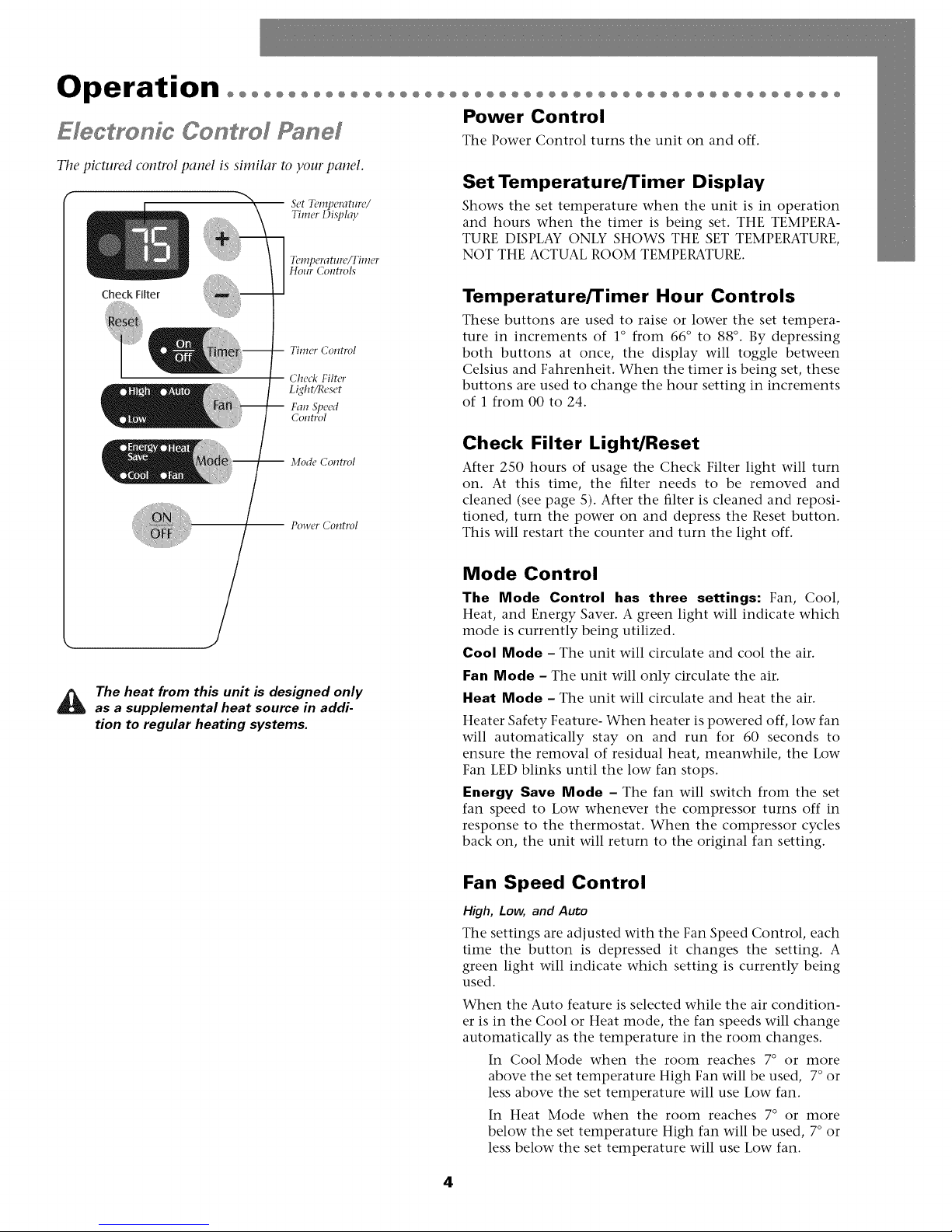
E/ectye /c Ce rel Pa el
Tile pictured control panel is similar to your panel.
°°°°°°°°°°°°°°°°°°°°°°°°°°°°°°°
Power Control
The Power Control turns the unit on and off.
Set Temperature/Timer Display
Shows the set temperature when the unit is in operation
and hours when the timer is being set. THE TEMPERA-
TURE DISPLAY ONLY SHOWS THE SET TEMPERATURE,
NOT THE ACTUAL ROOM TEMPERATURE.
Check Filter
Timer Control
Check Filter
Light/Reset
Fan Speed
Control
Mode Control
-- Power Control
The heat from this unit is designed only
as a supplemental heat source in addi-
tion to regular heating systems.
Temperature/Timer Hour Controls
These buttons are used to raise or lower the set tempera-
ture in increments of 1° from 66 ° to 88 °. By depressing
both buttons at once, the display will toggle between
Celsius and Fahrenheit. When the timer is being set, these
buttons are used to change the hour setting in increments
of 1 from 00 to 24.
Check Filter Light/Reset
After 2S0 hours of usage the Check Filter light will turn
on. At this time, the filter needs to be removed and
cleaned (see page S). After the filter is cleaned and reposi-
tioned, turn the power on and depress the Reset button.
This will restart the counter and turn the light off.
Mode Control
The Mode Control has three settings: Fan, Cool,
Heat, and Energy Saver. A green light will indicate which
mode is currently being utilized.
Cool Mode - The unit will circulate and cool the air.
Fan Mode - The unit will only circulate the air.
Heat Mode - The unit will circulate and heat the air.
Heater Safety Feature- When heater is powered off, low fan
will automatically stay on and run for 60 seconds to
ensure the removal of residual heat, meanwhile, the Low
Fan LED blinks until the low fan stops.
Energy Save Mode - The fan will switch from the set
fan speed to Low whenever the compressor turns off in
response to the thermostat. When the compressor cycles
back on, the unit will return to the original fan setting.
Fan Speed Control
High, Low, and Auto
The settings are adjusted with the Fan Speed Control, each
time the button is depressed it changes the setting. A
green light will indicate which setting is currently being
used.
When the Auto feature is selected while the air condition-
er is in the Cool or Heat mode, the fan speeds will change
automatically as the temperature in the room changes.
In Cool Mode when the room reaches 7 ° or more
above the set temperature High Fan will be used, 7° or
less above the set temperature will use Low fan.
In Heat Mode when the room reaches 7° or more
below the set temperature High fan will be used, 7° or
less below the set temperature will use Low fan.
4
Page 6
Operation°°°°°°°°°°°°°°°°°°°°°°°°°°°°°°°°°°°°°°°°°°°°°°°°°°
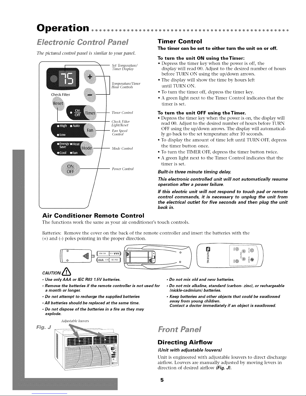
Electmnfc Control Panel
Tile pictured control panel is similar to your panel.
-- Set Temperature/
Timer DisjJlay
Temperature/Timer
Hour Controls
Check FiLter
Timer Control
Check Filter
Light/Reset
Fan Speed
Control
Mode Control
-- Power Control
Timer Control
The timer can be set to either turn the unit on or off.
To turn the unit ON using theTimer:
• Depress the timer key when the power is off, the
display will read 00. Adjust to the desired number of hours
before TURN ON using the up/down arrows.
• The display will show the time by hours left
until TURN ON.
• To turn the timer off, depress the timer key.
• A green light next to the Timer Control indicates that the
timer is set.
To turn the unit OFF using theTimer.
• Depress the timer key when the power is on, the display will
read 00. Adjust to the desired number of hours before TURN
OFF using the up/down arrows. The display will automatical-
ly go back to the set temperature after 10 seconds.
• To display the amount of time left until TURN OFF, depress
the timer button once.
• To turn the TIMER OFF, depress the timer button twice.
• A green light next to the Timer Control indicates that the
timer is set.
Built-in three minute timing delay.
This electronic controlled unff will not automatically resume
operation after a power failure.
ff this electric unit will not respond to touch pad or remote
control commands, it is necessary to unplug the unit from
the electrical outlet for five seconds and then plug the unit
back in.
Air Conditioner Remote Control
The functions work the same as your air conditioner's
Batteries:
Remove the cover on the back of the remote controller and insert the batteries with the
(+) and (-) poles pointing in the proper direction.
o ......j
CAUTION &
• Use onlyAAA or IEC R03 1.SVbatteries.
• Remove the batteries ff the remote controller is not used for
a month or longer,
• Do not attempt to recharge the supplied batteries
• Aft batteries should be replaced at the same time.
• Do not dispose of the batteries in a fire as they may
explode.
Adjustabh, lom'ers
F_go d
i
touch controls.
Q
• Do not mix old and new batteries.
• Do not mix alkaline, standard (carbon- zinc), or rechargeable
(nickle-cadmium) batteries.
• Keep batteries and other objects that could be swaflowed
away from young children.
Contact a doctor immediately if an object is swallowed.
Front Panel
Directing Airflow
(Unit with adjustable louvers)
Unit is engineered with adjustable louvers to direct discharge
airflow. Louvers are manually adjusted by moving levers in
direction of desired airflow {Fig. J).
5
Page 7
Maintenance°°°°°°°°°°°°°°°°°°°°°°°°°°°°°°°°°°°°°°°°°°°°°°
Cleaning Air Filter
EVERY TWO WEEKS: Clean the filter.
1. Turn Master Control to OFF.
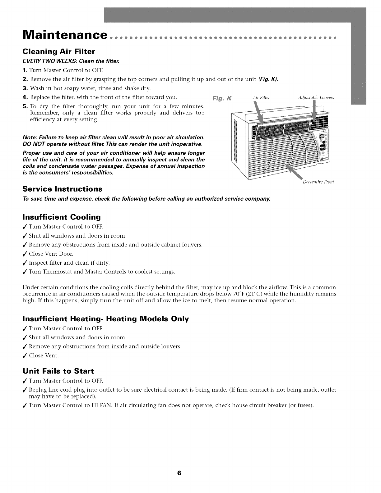
2. Remove the air filter by grasping the top corners and pulling it up and out of the unit (Fig. K).
3. Wash in hot soapy water, rinse and shake dry.
4. Replace the filter, with the front of the filter toward you. Fig° K Air Filter
5. To dry the filter thoroughly, run your unit for a few minutes.
Remember, only a clean filter works properly and delivers top
efficiency at every setting.
Note: Failure to keep air filter clean will result in poor air circulation.
DO NOT operate without filter. This can render the unit inoperative.
Proper use and care of your air conditioner will help ensure longer
life of the unit. It is recommended to annually inspect and clean the
coils and condensate water passages. Expense of annual inspection
is the consumers" responsibilities.
Service Instructions
Tosave time and expense, check the following before calling an authorized service company.
Adjustable Louvers
Decorative Front
Insufficient Cooling
€" Turn Master Control to OFF.
€" Shut all windows and doors in room.
€" Remove any obstructions from inside and outside cabinet louvers.
€" Close Vent Door.
€" Inspect filter and clean if dirty.
€" Turn Thermostat and Master Controls to coolest settings.
Under certain conditions the cooling coils directly behind the filter, may ice up and block the airflow. This is a common
occurrence in air conditioners caused when the outside temperature drops below 70°F (21°C) while the humidity remains
high. If this happens, simply turn the unit off and allow the ice to melt, then resume normal operation.
Insufficient Heating- Heating Models Only
€" Turn Master Control to OFF.
€" Shut all windows and doors in room.
€" Remove any obstructions from inside and outside louvers.
€" Close Vent.
Unit Fails to Start
€" Turn Master Control to OFF.
€" Replug line cord plug into outlet to be sure electrical contact is being made. (If firm contact is not being made, outlet
may have to be replaced).
€" Turn Master Control to HI FAN. If air circulating fan does not operate, check house circuit breaker (or fuses).
6
Page 8
Warrantyoooooooooooooooooooo
O@O@O@O@O@O@O@O@O@O@O@O@O@O@O@O
For Models Installed
in North America - If Service
or Parts are Required
First, make the recommended checks. If it appears that ser-
vice or parts are still required, see your room air condition-
er warranty "How to Obtain Warranty Service or Parts".
For Models Installed
Outside North America
For room air conditioners purchased for use outside North
America, the manufacturer does not extend any warranty
either expressed or implied. Consult your local dealer for
any warranty terms extended by the importer in your
country.
Room Air Conditioner Warranty
(Within the 48 contiguous United States, state of Hawaii,
the District of Columbia, Puerto Rico and Canada)
Full (FiveYear) Parts and Labor Warranty
During the five years after the date of original purchase,
Fedders North America will, through its authorized ser-
vicers and free of charge to the owner or any subsequent
user, repair or replace any parts which are defective in
material or workmanship due to normal use. Ready access
to the air conditioner is the responsibility of the owner.
Note: In the event of any required parts replacement with-
in the period of this warranty, Fedders North America
replacement parts shall be used and will be warranted
only for the period remaining on the original warranty.
Exceptions
The above warranty does not cover failure to function
caused by damage to the unit while in your possession
(other than damage caused by defect or malfunction), or
by its improper installation, or by unreasonable use of the
unit, including without limitation, failure to provide rea-
sonable and necessary maintenance or to follow the writ-
ten Installation and Operating Instructions. If the unit is
put to commercial, business, rental, or other use or appli-
cation other than for consumer use, we make no war-
ranties, express or implied, including but not limited to,
any implied warranty of merchantability or fitness for par-
ticular use or purpose.
THE REMEDIES PROVIDED FOR IN THE ABOVE EXPRESS
WARRANTY ARE THE SOLE AND EXCLUSIVE REMEDIES
THEREFOR, NO OTHER EXPRESS WARRANTIES ARE
MADE. ALL IMPLIED WARRANTIES, INCLUDING BUT NOT
LIMITED TO ANY IMPLIED WARRANTY OF MER-
CHANTABILITY OR FITNESS FOR A PARTICULAR USE OR
PURPOSE, ARE LIMITED IN DURATION TO FIVE YEARS
FROM THE DATE OF ORI(;INAL PURCHASE. IN NO EVENT
SHALL FEDDERS NORTH AMERICA BE LIABLE FOR INDI-
RECT, INCIDENTAL, OR CONSEQUENTIAL DAMAGES,
EVEN IF ADVISED IN ADVANCE OF THE POSSIBILITY OF
SUCH DAMAGES. NO WARRANTIES, EXPRESS OR
IMPLIED, ARE MADE TO ANY BUYER UPON RESALE.
Some states do not allow limitations on how long an
implied warranty lasts or do not allow the exclusion or
limitation of incidental or consequential damages, so the
above limitations or exclusions may not apply to you.
This warranty gives you specific legal rights, and you may
also have other rights which may vary from state to state.
No warranties are made for units sold outside of the above
stated areas. Your distributor or final seller may provide a
warranty on units sold outside of these areas.
How to Obtain
Warranty Service or Parts
Service for your room air conditioner will be provided by
CareCo, a division of the manufacturer with authorized
independent CareCo servicers nationwide.
Note: Before calling for service, carefully read the
Installation and Operating Instructions booklet. Then if
you need service:
1. Call a CareCo authorized servicer and advise them of
model number, serial number, date of purchase and
nature of complaint. Service will be provided during
normal working hours. Contact your dealer for the
name of an authorized servicer if unknown to you.
2. If your dealer is unable to give you the name of a ser-
vicer or if you need other assistance, call the following
toll-free number for the name of an authorized servicer
or authorized parts distributor:
1-866-MAYTAG 1
or you may write:
CareCo, Service Department
415 W. Wabash Ave., RO. Box 200
Effingham, IL 62401
Proof of Purchase Date
It is the responsibility of the consumer to establish the
original purchase date for warranty purposes. We recom-
mend that a bill of sale, cancelled check, or some other
appropriate payment record be kept for that purpose.
7
Page 9

Instrucciones importantes de seguridadoooooooooo
Peligro de descarga el6ctrica
1. Enehufe la unidad en till tonlaeorriente con eonexi6n a tierra.
2. No use un cable de extensi6n ni un adaptador de enchufe con este
aparato.
3. No 1o haga funcionar sin la cubierta delantera.
El no seguir las precauciones enumeradas anteriormente podria
causar descargas elOctricas, incendio o lesiones personales,
Si el acondicionador de aim trae en la placa tma clasificaci6n de 115
voltios y hasta 7,S amperios inclusive, la unidad puede ir conectada
al mismo fusible o cortacircuitos junto con otros aparatos, Sin
embargo, el mdximo amperaje de todos los aparatos conectados a
la vez a ese fusible o cortacil_'uitos no debe ser mayor que la capaci-
dad (amperios) de dicho fusible o cortacircuitos.
Si el acondidonador de aim trae en la placa una clasificad6n de 115
voltios v re,is de 7.5 amperios, entonces debe ir conectado a su pro-
pio fusible o cortadrcuitos y ningfn otro aparato o unidad se podrfi
conectar a dicho fusible o cortadrcuitos.
Si el acondicionador de aire trae en la placa una clasificaci6n de 230
voltios, entonces debera ir conectado a su propio fusible o cortacir-
cuitos y ningfin otro aparato o unidad se podra conectar a dicho
fusible o cortacircuitos.
La ubicaci6n de la placa con la serie correspondiente a este modelo
se encuentra en la pfigina del frente de este manual.
Aviso: No haga tim-
cionar estre aire acondi-
cionado sin un circuito
temporizador que
brinde la protecci6n
adecuada. En la placa
de identificaci6n apare-
cen los requisitos cor-
rectos de alimentaci6n.
TAMAI_IOS RECOMENDADOS PARA LOS
ALAMBRES DEL CIRCUITO
(h_stalado s(',_thl los I_'ghmle_tos de clmsmwcil_)
TAMAI_O DEL CALIBRE DEL
PROTECTOR ALAMBRE
15 AMP #14 MINIMO
20 AMP #12 MINIMO
O)AMP #10MINIMO
Hgo A
Poliestireno expandido (Estmma gris/bhmca)
o
o
El aim acondicionado tle la foto es similar al s_lyo.
Dafio al producto: No corte, altere o retire ningdn pedazo de poli-
estireno expandido (espuma gris/blanca) que se encuentre dentro del
acondicionador de aim (Fig. A). EL POLIESTIRENO EXPANDIDO
FORMA PARTEDE LAUNIDAD, NO ES MATERIAL DE EMBALAJE,
Para su seguridad: No ahnacene ni utilice gasolina u otros vapores
y liquidos inflamables cerca de este artefacto o de cualquier otro arte-
facto, Los vapores pueden provocar un incendio o una explosi6n,
@©©@
115V 230V 230V 230V
15A 15A 20A 30A
Antes de empezaroooooooooo ooooooooooooooooooooooooooo
Req dstos para fa electdcos
Recept&:ulo mm'al
con salida simple
de tmesta a tierra
Requistos importantes
para la conexi6n a tierra
1. E1 equipo de aire acondicionado tiene en el cord6n de
corriente un enchufe a tierra de tres puntas, el cual debe
ser introducido en un tomacorriente de tres puntas
debidamente conectado a tierra para protecci6n contra
posibles descargas el6ctricos. Para modelos de hasta 7.S
amperios utilice un tipo de tomacorriente con conexi6n
a tierra, adecuado para el enchufe del equipo (Fig. B).
2. Para modelos de mils de 7.S amperios, utilice un tomacor-
riente con conexi6n a tierra para un solo enchufe (Fig.eL
Precaucion: Recomendamos que un electricista calificado
instale la unidad de acuerdo alas normas electicas
nacionales y las normas y regulaciones locales.
Precaucion: Utifice solamente conductores de cobre.
8
Herramfentas necesadas
• l)estomillador('s \'\-- • Regla
Req ds[tos de la ventana
1. E1acondicionador de aire se prepara en la ffibrica para
una instalaci6n estfindar en ventanas de guillotina (los
acondicionadores de aire no pueden instalarse en otros
tipos de ventanas sin modificarlas -- para hacer esto
hay que consultar a un instalador calificado).
2. Instale el aire acondicionado en una ventana con espa-
cio suficiente alrededor del gabinete, esto para permitir
que haya bastante circulaci6n del aire a trav4s de la
unidad.
Precauci6n: No bloquee la circulacidn del aire de las rejil-
las exteriores del gabinete.
3. Todas las piezas de apoyo deberfin asegurarse a madera,
material de albaflileria o metal firme.
Page 10

Instalaci6n oooooooooooooooooooooooooooooooooooooooooooooooo
fnstafacion en fa ventana
Tama_o de la ventana y de la unidad
1. Si el gabinete de su aire acondicionado mide 20" de
ancho, entonces se ajustarfi a aberturas de 23 7/8" hasta
39" de ancho. La altura minima de la abertura es 12
3/4" desde la parte inferior del marco hasta el alf4izar.
Si la abertura de la ventana donde se va a instalar tiene
un ancho minimo de 20 1/4" quite los paneles de rel-
leno. Las unidades de este tamafio requieren el uso de
un soporte nivelador (Fig. D).
Fdgo D ¢"
23 7/8" to 39"
12 2/4"
min.
iI
I I
Instale los paneles de Ilenado
En algunos modelos...
1. Conecte los paneles de llenado a los orificios existentes
en el gabinete utilizando los tornillos suministrados
(Fig. E).
Instalaci6n en un ventana
de ancho normal
1. Abra la ventana y marque la linea central. Acople un
soporte nivelador en la linea central de la ventana. Los
soportes pueden acoplarse a la repisa de la ventana en
cualquier direcci6n para mfiximo apoyo, dependiendo
de la profundidad de la repisa de la ventana.
2. Marque una linea a 1 1/4" del borde de la repisa de la
ventana y fije el soporte nivelador con tornillos de 1"
para madera en la marca a trav4s de los agujeros
grandes en el soporte (Fig. F).
Fdgo F
VISTA EXTERIOR
Tornillos de 1" Agujem roscado
&l_amci6n
de 1 1/4"
Bordc
de la /
rq_isa //
Tornillo
Perno nivelador Soporte nivelador
Panel
tle
llellado
Tornillos Barra inferior Gabim'te
o
3. Enrosque el perno nivelador en el orificio roscado de
3/8" del soporte nivelador y ajOstelo de manera que el
perno se encuentre a 1/4" debajo del dintel de la ven-
tana (Fig. G).
_o _ Borde de Tornillo 1/4 pu(,z,ada
la r_Tisa
WSTA LATERAL
9
Page 11

Instalaci6n oooooooooooooooooooooooooooooooooooooooooooooooo
Insta[acion en fa ventana
4. Centre el acondicionador de aire en la abertura de la
ventana con la barra inferior asentada detrfis del quicio
de la ventana. Cerci6rese de que el gabinete mantenga
una inclinaci6n hacia afuera. E1 acondicionador de aire
deberfi inclinarse ligeramente hacia el exterior usando la
indicaci6n de un nivel de carpintero. Dicha inclinaci6n
evitarfi que el agua entre en la habitaci6n (Fig. H).
Nivel
interior Borde de Tornillo WSZ4 LATERAL
Precaucion: No perfore un orificio en la bandeja inferior.
El dise_o de la unidad permite que funcione con aproxi-
madamente 1/2 pulgada de agua en la bandeja inferior.
la repisa
5. Cerrar la ventana hasta que toque la barra superior por
detrfis del acondicionador de aire. Deslizar los paneles
de relleno hacia afuera hasta que toquen las guias del
bastidor de la ventana. (No soltar el acondicion-ador de
aire hasta que el bastidor inferior de la ventana est4 en
su posici6n final) (Fig. I1.
Fig° Z
Sellante de esl)onja
pldstica Bastidor superior
dc la "V¢lltalqa
6. Fijar la parte superior de los paneles de llenado inser-
tando tornillos para madera de S/8 de pulgada de largo
por los huecos de montaje en el bastidor inferior de la
ventana (Fig. 11.
7. Fijar la parte inferior de los paneles de llenado insertan-
do tornillos para madera de S/8 de pulgada de largo en
el quicio de la ventana a trav_s de las presillas del panel
de relleno (Fig. 11.
8. Cortar el sellador de espuma de plfistico del mismo
ancho de la ventana e instalario entre el bastidor supe-
rior y el bastidor inferior de la ventana (Fig. 11.
9. Utilice material de sellar para rellenar pequef]as aberturas.
Instalaci6n en una ventana
de ancho minimo
1. Retirar ambos paneles de llenado del gabinete del
acondicionador de aire (Fig. El.
2. Consultar los pasos 1 a 6 de las instrucciones prece-
dentes (Pgs. 8 & 9).
3. Cerrar la ventana hasta que toque la barra superior pot
detrfis de la unidad (Fig. H).
4. Ajustar el bastidor inferior de la ventana al marco de la
ventana (usar clavos de acabado, tornillos de madera o
soportes en "L') (Fig.11.
5. Si se necesita el llenado a ambos lados del acondi-
cionador de aire, cortar un sellador de espuma de plfis-
tico del mismo tamaf]o y llenar ambos lados (Fig. 11.
6. Cortar un sellador de espuma de plfistico del mismo
ancho de la ventana e instalario entre el bastidor supe-
rior y el bastidor inferior de la ventana (Fig. 11.
7. Utilice material de sellar para rellenar pequef]as aberturas.
Consultar al distribuidor o importador autorizado en caso
de necesitar instrucciones para otro tipo de instalaci6n.
Alf_izar interior Panel de
llenado
Tornillo para
madera de 5/8"
• 7
ISTA IN TERIOR
10
Page 12

Funcionamiento oooooooo
°°°°°0°°°°00°°°°00°°°°00°°°°00°°°°
Control de Alimentaci6n
Pa el de control elec rd Jco
Este bot6n pone en marcha y apaga el acondicionador de aire.
Indicador de Temperatura de Ajuste/Temporizador
E1indicador muestra la temperatura de ajuste cuando el acondi-
cionador de aire estfi en funcionamiento y las horas cuando se ha
activado el temporizador. EL INDICADOR DE LATEMPERATURA
SOLAMENTE MUESTRA LATEMPERATURA DE AJUSTE, NO LA
TEMPERATURA AMBIENTE REAL.
Control de laTemperatura/Temporizador
Check Filter
Estos botones se usan para aumentar o reducir la temperatura de
ajuste en incrementos de 1 °, entre 66°F hasta 88°E Si se oprimen
simultfineamente ambos botones, el indicador digital cambiarfi
entre grados Celsius y Fahrenheit. Cuando se activa el tempo-
rizador, estos botones son usados para cambiar el ajuste de la hora
en incrementos de 1, entre O0 hasta 24.
Control tie
velocidad tie
ventilador
Selector de IVIodo
Una luz verde indicarfi el modo que estfi siendo utilizado.
Mode "Cool" (Frio) - E1acondicionador de aire circula y enfria
el aire.
Modo "Heat" (Calor) - E1 acondicionador de aire circula y
calienta el aire.
Caracteristica de Seguridad del Calentador - Cuando el calenta-
dor estfi apagado, el ventilador de baja velocidad se activarfi y
funcionarfi durante 60 segundos para asegurar la eliminaci6n de
algfin calor residual, a la vez que el diodo LED 'Low Fan' (venti-
lador de baja velocidad) destella hasta que se detenga el venti-
lador de baja velocidad.
Modo 'Fan" (Ventilador) - E1acondicionador de aire solamente
harfi circular el aire.
Modo 'Energy Save" (Ahorro de Energia) -
(El modo de ahorro de energia estfi disef]ado para funcionar sola-
mente con el modo 'Cool'). E1ventilador cambiarfi de la veloci-
dad de ajuste a velocidad baja cuando el compresor sea apagado
El calor proveniente de este
acondicionador de aire ha sido
disefiado solamente como una
fuente de calor suplementario
y no sustituye a los sistemas
de calefaccibn regulares.
por el termostato. Cuando el compresor se activa nuevamente, el
ventilador volverfi al ajuste original. La velocidad del ventilador
cambia automfiticamente segfin cambie la temperatura en la
habitaci6n.
Control de la Velocidad del Ventilador - Alta,
Baja y Automfitica
E1 ajuste de la velocidad del ventilador se cambia cada vez que se
oprime el bot6n de control de velocidad del ventilador. Una luz
verde indicarfi el ajuste que se ha seleccionado.
Cuando se selecciona 'Auto' (Automfitico) y el acondicionador de
aire estfi en el modo 'Cool' o 'Heat', la velocidad del ventilador cam-
biarfi automfiticamente a medida que cambie la temperatura en la
habitaci6n. En el modo 'Cool', cuando la habitaci6n llega a 7° o
mils, sobre la temperatura de ajuste, se usa 'High Fan' (Alta
Velocidad), cuando la temperatura en la habitaci6n es de 7 ° o
menos, sobre la temperatura de ajuste, se usa 'Low Fan' (Velocidad
Baja). En el modo 'Heat' cuando la habitaci6n alcanza 7° o mils,
bajo la temperatura de ajuste, se usa 'High Fan', cuando la
habitaci6n alcance 7 ° o menos, bajo la temperatura de ajuste, se usa
'Low Fan'.
11
Page 13

FuncionamientOoooooooooooooooooooooooooooooooooooooooooo
Panel de control elec ydnfco
Control del Temporizador (El temporizador puede ser ajustado ya seapara encender o apagar el acondicionador de aire.)
Para PONER EN MARCHA automfiticamente el acondi- Para APAGAR automfiticamente el acondicionador de aire usan-
cionador de aire usando el modo 'Timer':
1. Oprima el botdn 'Timer' cuando la alimentacidn 1.
el6ctrica est6 desconectada. E1 indicador mostrarfi
00. Ajuste el indicador para que muestre el nfmero
de horas que desea que transcurran antes de la
PUESTA EN MARCHA, usando las flechas de ajuste
'Temperature/Timer' (Temperatura/Temporizador).
2. E1 indicador mostrarfi la cantidad de horas que fal-
tan para la PUESTA EN MARCHA. 2.
3. Para salir del modo 'Timer', optima el bot6n 'Timer'.
4. Una luz verde situada junto al bot6n 'Timer' se ilu- 3.
minarfi para indicar que el 'Timer' estfi activado.
Luz de verificaci6n de filtro/
reinicializar
Despu_s de 2S0 horas de uso se encenderfi la luz de verificaci6n de filtro. Cuando esto sucede, debe quitarse y limpiarse
el filtro (vet pfigina 12). Despu_s de limpiar y volver a colocar el filtro, presione el bot6n Reset (Reinicializar). Este bot6n
volverfi a cero el contador y apagarfi la luz.
do el modo 'Timer':
Oprima el botdn 'Timer' cuando la alimentacidn el_ctrica
est_ conectada. E1 indicador mostrarfi 00. Ajuste el indicador
para que muestre el nfimero de horas que desea que tran-
scurran antes de que se APAGUE usando las flechas de ajuste
'Temperature/Timer' (Temperatura/Temporizador). (Despu_s
de 10 segundos, el indicador volverfi automfiticamente a la
temperatura de ajuste.)
Para vet la cantidad de horas que faltan para que se APAGUE
el acondicionador de aire, oprima una vez el bot6n 'Timer'.
Para salir del modo 'Timer', optima el bot6n 'Timer' dos
veces.
4.
Una luz verde situada junto al bot6n 'Timer' se iluminarfi
para indicar que el 'Timer' estfi activado.
Mecanismo de retraso de tres minutos incorporado
Este aparato controlado electronicamente reanudara su operacion despues de la intetrupci6n del ser-
vicio electrico.
Si este aparato electronico no responde a los mandos del control remoto o cojinete tactil, sera
necesario desenchufarlo cinco segundos y luego volver a enchufar.
Contyol Remote de Acondidoy_ado_ de A_re
Las funciones trabajan igual que los controles manuales de su acondicionador de aire.
Pilas:
Retire al tapa en la parte trasera del control remoto e inserte las baterias con los polos (+) y (-) en la direc-
ci6n correcta.
o
I°
ATENCION
• Use solamente pilas AAA o IEC R03 de 1,5V
• Retire las pilas si el control remoto no va a ser usado
durante un mes o mas.
• No intente recargar las pilas suministradas.
• Todas las pilas deben ser reemplazadas a un mismo tiempo.
• No incinere las pilas pues pueden explotar.
• No mezcle pilas nuevas con pilas viejas.
• No mezc/e pi/as a/ca/inas, standard (carbon-zinc), con pi/as
recargables (nickel-cadium).
• Mantenga fuera del alcance de los ni_os peque_os las pilas
y otros articulos que puedan ser tragados. Pongase inmedi-
atamente en contacto con un medico si un ni_o peque_o se
traga un objeto.
12
Page 14

FuncionamientOoooooooooooooooooooooooooooooooooooooooooo
Panel frontal
Fig° J
Persianas a]ustables
Orientaci6n de la
corriente de aire
(Unidad con rejilla directriz ajustable)
La unidad viene equipada con rejillas
directrices ajustables que permiten diri-
gir la descarga de la corriente de aire. Las
rejillas pueden ajustarse manualmente
moviendo las palancas en la direccidn
deseada (Fig. J).
MantenimientOoooooooooooo
Limpieza del filtro de aire
CADA DOS SEMANAS: Limpie el filtro.
1. Ponga el control maestro en posici6n apagado.
2. Para retirar el filtro de aire, suj_telo de las esquinas supe-
riores y remu_valo hacia arriba y hacia afuera (Fig. K).
_i_ _ Filtros de aire Persianas ajustables
°°°°°@°°°°°°°@°°°°°°°@°°°°°°°@0
Servicio
Para ahorrar tiempo y gastos, revise Io siguiente antes de
Ilamar a la empresa de servicio autorizado.
Enfriamiento insuficiente
€" Ponga el control maestro en posici6n apagado.
€" Cierre todas las ventanas y puertas de la habitaci6n.
€" Retire todas las obstrucciones de las rejillas interna
y externa del gabinete de la unidad.
€" Puerta de ventilaci6n (disponible en la mayoria de los
modelos).
€" Inspeccione el filtro y limpielo si estfi sucio.
€" Ponga el termostato y el control maestro en los valores
mils frios.
3. Lfivelo con agua caliente enjabonada, enjufiguelo, sacfi-
dalo y s6quelo.
4. A1ponerlo de nuevo en su lugar, asegfirese que el lado
frontal quede mirando a usted.
5. Para secar bien el filtro, haga funcionar la unidad
durante unos minutos. Recuerde, que s61o un filtro
limpio harfi funcionar su unidad correctamente y darfi
siempre el servicio mils eficiente.
Advertencia: El no mantener limpio el filtro podria resul-
tar en baja circulacion del aire. NUNCA haga funcionar la
unidad sin el filtro ya que puede quedar inutilizable.
El uso y mantenimiento adecuados del acondicionador
de air prolongara la vida util de la unidad. Se recomienda
inspeccionar y limpiar anualmente el serpentin y los
pasajes para agua de condensacion. El cliente debera
cubrir los gastos de inspeccion anua/.
Bajo ciertas condiciones, los serpentines de enfriamiento
ubicados directamente detrfis del filtro podrian congelarse
y bloquear el pasaje del aire. Esto ocurre por lo general en
acondicionadores de aire cuando la temperatura externa
desciende a menos de 21°C (70°F) mientras que la
humedad se mantiene elevada. Si esto ocurre, simple-
mente apague la unidad y deje que se derrita el hielo antes
de reanudar el funcionamiento normal.
Si la
v"
v"
v"
unidad no se enciende
Ponga el control maestro en posici6n apagado.
Vuelva a enchufar el enchufe del cord6n en el tomacor-
riente para cerciorarse de que se estfi haciendo el con-
tacto el_ctrico. (Si no se verifica un contacto firme serfi
necesario cambiar el tomacorriente).
Ponga el control maestro en ventilador alto. Si el venti-
lador de circulaci6n de aire no funciona, verifique los
disyuntores o fusibles de la residencia.
13
Page 15

Garantiaooooooooooooooooooooo
0000000000000000000000000000000
Para modelos instalados en
Norteam6rica - En caso de necesidad
de servicio o piezas
Haga primer() las verificaciones recomendadas. En caso
de necesitarse servicio o piezas, consulte en la garantia de
su acondicionador de aire en la secci6n "C6mo obtener
servicio o piezas de garantia'.
Para modelos instalados
fuera de Norteam_rica
Para aires acondicionados comprados para uso fuera de
Norteam_rica el fabricante no otorgarfi ninguna garantia
implicita o explicita. Consulte a su distribuidor autoriza-
do sobre las condiciones de la garantia extendida pot el
importador de los equipos de su pais.
Garantia del acondicionador de aire
(Dentro de los 48 estados contiguos de los Estados
Unidos, estado de Hawai, Distrito de Columbia, Puerto
Rico y Canada)
Garantia para todas las piezas (cinco a_os)
y mano de obra
A partir de la fecha de compra y durante un periodo de
cinco aflos, Fedders North America, mediante sus esta-
ciones de servicio autorizadas, repararfi o reemplazarfi sin
costo alguno para el propietario o usuario, cualquier pieza
que presente dafios de material o mano de obra derivados
del uso normal del producto. Es responsabilidad del propi-
etario facilitar el acceso al acondicionador de aire para
realizar los servicios de reparaci6n.
Nota: En caso de que se requiera reemplazar una pieza
mientras la garantia esta vigente, se utilizaran los
repuestos de Fedders North America los cuales contin-
uaran en vignecia solamente durante el resto del periodo
de garantia de la unidad.
Excepciones
La garantia antes indicada no cubre las fallas de fun-
cionamiento causadas por daflos que sufra la unidad
mientras _sta est_ en posesi6n del usuario (excluyendo los
daflos causados por defecto o funcionamiento defectu-
oso), o por la instalaci6n incorrecta, o la utilizaci6n inde-
bida de la unidad, incluyendo pero sin limitarse a ello, la
negligencia en proporcionar el mantenimiento necesario
y adecuado o en seguir las "instrucciones de Instalaci6n y
Uso" indicadas por escrito. En caso de utilizarse la unidad
para fines comerciales, de negocios, de arriendo u otto uso
o aplicaci0n que no sea el uso del consumidor, no otorg-
amos garantia explicita ni implicita, incluyendo, pero sin
limitarse a, toda garantia implicita de negociabilidad o
idoneidad para un uso o finalidad particular.
LAS SOLUCIONES EXPUESTAS EN LA GARANTIA ANTERI-
OR SON EXCLUSIVAS. SE RECHAZA CUALQUIER OTRA
GARANTIA YA SEA EXPRESA 0 IMPLICITA, INCLUYENDO,
PERO SIN LIMITARSE A ELL(), TODAS LAS GARANTIAS DE
COMERCIABILIDAD 0 IDONEIDAD PARA UN FIN EN PAR-
TICULAR DURANTE CINCO ANOS A PARTIR DE LA FECHA
DE COMPRA. BAJO NINGUNA CIRCUNSTANCIA FEDDERS
NORTH AMERICA SE HARA RESPONSABLE POR NINGUN
DAI_O DIRECT(), INDIRECT() 0 CONSECUENCIAL, SIN
IMPORTAR LA CAUSA DE LA ACCION, AUN CUANDO
FEDDERS NORTH AMERICA HAYA SIDO ADVERTIDO CON
ANTERIORIDAD DE LA POSIBILIDAD DE DICHOS DAN()&
NO SE OFRECE NINGUNA GARANTIA EXPRESA 0 IMPLICI-
TA A COMPRADORES DESPUES DE LA REVENTA.
Algunos estados no permiten limitar el tiempo de
duraci6n de una garantia implicita ni permiten excluir ni
limitar los daflos incidentales o emergentes, de modo que
las limitaciones o exclusiones antes indicadas podrian no
aplicarse en su caso. Esta garantia le otorga derechos
legales especificos. Usted podria tener tambi_n otros dere-
chos que pueden variar de estado a estado.
No se ofrecen garantias para las unidades vendidas fuera
de las fireas antes indicadas. Su distribuidor o vendedor
final podria proporcionar una garantia para las unidades
vendidas fuera de estas fireas.
C6rno obtener servicio
o piezas de garantia
E1 servicio para su acondicionador de aire serfi provisto por
CareCo, una divisi6n del fabricante con estaciones de ser-
vicio independientes CareCo autorizadas en todo el pais.
Nota: Antes de solicitar servicio, lea cuidadosamente el
folleto de "lnstrucciones de Instalacion y Uso" Luego, si
necesita servicio:
1. Llame a un taller de servicio autorizado CareCo y
suministreles el nfimero de modelo, nfimero de serie, la
fecha de compra y la naturaleza del problema. E1 servicio
se prestarfi durante horas normales de trabajo.
Comuniquese con su distribuidor para obtener recomen-
daciones sobre una estaci6nde servicio autorizada.
2. Si su distribuidor no puede proporcionarle el nombre
de un taller de servicio o si necesita otro tipo de asis-
tencia, llame al siguiente nfimero gratis para obtener el
nombre de un taller de servicio autorizado o dis-
tribuidor de piezas autorizado:
1-866-MAYTAG 1
o escriba al:
Departamente de Servicio de CareCo
415 W. Wabash Ave., RO. Box 200
Effingham, IL 62401 EE. UU.
Prueba de la fecha de compra
E1 establecimiento de la fecha de compra original para
efectos de la garantla es responsabilidad del consumidor.
Recomendamos mantener la factura de compra, el cheque
cancelado o algfin otto registro de pago apropiado para
dicho efecto.
14
Page 16

Directives de s6curit6 importanteSooooooooooooooooo
Danger de choc 61ectrique
1. N'enficher le climatiseur que dans une prise _lectrique Inise _ la
terre.
2. Ne passe servir d'une rallonge ou d'un adaptateur avec cet
appareil.
3. Ne pas faire marcher le climatiseur si le panneau avant a _t_ retire.
Suivre les prOcautions indiquOes ci-dessus pour Oviter tout risque
d'Olectrocution, d'incendie ou de Dsion corporelle.
Si la plaque de sOrie du cliInatiseur indique une tension nominale de
11S volts et une intensitO en amperes nominale allant jusqu' fl 7,SA,
l'appareil peut Otre branchO sur le m_me fusible ou disjoncteur que
d'autres appareils. Toute_,is, I'intensit_ maximale en amperes de
I'ensemble des appareils branch_s sur ce fusible ou disjoncteur ne
doit pas d_passer celle du fusible ou du disjoncteur.
Si la plaque de sOrie du climatiseur indique une tension en volts
noIninale de 115 volts et une intensitO en amperes nominale
supOrieure 5 7,5 A, l'appareil dolt _tre dot_ de son propre fusible ou
disjoncteur et aucun autre appareil ne dolt y _tre branchO.
Si la plaque de sOrie du climatiseur indique une tension en volts
nominale de 230 volts, l'appareil dolt Otre dot_ de son propre fusible
ou disjoncteur et aucun autre appareil ne doit y Otre branchO.
L'emplacement de la plaque signal_tique applicable ,5 ce module est
indiquO sur la page couverture du present inanuel.
Avis: Ne pas utiliser
le climatiseur sans la
protection d'un circuit
de temporisation. Se
reporter ,5 la plaque sig-
nalOtique pour toute
indication de puissance
exig_e.
CALIBRES DE FIL RECOMMANDES
gSelo_tlO_stalhOio_stipttl&
par h"cod_"d_,dOIlSOlldthlll)
PROTECTION CALIBRE
DU CIRCUIT DE FIL
1S A N°14 MINIMUM
20 A N°12 MINIMUM
30 A N°10 MINIMUM
Fifo A
Polystyd, ne expansd (Mousse _(rise/bhmche)
o
L'appareil illustrd est semblable h votre clintatiseur
Endommagement du produit: Ne pas couper, altOrer ou retirer le
polystyrene expansO (mousse grise/blanche) se trouvant fl l'intOrieur
du climatiseur (Fig.A). LE STYROFOAM N'EST PASUN EMBALLAGE,
IL FAIT PARTIEINTI_GRALEDE L'APPAREIL.
Pour votre s4curit4: Ne pas stocker ou utiliser de l'essence ou toute
autre vapeur ou liquide inflammable ,5 proximitO de cet appareil ou
de tout autre. Les Omanations peuvent crOer un risque d'incendie ou
d'explosion.
@©©@
115V 230V 230V 230V
15A 15A 20A 30A
Pr6paratifSo°oo°oo°oo°oo°oo°oo
Exigences electdque
Fiche h trois
l.ocl,esavec" _ _)
N_o _ _ Nd_o C PriseuniquemUraleavec
terre
Prise murale h trois
bl'OC[lt'S f?ldeC telTe
Importantes exigences de mise _ la terre
1. E1 climatiseur est pourvu d'une fiche de mise fi la terre fi
trois broches sur le cordon 41ectrique. Cette fiche doit
htre branchhe sur une prise murale fi trois broches
dhment mise fi la terre afin de prot4ger contre
d'4ventuels risques de chocs. Pour les modules allant
jusqu'au 7.5 A inclusivement, utiliser une prise murale
de type mise it la terre correspondant it la fiche (Fig. B).
2. Pour les modules de plus de 7.5 A, utiliser une prise
murale simple de mise it la terre correspondant it la fiche
(Fig. C).
Attention: Nous recommandons que I'appareil soit monte
par un electricien competent conformement au Code elec-
trique national ainsi qu'au code et reglements Iocaux.
Attention: Utiliser uniquement des conducteurs en cuivre.
teFFe
°°°°°°°°°°°°°°°°°°°°°°°°°° °
Oudls 6¢essa >es
Spdcfffcatfons de la fen tre
1. Le climatiseur est prhpar4 fi l'usine en vue d'un mon-
tage dans des fenhtres fi guillotine standard (le clima-
tiseur ne peut pas htre month darts d'autres types de
fenhtre sans modification, pri_re de consulter un tech-
nicien de montage comp4tent).
2. Faire la pose du climatiseur darts une fenhtre o6 il y a
un dhgagement suffisant pour assurer un apport d'air
abondant fi l'appareil.
Mise en garde: Ne pas emp6cher I'air de circuler vers
I'exterieur des Iouvres du coffret.
3. Toutes les pi_ces de soutien doivent htre fix4es solide-
merit fi des surfaces fermes en bois, magonnerie ou
m4tal.
15
Page 17

Montage°°°°°°°°°°°°°°°°°°°°°°°°°°°°°°°°°°°°°°°°°°°°°°°°°°°
/ s affaffo d3 s fe 8 re
Dimensions de I'appareil
et de la fen_tre
1. Si le boiter du climatiseur est d'une largeur de 20 po, il
convient aux fen_tres dont l'ouverture est d'une largeur
de 23 7/8 _ 39 po. La hauteur d'ouverture minimum est
de 12 3/4 po /_ partir du bas du chassis /_ l'appui. Le
retrait des deux panneaux de remplissage permet la
pose dans des fen_tres dont l'ouverture est d'une
largeur minimum de 20 1/4 po. Cette taille de clima-
tiseur requiert une fixation de nivellement (Fig. D).
F_o D
12 3/4"
min.
f_ m
"/" 1
7/8" to 39"
I I
Fixation des panneaux
de remplissage Surcertains modeles...
1. Fixer les panneaux de remplissage aux avant trous du
coffret/_ l'aide des vis fournies (Fig. E).
Pose dans une fen_tre
de largeur normale
1. Ouvrez et marquez la ligne centrale de la fen_tre.
Attachez une fixation de nivellement sur la ligne cen-
trale de la fen_tre. Les fixations doivent _tre attach_es
au rebord de la fen_tre dans n'importe quelle direction
pour un support maximum, selon la profondeur de la
fen_tre.
2.
Marquez la ligne a 1 1/4 po a partir du coin du rebord
de la fen_tre et attachez la fixation de nivellement
l'aide de vis a bois de 1 po au point marque, a travers
les grands orifices de la fixation (Fig. F).
VUE EXTfaRIEURE
Vis h bois de _letd
I po de long
E,space
de 1
]/4
Boulon de Fixation de
uivellemeut uivellemeut
3. Vissez le boulon de nivellement dans l'orifice filet_ de
3/8 po de la fixation de nivellement et ajustez le boulon
de fagon a ce qu'il se trouve 1/4 po au-dessous du
niveau sup_rieur du rebord de la fen_tre (Fig. GL
_ _ Rebord de Vis
Vis
PTvf!I(' iuf-&ieur Cof-fi'et
E,sj)acede
I 1/4 po
fi'ngtre
1/4 po
VUE LATERALE
16
Page 18

Montage°°°°°°°°°°°°°°°°°°°°°°°°°°°°°°°°°°°°°°°°°°°°°°°°°°°
4. Centrer le climatiseur dans l'ouverture de la fen_tre, le
profil_ inf_rieur reposant derriere le rebord de la
fen_tre. S'assurer que le boitier demeure inclin6 vers
l'ext6rieur. Le climatiseur doit pencher 16g_rement
l'ext6rieur vers le has comme indiqu6 par un f6calage
d'une demi bulle sur un niveau 5 bulle. Cette inclinai-
son vers l'ext6rieur emp_che l'eau de p6n6trer darts la
piece (Fig. H).
Ffgo N
FenStre Niveau
I
Espace o ".. o
de Barre inf('rieure
1 1/4 po j _ Fixati(m de nivellement
Rebotff de Coin du Vis VUE LATERALE
fi, n_tre rebord
Remarque: Ne pas percer de trou clans la cuvette
inferieure. L'appareil est congu de maniere a fonctionner
avec environ 1/2 po d'eau clans le fond de la cuvette.
5. Fermer la fen_tre jusqu'_ ce qu'elle viennese poser der-
riere le profil6 sup6rieur du climatiseur. Faire glisser les
panneaux de remplissage vers l'ext6rieur jusqu'a ce
qu'ils touchent les dormants lat6raux de la fen_tre. (Ne
pas cesser de tenir le climatiseur jusqu'a ce que la
fen_tre int6rieure soit en position finale) (Fig. I).
FenOtre ext&'ieure
6. Fixer la partie sup_rieure des panneaus de remplissage
en enfongant des visa bois de S/8 po de long a travers
les trous de montage sup_rieurs dans la fen_tre
int_rieure (Fig. I1.
7. Fixer le has des panneaux de remplissage en enfongant
des vis a bois de 5/8 po de long darts le rebord de la
fen_tre a travers les languettes des panneaux de rem-
plissage (Fig. I1.
8. Couper le joint de mousse a la largeur de la fen_tre et
poser entre la fen_tre ext_rieure et la fen_tre int_rieure
(Fig. I1.
9. Utiliser un agent de scellement pour boucher toute us
ouvertures mineure.
Pose dans une fen_tre
de largeur minimum
1. Retirer les deux panneaux de remplissage du boitier du
climatiseur (Fig. E).
2. Se reporter aux _tapes 1 a 6 des instructions qui pr_c_-
dent (Pgs. 15 & 16).
3. Fermer la fen_tre jusqu'_ ce qu'elle viennese poser der-
riere le profil6 sup6rieur (Fig. H).
4. Fixer la fen_tre int_rieure au cadre de la fen_tre (a l'aide
de clous de finition, de visa bois ou de supports en "L")
(Fig. II.
5. Si le remplissage est n_cessaire sur les c6t_s du clima-
tiseur, couper le joint de mousse a la taille appropri_e et
remplir les deux c6t_s (Fig. I).
6. Couper le joint de mousse a la largeur de la fen_tre et
poser entre la fen_tre ext_rieure et la fen_tre int_rieure
(Fig. I).
7. Utiliser un agent de scellement pour boucher toute us
ouvertures mineure.
Pri_re de consulter un importateur ou vendeur agr_ pour
instructions de montage alternatif.
Appui de fi'n_tre Panneaux de
remplissage
Fen_tre int&'ieure
[Ss ?_bois de 5/8
d("t_ouc("
7
1,UE IN TERIEURE
17
Page 19

Fonctionnement ooooooooooooooooooooooooooooooooooooooooo
Panneau de commande dlecfronfque
Le panneau de cornmande illustrd est
similaire h celui de votre appareiL
Check Filter
-- COllllllal, ld()
Af-ficha,_e de la
temp(;rature et du
HOIlll)I'C dJhclll'('S
COtHIHfHld¢?s de ]t_
temp(,rature et du
l'lOlllbl'C dJhclll'OS
COtHIHalldc do
[a lllillutcric
V('rifier le t&noin du
f!ltre/Remise ?_zhv
Commande
de la vitesse
de ventilation
COllllllaHdc
dll lllodc
marcheMrr_t
Commande marche/arr6t
Cette commande permet la mise en marche et l'arr_t de
l'appareil.
Affichage de la temp6rature
et du nombre d'heures
Affiche la temp4rature de r_glage lorsque l'appareil est en marche
et le hombre d'heures si la minuterie est utilis4e. L'AFFICHAGE DE
LA TEMPI_RATURE INDIQUE LA TEMPI_RATURE DE RI_GLAGE ET
NON PAS LA TEMPI_RATURE RI_ELLE DE LA PII_CE.
Commandes de la tempdrature
et du nombre d'heures
Ces boutons servent 5 augmenter ou abaisser la temp4rature de
r4glage par 4chelon de 1 degrh, de 66 5 88 degrhs. Si vous appuyez
sur les deux boutons en mhme temps, l'affichage va passer de
Celsius 5 Farhenrheit. Lors du r4glage de la minuterie, ces boutons
servent 5 changer le nombre d'heures par 4chelon d'l heure, de O0
24.
V6rifier le t6moin du filtre/
remise b z6ro
Apr_s 250 heures d'utilisation, le t6moin lumineux de v6rification
du filtre va s'allumer. Ceci signifie que le filtre dolt htre retir4 et net-
toyh (voir page 19). Une fois que le filtre est nettoyh et remis en
place, appuyez sur le bouton de remise _ z6ro (RESET). Ceci va
remettre le compte-heures _ z4ro et 4teindre le t4moin lumineux.
_ La fonction de chauffage de cet appareil
ne lui permet de fonctionner que comme
source de chaleur d'appoint, en plus
d'un syst_me de chauffage standard.
S41ecteur de mode
Un t6moin vert indique quel mode est actuellement utilis4.
Mode de refroidissement - Circulation de l'air
avec refroidissement.
Mode de chauffage - Cet appareil peut r4chauffer l'air qu'il
fait circuler.
Mesure de s_curit_ pour la fonction de chauffage - Lorsqu'on
interrompt l'alimen-tation de l'416ment chauffant, le ventilateur con-
tinue _ fonctionner (basse vitesse) pendant 60 secondes pour l'4vacua-
tion du r4sidu de chaleur, tandis que le t6moin DEL vitesse basse
clignote jusqu'5 l'arrht du ventilateur.
Mode de ventilation - Uappareil ne fait que circuler Fair.
Mode d'6conomie d'6nergie - La fonction <_conomie d'6nergie_,
n'est utilishe qu'avec le mode de refroidissement. Lorsque le com-
presseur cesse de fonctionner sur commande du thermostat, le venti-
lateur adopte automatiquement la VITESSE BASSE, quelle que soit la
vitesse de rotation initialement s41ectionn4e. Lors de la remise en
marche du compresseur sur commande du thermostat, le ventilateur
adopte de nouveau la vitesse de rotation initialement shlectionn6e. La
vitesse du ventilateur change automatiquement, selon l'4w)lution de
la temp4rature dans la piece.
18
Page 20

Fonctionnement ooooooooooooooooooooooooooooooooooooooooo
Panneau de commande dlecfronfque
Le panneau de cornmande illustrd est
similaire h celui de votre a[)DareiL
Check Filter
-- COllllll(?_ldc
Affichage de la
ten_p(;rature et du
I'IOIllDI'C d/hclll'8_
tetnpd'rature et du
flOlllbl'C dJhclll'OS
I COtTIITI{_Ildcs de ]t_
CotTllllf?lldc do
[a lllillutcric
W'rifier le t(;moin du
f!ltre/Remise 1_zhv
Commande
de la vitesse
de ventilation
COllllll(?fldc
dll lllodc
marcheA_rr_t
S61ecteur de la vitesse du ventUateur -
_lev_e, basse et autom.
Chaque pression sur le bouton fait changer la vitesse s_lection-
n6e pour le fonctionnement du ventilateur. Un t4moin vert
indique quelle vitesse est actuellement s41ectionn4e.
Lorsque le mode Autom. est s41ectionn4, durant le fonction-
nement du climatiseur au mode de refroidissement ou de
chauffage, la vitesse du ventilateur change automatiquement en
fonction de la temp4rature qui rhgne dans la pihce. Au mode de
refroidissement, lorsque la temphrature dans la pihce est
suphrieure de 4 °C (7 °F) ou plus/_ la temp4rature de r4glage, la
vitesse hlev6e du ventilateur est utilis4e; lorsque la temphrature
dans la piece est sup4rieure de 4 °C (7 °F) ou moins /_ la tem-
p4rature de r4glage, la vitesse basse est utilishe. Au mode de
chauffage, lorsque la temp4rature dans la pihce est inf6rieure de
4 °C (7 °F) ou plus/_ la temp4rature de r4glage, la vitesse hlev6e
du ventilateur est utilis4e; lorsque la temphrature dans la pihce
est inf6rieure de 4 °C (7 °F) ou moins/_ la temp4rature de r4glage,
la vitesse basse est utilis4e
Commande de la minuterie
Pour commander automatiquement la MISE EN MARCHE de Yap-
pareil a I'aide de la minuterie :
1. Appuyer sur le bouton de la minuterie alors que l'appareil
N'est PAS ALIMENTI_. Uafficheur prhsentera 00. Effectuer avec les
touches fl6ch6es le r4glage de la valeur affich4e pour indiquer le
hombre d'heures de la p4riode d'attente avant la MISE EN
MARCHE du climatiseur sur commande de la minuterie.
2. Uafficheur prhsentera la dur4e (en heures) de la p4riode
restante avant la MISE EN MARCHE.
3. Pour quitter le mode <<minuterie,_, appuyer sur le bouton
Timer/Minuterie.
4. Un t6moin vert pros du bouton Timer/Minuterie indique
que la minuterie est active.
Pour commander automatiquement I'ARRET de I'appareil a I'aide de
la minuterie :
1. Appuyer sur le bouton de la minuterie alors que l'appareil
est ALIMENTI_. Uafficheur prhsentera 00. Effectuer avec les
touches fl6chhes le rhglage de la valeur affich4e pour indiquer le
hombre d'heures de la p4riode d'attente avant I'ARRET du cli-
matiseur sur commande de la minuterie. (Aprhs 10 secondes, l'af-
ficheur pr4sentera de nouveau la temp4rature de r4glage.)
2. Pour afficher la dur4e de la p4riode restante avant I'ARRET
du climatiseur, appuyer une fois sur la touche Timer/Minuterie.
3. Pour quitter le mode <<minuterie,>, appuyer deux fois sur le
bouton Timer/Minuterie.
4. Un t6moin vert pros du bouton Timer/Minuterie indique
que la minuterie est active.
Temporisation integree de trois minutes
Cet appareil a commande elecronique se remet en marche
automatiquement apres une panne de courant.
Lorsque cet appareil electrique ne repond ni au bloc a effleure-
ment, ni aux commandes a distance, le debrancher de sa prise,
attendre cinq secondes, puis le rebrancher.
19
Page 21

Fonctionnement ooooooooooooooooooooooooooooooooooooooooo
7dldcomma_de de CHma_Fse_r
Les commades fonctionnent de la m_me fagon que les commades _ touche de votre climatiseur.
Piles: Enlevez le couvercle it l'arrihre de la t414commande it distance et ins4rez les piles, leurs bornes
(+) et (-) se dirigeant dans la bonne direction.
I o
o
_AAA15',(......! _.___
A VERTISSEMENTS
• Utilisez seulement de piles AAA ou IEC R03 de 1,5 volts.
• Retirez les piles si la tel6commande n'est pas utilisee pen-
dant plus d'un tools.
• N'essayez pas de recharger les piles fournies.
• Toutes les piles doivent _tre remplacees en m_me temps.
• Ne jetez pas les piles clans un feu, elles pourraient exploser.
• Ne pas metre ensemble des piles neuves et usagees.
P3_eau av3_#
Fd_ J Lames ajustables
• Ne pas mettre ensemble les piles alkaline, standard (car-
bone-zinc), ou rechargeables (nickels-cadmium)
• Veiller a ce qu'un jeune enfant ne puisse avoir acces aux
piles ou a d'autres petits objets qu'il pourrait avaler.
Contacter immediatement un medecin si un jeune enfant
avale un objet de petite taille.
Orientation de I'air
(Modele avec deflecteurs reglables)
Unit4 est dot4 de d_flecteurs r_glables qui dirigent l'air
vers la droite ou la gauche. R4glez les d_flecteurs manuelle-
ment en d_placant les leviers des d4flecteurs selon l'orien-
tation de l'air d4sir4 {Fig. d}.
20
Page 22

Entretien oooooooooooooooooooooooooooooooooooooooooooooooooo
Nettoyage du filtre _ air
TOUTES LES DEUX SEMAINES: Nettoyez le filtre.
1. Tourner la commande principale _ la position d'arr_t.
2. Enlever le filtre 5 air en saisissant les coins suphrieurs et
en le tirant vers le haut et l'ext4rieur de l'appareil (Fig. K).
Panneau d('coratif
3. Lavez le filtre 5 l'eau chaude savonn4e, rincez et sec-
ouez pour s4cher.
4. Remettre le filtre en place, le devant du filtre dirig4
vers sol.
5. Faites fonctionner l'appareil pendant quelques minutes
pour bien s4cher le filtre. N'oubliez pas que seul un fil-
tre propre est efficace et permet un rendement maxi-
mum, quelque soit le r4glage.
Note: L'omission de garder le filtre a air propre causera
une mauvaise circulation d'air. NE PAS faire fonctionner
I'appareil sans filtre, ce qui peut mettre I'appareil hors
service.
La duree de vie de votre conditionneur d'air est pro-
Iongee par un usage et un entretien adequats. II est
recommande d'effectuer annuellement une inspection et
un nettoyage des serpentins et des conduites d'eau de
condensation. Les co_ts associes a cet entretien annuel
sont aux frais de I'acheteur.
Service
Pour economiser du temps et de I'argent, verifier les ele-
ments suivants avant de contacter un service agree de
reparations.
Refroidissement insuffisant
V"Mettre la commande principale en position d'arrht.
V"Fermer toutes les fenhtres et les portes de la piece.
V"Retirer toutes les obstructions depuis l'int4rieur et
l'ext4rieur des a4rateurs du boitier.
V"Porte de ventilation (disponible sur la plupart des
modules).
V"Inspecter le filtre et le nettoyer s'il est sale.
V"Mettre la commande de thermostat et la commande
principale aux r4glages les plus froids.
Dans certaines conditions, les serpentins de refroidisse-
ment qui se trouvent directement derriere le filtre peuvent
givrer et bloquer l'4coulement d'air. C'est un phhnom_ne
r4pandu dans les climatiseurs caush par une baisse de la
temp4rature exthrieure 5 moins de 70°F (21°C) alors que
l'humidith demeure hlev4e. Dans ce cas, fermer tout sim-
plement l'appareil et laisser la glace fondre, puis reprendre
le fonctionnement normal.
IJappareil ne se met pas en marche
V"Fermer la commande principale.
V"Brancher _ nouveau la fiche du cordon sur la prise pour
s'assurer qu'un contact hlectrique est 4tabli. (Si un con-
tact ferme n'est pas4tabli, il peut htre n4cessaire de rem-
placer laprise).
V"Mettre la commande principale _ la position "HI FAN".
Si le ventilateur de circulation d'air ne fonctionne pas,
v4rifier le disjoncteur (ou les fusibles) de la maison.
21
Page 23

Garantieoooooooooooooooooooooooooooooooooooooooooooooooooooo
Pour les modules install4s en
Am4rique du Nord - Si des r4para-
tions ou pi_ces s'av_rent n6cessaires
S'il s'av_re, apr_s les v_rifications recommand_es, qu'il est
n4cessaire d'effectuer des r_parations ou de se procurer des
pi_ces, reportez-vous /_ <<Comment obtenir des r_para-
tions ou pi_ces dans le cadre de la garantie>> dans la
garantie de votre climatiseur.
Pour les modules mont6s
I'ext6rieur de I'Am6rique du Nord
Pour les climatiseurs de piece achet4s en vue de leur utili-
sation it l'ext_rieur de l'Am4rique du Nord, le fabricant ne
donne aucune garantie, explicite ou implicite. Consultez
votre vendeur local pour connaitre les modalit4s de la
garantie offerte par l'importateur dans votre pays.
Garantie du climatiseur
(Applicable clans les 48 Etats-Unis limitrophes, I_tat
d'Hawai, le District de Columbia, a Porto-Rico, au Canada)
Garantie complete (cinq ans)
sur les pi_ces et la main d'oeuvre
Pour une p_riode de cinq ans suivant la date d'achat par l'a-
cheteur original, Fedders North America s'engage, par le
biais de ses postes de service agr_s et sans aucun frais de la
part de l'acheteur ou de tout utilisateur subsequent,/_ r_par-
er ou remplacer toute piece d_fectueuse dans la mati_re ou
la fabrication dans des conditions normales d'utilisation.
Un acc_s rapide au conditionneur d'air pour en permettre
l'entretien est la responsabilit4 du propri4taire.
Remarque: Dans le cas o£1tout remplacement de pieces
est requis clans les limites de temps de cette garantie, les
pieces de rechange de Fedders North America sont
usagees et ne sont garanties que pour la periode restante
de la garantie originale.
Exceptions
La garantie susmentionn_e ne couvre pas les d_faillances
caus_es par des dommages subis par l'appareil tant qu'il est
en votre possession (autres que les dommages dus _ un
d_faut ou _ un d_r_glement), par son installation incorrecte
ou par une utilisation d_raisonnable de l'appareil, y com-
pris, entre autres, l'absence d'entretien r_gulier et n_cessaire
ou le non-respect des instructions _crites d'installation et
d'utilisation. Si l'appareil est utilis_ _ des fins commerciales,
de location ou autres que domestiques, nous n'offrons
aucune garantie expresse ou tacite, y compris, entre autres,
des garanties tacites de qualit_ marchande ou d'adaptation
it un usage ou objet particulier.
PARTIR DE LA DATE DE L 'ACHAT INITIAL. FEDDERS NORTH
AMERICA NE SA URAIT EN A UCUN CAS ETRE TENU RESPON-
SABLE POUR LES DOMMAGES INDIRECT& SECONDAIRES OU
ACCESSOIRES, SANS EGARD ]_ LA CAUSE, MEME AU CAS Old
FEDDERS NORTH AMERICA AURAIT ETE PREVENU DE LA
POSSIBILITE DE TELS DOMMAGES. AUCUNE (;ARANTIE,
EXPRESSE OU IMPLICITE, N'EST OFFERTE it UN ACHETEUR
QUELCONQUE EN CAS DE REVENTE.
Certains 4tats n'autorisent pas les limitations de durhe des
garanties tacites, ni les exclusions ou limitations frappant
les dommages accessoires ou indirects. I1 se peut donc que
les exclusions ou limitations susmentionn4es ne vous
soient pas opposables. La pr4sente garantie vous conf_re
des droits prhcis; vous pouvez 4galement jouir d'autres
droits qui varient d'un 4tat _ l'autre.
Les appareils vendus en dehors des r_gions susmention-
n_es ne sont couverts par aucune garantie. I1 se peut que
votre distributeur ou revendeur vous offre une garantie si
vous r_sidez en dehors de ces r_gions.
Comment obtenir des r6parations ou
pi_ces dans le cadre de la garantie
Le service apr_s-vente pour votre climatiseur sera assur_
par CareCo, une division du fabricant qui dispose d'un
rhseau de centres de service agr44s ind4pendants dans tout
le pays.
Remarque: Avant de demander une intervention, lisez
attentivement le livret d'instructions d'installation et d'u-
tilisation. Si vous devez ensuite avoir recours au service
apres-vente:
1. Appelez un centre de service apr_s-vente agrh4 CareCo
en indiquant le numhro de module, le numhro de s4rie,
la date de l'achat et la nature du probl_me. La r4para-
tion sera effectuhe pendant les heures ouvrables. En cas
de besoin, demandez _ votre revendeur les coordonn4es
d'un centre de service apr_s-vente agrhh.
2. Si votre revendeur n'est pas en mesure de vous indiquer
les coordonn4es d'un centre de service apr_s-vente
agrhh ou si vous avez besoin d'une autre assistance
quelconque, appelez sans frais le num4ro suivant pour
obtenir les coordonn4es d'un centre de service apr_s-
vente ou distributeur de pi_ces agr44:
1-866-MAYTAG 1
Vous pouvez egalement ecrire a:
CareCo, Service Department
415 W. Wabash Ave., RO. Box 200
Effingham, IL 62401 E.-U.
LES RECOURS STIPULES DANS LA GARANTIE EXPRESSE
SUSMENTIONNEE REPRESENTENT LES SEULS RECOURS
EXCLUSIFS DISPONIBLES. IL N'EXISTE AUCUNE AUTRE
GARANTIE EXPRESSE. TOUTES LES GARANJIES IMPLICITES,
Y COMPRIS it TITRE NON LIMITATIF TOUTES (;ARANTIES
IMPLICITES DE QUALITE LOYALE ET MARCHANDE ET
D'UTILITE PARTICULIERE, SONT LIMITEES it CINQ ANS it
Preuve de la date de I'achat
I1 incombe au client de fournir la preuve de la date de
l'achat initial pour des raisons tenant _ la garantie. Nous
vous recommandons de conserver dans ce but une facture,
un cheque annul4 ou tout autre document appropri4
apportant la preuve du r4glement.
22
Page 24

23-11-2228N-004
7
Attach filler panels • Paneles adjuntos de
relleno • Fixer les volets d'obturation
4
r-.... _
r--...
t
Mark window sill - Center • Marque
el alfOizar de la ventana - Centro •
Marquage de l'appui de fenOtre - Centrer
, j
i
VIS DI L'g KFRIOR
( )UfSIDE VIE_I r
VUE E,'_T_R[LURE
/
Attach bracket • Sujete el soporte • Fixer
l'Oquerre
/
kz_ -_3
jo o
Adjust tilt using level • Ajuste la incli-
naci6n con el nivel • ROgler l'inclinaison
l'aide d'un niveau
a¢
b)
c)
e)
g)
_r
Insert air conditioner • Coloque el
aim acondicionado • Positionner le
cliInatisateur
a) Display shows set teInpera-
ture/set time.
Display o visualizador
muestra la teInperatura y el
tiempo.
Afficheur indique les
rOglages de tempOrature et
de minuterie.
b) Temp/Time Controls
adjusts set teInp or tiIne.
Controles de temper-
atura y tiempo ajusta la
temperatura y el tiempo.
Commandes de tem-
p4rature/de minuterie
r_glage de la temperature ou
de la minuterie.
_>)Timer Control can be
used to turn unit on or off.
Control del tempo-
rizador puede usarse para
prender o apagar la unidad.
_=====.---_,
o
Commande de minut-
erie on peut l'utiliser pour
mettre l'appareil en circuit ou
hors circuit.
d) Check Filter Light/
Reset -- indicates the filter
needs to be removed and
cleaned.
Luz de verificaci6n de
filtro/reinicializar --
indica que necesita sacar y
limpiar el filtro.
Vgrifier le tgmoin du
filtrelremise & z4ro --
indktue qu'il faut retirer et
nettoyer le filtre.
Fan Control adjusts the
fan speed.
Control del ventilador
ajusta la velocidad del venti-
lador.
Commande de ventila-
teur r_glage de la vitesse du
ventilateur.
' j ;;;;c:';i;,,'J........
Fasten curtains and
insert foaIn insulation • Sujete las cortinas
y coloque la espuma insuladora • Fixer les
rideaux et introduire l'isolant Inousse
Mode Control
Control de modo
S41ecteur
Power Control turns
unit on/off.
Control de suministro
el4ctrico apaga y enciende
la unidad.
Interrupteur Inise
sous tension/hors tension
de l'appareil.
For additional questions please call:
1-866-MAYTAG- 1
or e-maih
customerservice@mayt_gair, com
MaytagisatrademarkoftheMaytagCorporationand is usedunderlicenseby FeddersNorthAmerica,Inc.
Maytages unamarcaregistradade MaytagCorporationy seusa bajolicenciaotorgadaaFeddersNorthAmericaInc.
Maytagest une marquedecommercedeMaytagCorporation,utilisdesouslicenceparFeddersNorthAmerica,Inc.
 Loading...