

Page 1
For Future Reference
Write down the model and serial numbers
The model and serial numbers can be found
on the side of the cabinet. Use these num-
bers in any correspondence or service calls
concerning your air conditioner.
Para referencia futura
Escriba los numeros del modelo y de la eerie
Puede encontrar los nfimeros de modelo v de serie en el
costado de la rejilla del frente decorativo. Use estos
nfimeros en cualquier correspondencia o llamada de servi-
cio con relaci6n a su acondicionador de aire.
Room Air Conditioners for
Double-Hung Windows
Acondicionadores de aire
ambientales para ventanas
de guillotina
Climatiseur d' air individuel
pour flel_Otres h guillotine
Pour r6f6rence ult6rieure
Inscrivez lee numeros de modele et de eerie
Les num_ros de module et de s_rie se trouvent sur le c6t_ de
la grille d_corative avant. Utilisez ces num_ros lors de toute
correspondance ou appel au service aprbs-vente ayant trait
votre climatiseur.
Model No.. Modelo No.. N °de modi,h
l)ate of Pm_'hase, Fecha de la compra, Date d'achat ®
@
@@@@@@@@@@@@@@@@@@@@@@@@@@@@@@@@@@@@@@@@@@@@@@@@@@@@@
@
@
@
@
@
@
@
@
@
@
@
@
Keep_hese instructions for future reference
@
@
@
@
For additional questions please call
Toll Free: 866-MAYTAG 1Serial No.. NTlmerode serif, N °de s_rie _"
@
@
@
@
@
@
Page 2
Important Safety Instructions ooooooooooooooooooooooo
Electrical Shock Hazard
1. Plug unit only into grounded electrical outlet.
2. Do not use an extension cord or plug adapter with this unit,
3. Do not operate unit with front removed.
Failure to follow the above precautions could result in electrical
shock, fire or personal injury.
If the air conditioner has a serial plate rating of 115 volts and up to
and including 7.S amps the unit may be on a fuse or circuit breaker
with other devices. However, the maximum amps of all devices on
tbat fuse or circuit breaker can not exceed tbe amps of tbe f!lse or
circuit breaker.
If the air conditioner has a serial plate rating ofllS volts and greater
than 7.5 amps it must have its own fuse or circuit breaker, and no
other device or unit should be operated on that fuse or circuit breaker.
If the air conditioner has a serial plate rating of 230 volts it must
have its own fuse or circuit breaker, and no other device or unit
should be operated on that fuse or circuit breaker.
The location of the serial plate that applies to this inodel can be
found on the front page of this manual.
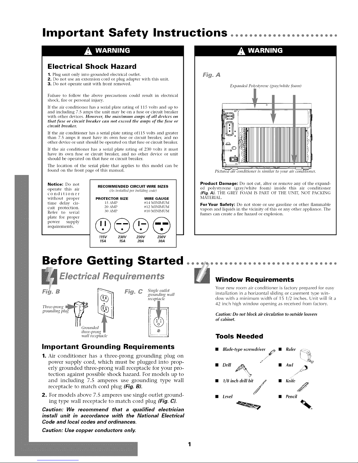
Hgo A
Expamled Polystyrene gray/white foam)
similar to yourairconditioueT:
Notice: Do not
operate this air
conditioner
without proper
time delay cir-
cuit protection,
Refer to serial
plate for proper
power supply
requirements,
RECOMMENDED CIRCUIT WIRE SIZES
(As iustalled per buildi_l,,¢ co&)
PROTECTOR SIZE WIRE GAUGE
1S AMP #14 MINIMUM
20 AMP #12 MINIMUM
30 AMP # 10 MINIMUM
@©©@
115V 230V 230V 230V
15.4 15.4 20A 30A
Before Getting Started o°°
Electrical Requfyements
Si1_?le outlet
groundin,,q wall
Important Grounding Requirements
1. Air conditioner has a three-prong grounding plug on
power supply cord, which must be plugged into prop-
erly grounded three-prong wall receptacle for your pro-
tection against possible shock hazard, For models up to
and including 7,5 amperes use grounding type wall
receptacle to match cord plug (Fig. B).
2. For models above 7,5 amperes use single outlet ground-
ing type wall receptacle to match cord plug (Fig. C).
Caution: We recommend that a qualified electrician
install unit in accordance with the National Electrical
Code and local codes and ordinances.
Caution: Use copper conductors only.
Product Damage: Do not cut, alter or remove any of the expand-
ed polystyrene (gray/white foam) inside this air conditioner
(Fig. AI. THE GREY FOAM IS PART OF THE UNIT, NOT PACKING
MATERIAL.
For Your Safety: Do not store or use gasoline or other flaInmable
vapors and liquids in the vicinity of this or any other appliance. The
fumes can create a fire hazard or explosion.
°°°°°°°°°°°°°°°°°°°°°°°°°°O
Window Requirements
Your new room air conditioner is factory prepared for easy
installation in a horizontal sliding or casement type win-
dow with a minimum width of 15 1/2 inches. Unit will fit a
42 inch high window opening as received from factory.
Caution: Do not block air circulation to outside louvers
of cabinet.
Tools Needed
• Blade-typescrew&iverj_ • Ruler (__)
• Drill _ • Awl _C/_
• 1/Sinch &illbit /_
• Level
X/
°"
• Knife
,/
• Pencil
Page 3
Installation°°°°°°°°°°°°°°°°°°°°°°°°°°°°°°°°°°°°°°°°°°°°°°°°
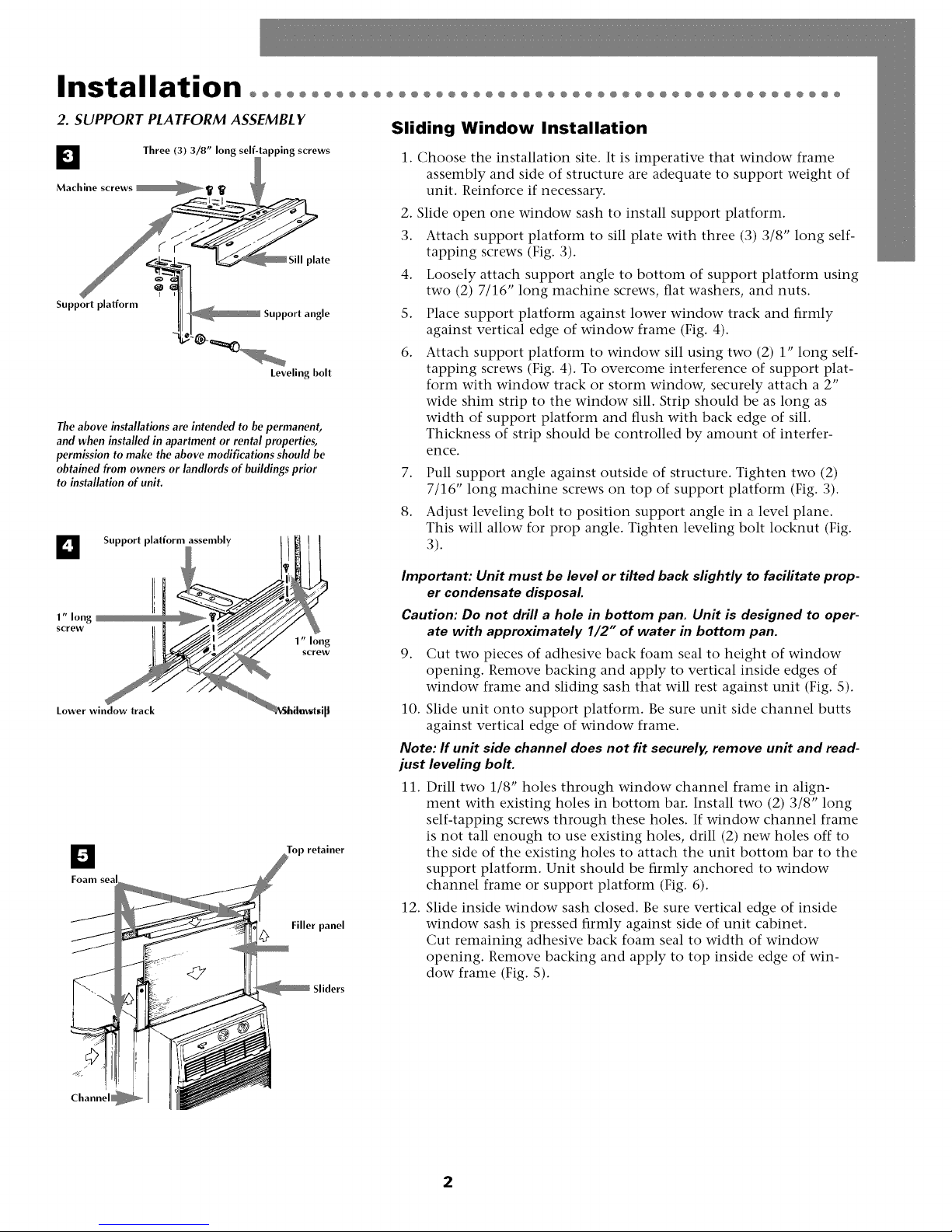
2. SUPPORT PLATFORM ASSEMBL Y
D Three (3) 3/8" long sel| apping screws
Machine screws __ _,
Support platform
The above installations are intended to be permanent,
and when installed in apartment or rental properties,
permission to make the above modifications should be
obtained from owners or landlords of buildings prior
to installation of unit.
_ plate
II _ Support angle
Leveling bolt
Support platform assembly !
..............
El
Foam seal
J
J
J
oP retainer
Filler panel
Sliding Window Installation
1. Choose the installation site. It is imperative that window frame
assembly and side of structure are adequate to support weight of
unit. Reinforce if necessary.
2. Slide open one window sash to install support platform.
3. Attach support platform to sill plate with three (3) 3/8" long self-
tapping screws (Fig. 3).
4. Loosely attach support angle to bottom of support platform using
two (2) 7/16" long machine screws, flat washers, and nuts.
S. Place support platform against lower window track and firmly
against vertical edge of window frame (Fig. 4).
6. Attach support platform to window sill using two (2) 1" long self-
tapping screws (Fig. 4). To overcome interference of support plat-
form with window track or storm window, securely attach a 2"
wide shim strip to the window sill. Strip should be as long as
width of support platform and flush with back edge of sill.
Thickness of strip should be controlled by amount of interfer-
ence.
7. Pull support angle against outside of structure. Tighten two (2)
7/16" long machine screws on top of support platform (Fig. 3).
8. Adjust leveling bolt to position support angle in a level plane.
This will allow for prop angle. Tighten leveling bolt locknut (Fig.
3).
Important: Unit must be level or tilted back slightly to facilitate prop-
er condensate disposal.
Caution: Do not drill a hole in bottom pan. Unit is designed to oper-
ate with approximately 1/2" of water in bottom pan.
9. Cut two pieces of adhesive back foam seal to height of window
opening. Remove backing and apply to vertical inside edges of
window frame and sliding sash that will rest against unit (Fig. S).
10. Slide unit onto support platform. Be sure unit side channel butts
against vertical edge of window frame.
Note: If unit side channel does not fit securely, remove unit and read-
just leveling bolt.
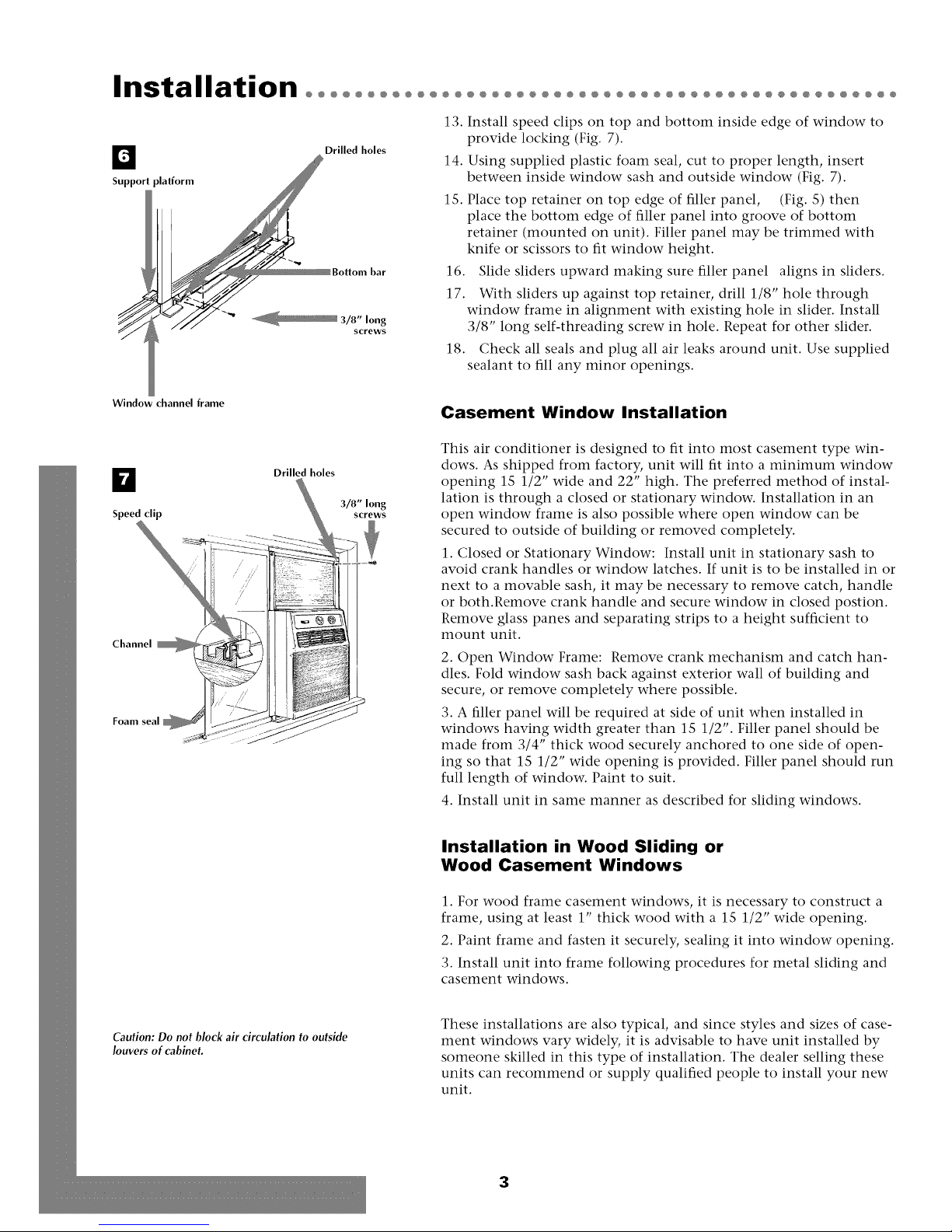
11. Drill two 1/8" holes through window channel frame in align-
ment with existing holes in bottom bar. Install two (2) 3/8" long
self-tapping screws through these holes. If window channel frame
is not tall enough to use existing holes, drill (2) new holes off to
the side of the existing holes to attach the unit bottom bar to the
support platform. Unit should be firmly anchored to window
channel frame or support platform (Fig. 6).
12. Slide inside window sash closed. Be sure vertical edge of inside
window sash is pressed firmly against side of unit cabinet.
Cut remaining adhesive back foam seal to width of window
opening. Remove backing and apply to top inside edge of win-
dow frame (Fig. S).
Sliders
2
Page 4
Installation°°°°°°°°°°°°°
13.
D Drilled holes 14.
Support
1S. Place top retainer on top edge of filler panel, (Fig. S) then
16. Slide sliders upward making sure filler panel aligns in sliders.
17. With sliders up against top retainer, drill 1/8" hole through
18. Check all seals and plug all air leaks around unit. Use supplied
@@@@@@@@@@@@@@@@@@@@@@@@@@@@@@@@@@@
Install speed clips on top and bottom inside edge of window to
provide locking (Fig. 7).
Using supplied plastic foam seal, cut to proper length, insert
between inside window sash and outside window (Fig. 7).
place the bottom edge of filler panel into groove of bottom
retainer (mounted on unit). Filler panel may be trimmed with
knife or scissors to fit window height.
window frame in alignment with existing hole in slider. Install
3/8" long self-threading screw in hole. Repeat for other slider.
sealant to fill any minor openings.
Window channel frame
D
Speed clip
Channel
Drilled holes
3/8" long
screws
Casement Window Installation
This air conditioner is designed to fit into most casement type win-
dows. As shipped from factory, unit will fit into a minimum window
opening 1S 1/2" wide and 22" high. The preferred method of instal-
lation is through a closed or stationary window. Installation in an
open window frame is also possible where open window can be
secured to outside of building or removed completely.
1. Closed or Stationary Window: Install unit in stationary sash to
avoid crank handles or window latches. If unit is to be installed in or
next to a movable sash, it may be necessary to remove catch, handle
or both.Remove crank handle and secure window in closed postion.
Remove glass panes and separating strips to a height sufficient to
mount unit.
2. Open Window Frame: Remove crank mechanism and catch han-
dles. Fold window sash back against exterior wall of building and
secure, or remove completely where possible.
3. A filler panel will be required at side of unit when installed in
windows having width greater than 1S 1/2". Filler panel should be
made from 3/4" thick wood securely anchored to one side of open-
ing so that 1S 1/2" wide opening is provided. Filler panel should run
full length of window. Paint to suit.
4. Install unit in same manner as described for sliding windows.
Installation in Wood Sliding or
Wood Casement Windows
Caution:Do not block air circulation to outside
louvers of cabinet.
1. For wood frame casement windows, it is necessary to construct a
frame, using at least 1" thick wood with a 1S 1/2" wide opening.
2. Paint frame and fasten it securely, sealing it into window opening.
3. Install unit into frame following procedures for metal sliding and
casement windows.
These installations are also typical, and since styles and sizes of case-
ment windows vary widely, it is advisable to have unit installed by
someone skilled in this type of installation. The dealer selling these
units can recommend or supply qualified people to install your new
unit.
3
Page 5
Operation°°°°°°°°°°°°°°°°°°°°°°°°°°°°°°°°°°°°°°°°°°°°°°°°°°
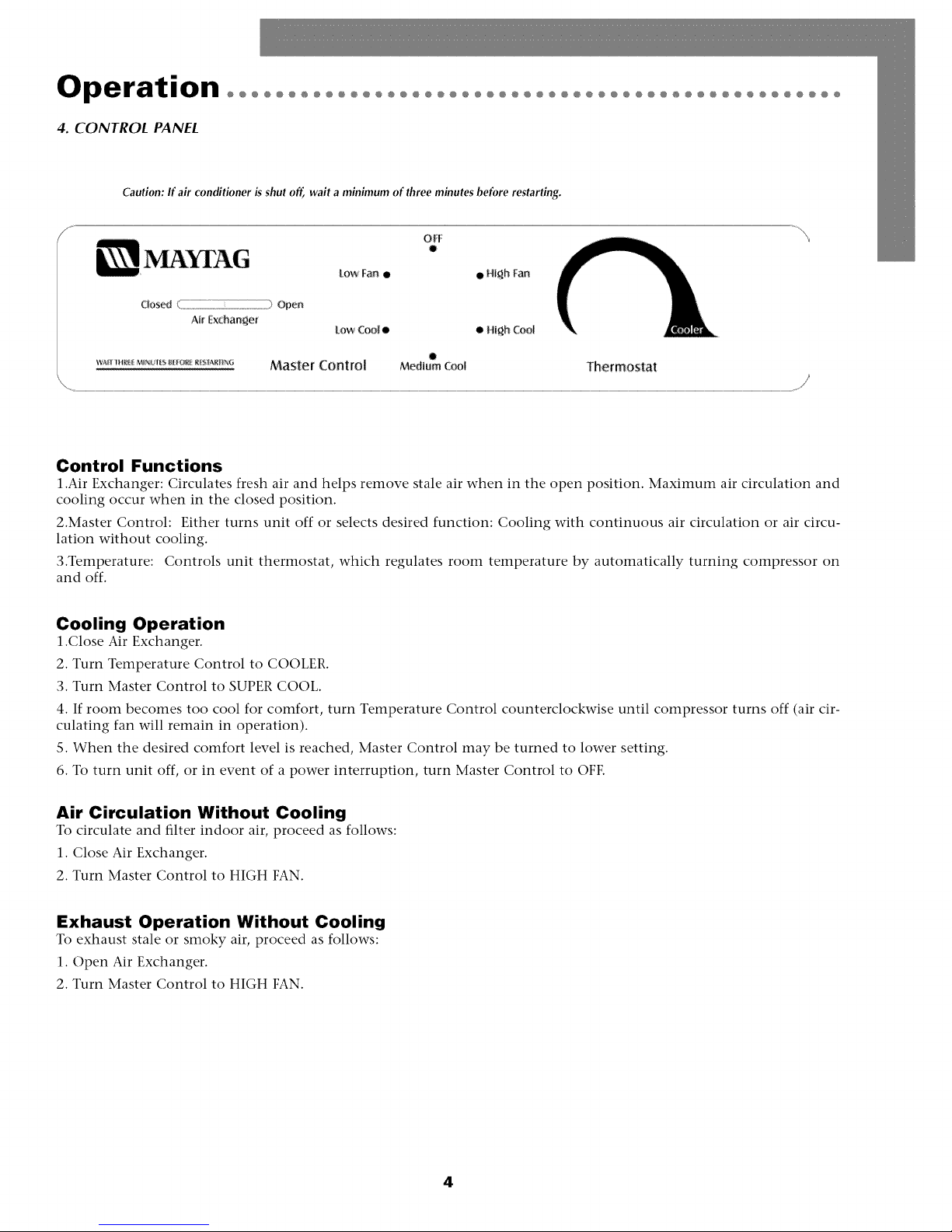
4. CONTROL PANEL
Caution: If air conditioner is shut off, wait a minimum of three minutes before restarting.
LowFan • • High Fan
Closed .............................................................................................................Open
AirExchanger
Master CoNtro[ Mediumcool Thermostat
Control Functions
1.Air Exchanger: Circulates fresh air and helps remove stale air when in tile open position. Maximum air circulation and
cooling occur when in the closed position.
2.Master Control: Either turns unit off or selects desired function: Cooling with continuous air circulation or air circu-
lation without cooling.
3.Temperature: Controls unit thermostat, which regulates room temperature by automatically turning compressor on
and off.
LowCool• • High Co_l
o
Cooling Operation
1.Close Air Exchanger.
2. Turn Temperature Control to COOLER.
3. Turn Master Control to SUPER COOL.
4. If room becomes too cool for comfort, turn Temperature Control counterclockwise until compressor turns off (air cir-
culating fan will remain in operation).
S. When the desired comfort level is reached, Master Control may be turned to lower setting.
6. To turn unit off, or in event of a power interruption, turn Master Control to OFF.
Air Circulation Without Cooling
To circulate and filter indoor air, proceed as follows:
1. Close Air Exchanger.
2. Turn Master Control to HIGH FAN.
Exhaust Operation Without Cooling
To exhaust stale or smoky air, proceed as follows:
1. Open Air Exchanger.
2. Turn Master Control to HIGH FAN.
4
Page 6
Maintenance°°°°°°°°°°°°°°°°°°°°°°°°°°°°°°°°°°°°°°°°°°°°°°
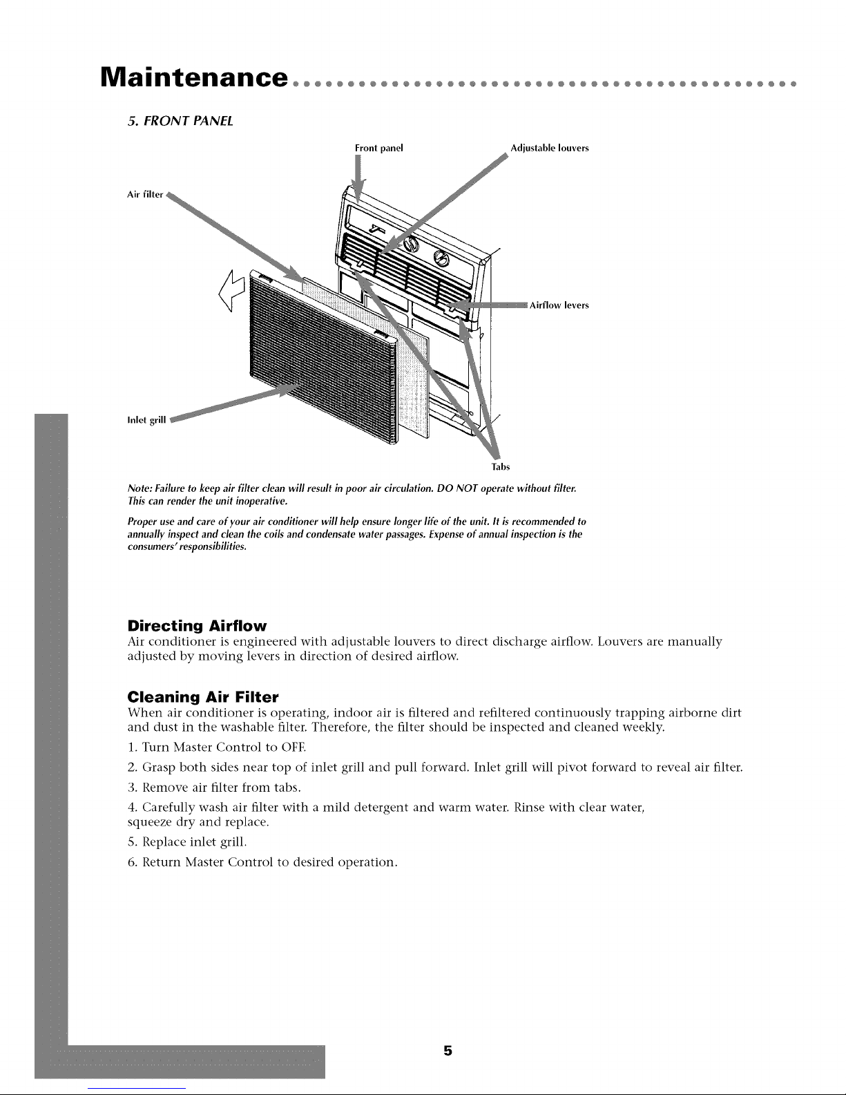
5. FRONT PANEL
Front panel Adjustable louvers
Air filter _
Inlet gl
Tabs
Note: Failure to keep air filter clean will result in poor air circulation. DO NOT operate without filter
This can render the unit inoperative.
Proper use and care of your air conditioner will help ensure longer life of the unit. It is recommended to
annually inspect and clean the coils and condensate water passages. Expense of annual inspection is the
consumers' responsibilities.
Directing Airflow
Air conditioner is engineered with adjustable louvers to direct discharge airflow. Louvers are manually
adjusted by moving levers in direction of desired airflow.
Cleaning Air Filter
When air conditioner is operating, indoor air is filtered and refiltered continuously trapping airborne dirt
and dust in the washable filter. Therefore, the filter should be inspected and cleaned weekly.
1. Turn Master Control to OFE
2. Grasp both sides near top of inlet grill and pull forward. Inlet grill will pivot forward to reveal air filter.
3. Remove air filter from tabs.
4. Carefully wash air filter with a mild detergent and warm water. Rinse with clear water,
squeeze dry and replace.
S. Replace inlet grill.
6. Return Master Control to desired operation.
5
Page 7

Warrantyooooooooooooooooooooooooooooooooooooooooooooooooooo
For Models Installed
in North America - If Service
or Parts are Required
First, make the recommended checks. If it appears that ser-
vice or parts are still required, see your room air condition-
er warranty "How to Obtain Warranty Service or Parts".
For Models Installed
Outside North America
For room air conditioners purchased for use outside North
America, the manufacturer does not extend any warranty
either expressed or implied. Consult your local dealer for
any warranty terms extended by the importer in your
country.
Room Air Conditioner Warranty
(Within the 48 contiguous United States, state of Hawaii,
the District of Columbia, Puerto Rico and Canada)
Full (FiveYear) Parts and Labor Warranty
During the five years after the date of original purchase,
Fedders Appliances will, through its authorized servicers
and free of charge to the owner or any subsequent user,
repair or replace any parts which are defective in material
or workmanship due to normal use. Ready access to the air
conditioner is the responsibility of the owner.
Note: In the event of any required parts replacement with-
in the period of this warranty, Fedders Appliances replace-
ment parts shall be used and will be warranted only for the
period remaining on the original warranty.
Exceptions
The above warranty does not cover failure to function
caused by damage to the unit while in your possession
(other than damage caused by defect or malfunction), or
by its improper installation, or by unreasonable use of the
unit, including without limitation, failure to provide rea-
sonable and necessary maintenance or to follow the writ-
ten Installation and Operating Instructions. If the unit is
put to commercial, business, rental, or other use or appli-
cation other than for consumer use, we make no war-
ranties, express or implied, including but not limited to,
any implied warranty of merchantability or fitness for par-
ticular use or purpose.
THE REMEDIES PROVIDED FOR IN THE ABOVE EXPRESS
WARRANTY ARE THE SOLE AND EXCLUSIVE REMEDIES
THEREFOR, NO OTHER EXPRESS WARRANTIES ARE
MADE. ALL IMPLIED WARRANTIES, INCLUDING BUT NOT
LIMITED TO ANY IMPLIED WARRANTY OF MER-
CHANTABILITY OR FITNESS FOR A PARTICULAR USE OR
PURPOSE, ARE LIMITED IN DURATION TO FIVE YEARS
FROM THE DATE OF ORIGINAL PURCHASE. IN NO EVENT
SHALL Fecldet:_Appliances BE LIABLE FOR INDIRECT, INCI-
DENTAL, OR CONSEQUENTIAL DAMAGES, EVEN IF
ADVISED IN ADVANCE OF THE POSSIBILITY OF SUCH
DAMAGES. NO WARRANTIES, EXPRESS OR IMPLIED, ARE
MADE TO ANY BUYER UPON RESALE.
Some states do not allow limitations on how long an
implied warranty lasts or do not allow the exclusion or
limitation of incidental or consequential damages, so the
above limitations or exclusions may not apply to you.
This warranty gives you specific legal rights, and you may
also have other rights which may vary from state to state.
No warranties are made for units sold outside of the above
stated areas. Your distributor or final seller may provide a
warranty on units sold outside of these areas.
How to Obtain
Warranty Service or Parts
Service for your room air conditioner will be provided by
CareCo, a division of the manufacturer with authorized
independent CareCo servicers nationwide.
Note: Before calling for service, carefully read the
Installation and Operating Instructions booklet. Then ff
you need service:
1. Call a CareCo authorized servicer and advise them of
model number, serial number, date of purchase and
nature of complaint. Service will be provided during
normal working hours. Contact your dealer for the
name of an authorized servicer if unknown to you.
2. If your dealer is unable to give you the name of a ser-
vicer or if you need other assistance, call the following
toll-free number for the name of an authorized servicer
or authorized parts distributor:
1-866-MAYTAG 1
or you may write:
CareCo, Service Department
415 W. Wabash Ave., RO. Box 200
Effingham, IL 62401
Proof of Purchase Date
It is the responsibility of the consumer to establish the
original purchase date for warranty purposes. We recom-
mend that a bill of sale, cancelled check, or some other
appropriate payment record be kept for that purpose.
6
Page 8

Instrucciones importantes de seguridadoooooooooo
Peligro de descarga el6ctrica
1. Enchufe la unidad en till tonlacorriente con conexi6n a tierra,
2. No use un cable de extensi6n ni un adaptador de enchufe con este
aparato.
3. No 1o haga funcionar sin la cubierta delantera.
El no seguir las precauciones enumeradas anteriormente podria
causar descargas elOctricas, incendio o lesiones personales,
Si el acondicionador de aim trae en la placa tma clasificaci6n de 115
voltios y hasta 7,S amperios inclusive, la unidad puede ir conectada
al mismo fusible o cortacircuitos junto con otros aparatos, Sin
embargo, el mdximo amperaje de todos los aparatos conectados a
la vez a ese fusible o cortacilx'uitos no debe ser mayor que la capaci-
dad (amperios) de dicho fusible o cortacircuitos.
Si el acondidonador de aim trae en la placa una clasificad6n de 115
voltios v m,_s de 7.5 amperios, entonces debe ir conectado a su pro-
pio fusible o cortadrcuitos y ningfn otro aparato o unidad se podrfi
conectar a dicho fusible o cortadrcuitos.
Si el acondicionador de aire trae en la placa una clasificaci6n de 230
voltios, entonces debera ir conectado a su propio fusible o cortacir-
cuitos y ningfin otro aparato o unidad se podra conectar a dicho
fusible o cortacircuitos.
La ubicaci6n de la placa con la serie correspondiente a este modelo
se encuentra en la pfigina del frente de este manual.
Aviso: No haga tim.
cionar estre aire acondi-
cionado sin un circuito
temporizador que
brinde la protecci6n
adecuada. En la placa
de identificaci6n apare-
cen los requisitos cor-
rectos de alimentaci6n.
TAIVIAI_IOSRECOMENDADOS PARA LOS
ALAMBRES DEL CIRCUITO
(Instalado s(',qfiHlos n'ghmlentos d_"constrl_ccidn)
TAMAI_O DEL CALIBRE DEL
PROTECTOR ALAMBRE
15 AMP #14 MINLMO
20 AMP #12 MINIMO
O) AMP #10 MINIMO
Figo A
Poliestirem_ ex/)anditlo (Es])llllltl _{l'is//)lanca)
o
_' V¸
El aire acoudicionado de la foto es similar al suyo.
Dafio al producto: No corte, altere o retire ningdn pedazo de poli-
estireno expandido (espuma gris/blanca) que se encuentre dentro del
acondicionador de aim (Fig. A). EL POLIESTIRENO EXPANDIDO
FORMA PARTEDE LAUNIDAD, NO ES MATERIAL DE EMBALAJE,
Para su seguridad: No ahnacene ni utilice gasolina u otros vapores
y liquidos inflamables cerca de este artefacto o de cualquier otro arte-
facto, Los vapores pueden provocar un incendio o una explosi6n,
@©©@
116V 230V 230V 230V
15.4 15.4 20.4 30.4
Antes de empezarooooooooooooo
Req dstoa Data/a eleetdcoa
Recept&rulo mural
con salMa simple
de tmesta a tierra
Requistos importantes
para la conexi6n a tierra
1. E1 equipo de aire acondicionado tiene en el cord6n de
corriente un enchufe a tierra de tres puntas, el cual debe
set introducido en un tomacorriente de tres puntas
debidamente conectado a tierra para protecci6n contra
posibles descargas el_ctricos. Para modelos de hasta 7.S
amperios utilice un tipo de tomacorriente con conexi6n
a tierra, adecuado para el enchufe del equipo (Fig. BL
2. Para modelos de mils de 7.S amperios, utilice un tomacor-
riente con conexi6n a tierra para un solo enchufe (Fig.eL
Precaucion: Recomendamos que un electricista calificado
instale la unidad de acuerdo alas normas electicas
nacionales y las normas y regulaciones locales.
Precaucion: Utifice solamente conductores de cobre.
°°°°°°°°°°°°°°°°°°°°°°°°°O
de fdbrica para permitir una f;ici] instalaci6n en una
ventana con pane]es corredizos horizonta]es o de tipo
caja con un ancho mfnimo de 15 1/2 pulgadas, La
pulgadas de altura,
Precauci6n: No bloquee la circulaci6n del aire de lasrejil-
las exteriores del gabinete.
• Destornilladorcomfn _ Regla
• Taladro /_ • tezna
• Punta de tala&o de x?ll Cuchillo
• Nivel _._o__ • t_plz
Requisitos de la ventana
El nuevo acondicionador de aire viene preparado
unidad cabr4 en una ventana con una abertura de 42
Herramientas necesarias
/
J
1/8 de pulgada
/
/
Page 9

Instalaci6n oooooooooooooooooooooooooooooooooooooooooooooooo
D Tres (3) tornillos 3/8" de
Tornillos para metal __
D Plataforma de
Tornillo
de 1"
de largo
Via inferior de la ventana la ventana
D Retenedor superior
Sellsdor de espuma
apoyo de montaje
largo autorroscantes
nivelaci6n
Tornillo
de largo
_uicio de
Franja de madera
de relleno
de 1"
Instalaci6n en ventana corrediza
l.Escoja el lugar de la instalaci6n. Es imperativo que el conjunto del
marco de la ventana y el lado de la estructura sean adecuados
para soportar el peso de la unidad; de lo contrario, los deberfi reforzar.
2. Abra un bastidor de la ventana para instalar la plataforma de soporte.
3. Conecte la plataforma de soporte al alf4izar mediante los tres (3)
tornillos autorroscantes de 3/8" de largo (Fig. 3).
4. Conecte flojamente el fingulo de apoyo a la base de la plataforma de
apoyo mediante dos (2) tornillos para metal de 7/16 pulgada de
largo, arandelas planas y tuercas.
S. Coloque la plataforma de apoyo contra la via inferior de la ventana y
firmemente contra el borde vertical del marco de la ventana(Fig.4).
6. Fijar la plataforma de soporte al alfhizar o tablilla de la ventana usando
dos (2) tornillos de 1" de largo (Fig. 4). Para superar la interfer-
encia de la plataforma de soporte con el canal de la ventana o la con-
traventana, sujete fijamente una curia de madera de 2" de ancho al
alfhizar o tablilla de la ventana. La franja de madera debera ser tan
larga como es el ancho de la ventana y a nivel del alfhizar o tablilla de
la ventana. Determine el espesor de la franja de madera de
acuerdo al espacio entre el canal de la ventana y la plataforma de
soporte.
7. Empuje el _ngulo de apoyo hacia la parte exterior de la estructura.
Apriete dos (2) tornillos para metal de 7/16" de largo en laparte
superior de la plataforma de apoyo (Fig. 3).
8. Ajuste un perno nivelador para ubicar el _ngulo de apoyo en un piano
nivelado. Esto permitir_ establecer un _ngulo adecuado. Apriete la
tuerca de sujeci6n del perno nivelador (Fig. 3).
Importante: La unidad debe estar nivelada o inclinada levemente hacia
atras para facilitar la eliminacion de la condensacion.
Precauci6n: No perfore un agujero en la bandeja inferior. La unidad se
ha dise_ado para que funcione con aproximadamente 1/2 pulgada de
agua en la bandeja.
9.Corte dos trozos de sellador de espuma con un lado adhesiw_ de la
misma altura de la abertura de la ventana. Retire el revestimiento y
aplique a los bordes interiores verticales del marco de la ventana y al
bastidor deslizante que se apoye contra la unidad (Fig. S).
10.Deslicelo sobre la plataforma de apoyo.
Cerci6rese de que del canal lateral de la unidad hace tope con el borde
vertical del marco de la ventana.
Las instalaciones descritas son de tipo permanente; cuando se
efectdan en un departamento o en propiedades alquiladas, se debe
solicitar un permiso especial a los propietarios o duefios para Ile-
var a cabo dichas modificaciones antes de instalar la unidad.
Nota: Si el canal lateral de la unidad no encaja firmemente, retire la
unidad y vuelva a ajustar el perno nivelador.
8
Page 10

Instalaci6n oooooooooooooooooooooooooooooooooooooooooooooooo
D Orificios laterales
Plataforma de apoyo
11.Taladre dos agujeros de 1/8" a tray,s del marco del canal
de la ventana alinefindolos con los agujeros al fondo del
canal. Instale dos (2) tornillos de 3/8" de largo por estos
agujeros. Si el marco del canal de la ventana es lo suficiente-
mente alto para usar los agujeros existentes, taladre dos (2)
agujeros nuew)s a los lados de esos agujeros para sujetar el
fondo de la unidad con la plataforma de soporte. La unidad
debe estar firme mente sujeta al canal del marco de la ven-
tana o a la plataforma de soporte (Fig. 6).
12. Deslice el bastidor interior de la ventana cerrada.
CerciSrese de que el borde vertical del bastidor interior de la
ventana est_ firmemente apoyado contra el costado del
gabinete de la unidad. Corte el resto del sellador de espuma
con respaldo adhesivo del mismo ancho de la abertura de la
ventana. Retire el revestimiento y aplique al borde interior
superior del marco de la ventana (Fig. S).
13.Instale sujetadores tipo "speed clips" en el borde interior
superior e inferior de la ventana para poder cerrarla (Fig. 7).
14. Utilizando el sello de espuma plfistica suministrado,
corte un pedazo adecuado e introdfizcalo entre el bastidor
interno de la ventana y la ventana externa (Fig. 7).
15. Coloque el retenedor superior en el borde superior del
panel de relleno, (Fig. S) luego coloque el borde inferior del
panel de relleno en la ranura del retenedor inferior
(montado en la unidad). E1panel de relleno puede recor-
tarse con un cuchillo o tijeras para que encaje en la altura
de la ventana.
16. Haga deslizar las deslizadoras hacia arriba cerciorfindose
de que est_n alineadas con el panel de relleno.
17.Con las correderas apegadas al ret_n superior, perfore un
orificio de 1/8" a trav_s del marco de la ventana de modo
que quede alineado con el orificio existente en la corred-
era. Instale el tornillo autorroscante de 3/8" en el orificio.
Repita el procedimiento en la otra corredera.
18. Verifique todos los selladores y obstruya todas las filtra-
clones de aire alrededor de la unidad. Usar el sellador
proveido para llenar pequefias aberturas.
Marco acanalado de la ventana
D
Sujetadores tipo "Speed clip"
Canal
Sellador de
Barra inferior
Orificios laterales
Tornillo
de 3/8"
de largo
Tornillo
de 3/8"
de largo
9
Page 11

FuncionamientOoooooooooooooooooooooooooooooooooooooooooo
4. TABLERO DE CONTROL Precauci6n: Si apaga el acondicionador de aire, espere por Io menos tres minutos antes de volver a encenderlo.
LowFan t i Ht_h Fan
Closed .............................................................................................................Open
AirE×chan_er
Master CoNtfo[ Medium Cool Thermostat
Funciones de los controles
1.1ntercambiador de aire "Air Exchanger":
Cuando se abre el acondicionador, circula air fresco y se elimina el air viciado. AI cerrarse, circula el
ma'ximo de aire y se produce enfriamiento.
2. Control maestro "Master Control":
Sirve para encender y apagar la unidad. Permite seleccionar la funci6n deseada de la unidad: enfri-
amiento con circulaci6n de aire o circulaci6n de aire sin enfriamiento.
LowCool• • High Cool
i
3, Temperatura "Temperature":
Controla el termostato de la unidad, que regula la temperatura de la habitaci6n al prender y apagar
automa'ticamente el compresor.
Funcionamiento del enfriamiento
1. Ponga el intercambiador de aire en la posici6n de cerrado.
2. Ponga el control de temperatura en la posici6n ma's frfa "COOLER".
3. Ponga el control maestro en fifo ma'ximo "SUPER COOL".
4.. Si la habitaci6n se enfrfa demasiado, haga girar la perilla del termostato de derecha a izquierda
hasta que se apague el compresor (el ventilador de circulaci6n de aire seguira" en funcionamiento).
5. Cuando se alcanza el nivel de confort deseado podra" ponerse el control maestro en un valor ma's
bajo "NORMAL COOL" o "LOW COOL".
6. Para apagar la unidad, o en el caso de una interrupci6n de corriente, ponga el control maestro en
posici6n apagado "OFF".
Circulaci6n de aire sin enfriamiento
Para que el aire circule y se filtre, hay que proceder de la siguiente manera:
1. Ponga el intercambiador de aire en la posici6n de cerrado.
2. Ponga el control maestro en ventilador alto "HIGH FAN".
Funcionamiento de ventilaci6n sin enfriamiento
Para expulsar el aire viciado, es necesario hacer Io siguiente:
1. Ponga el intercambiador de aire en la posici6n de abierto.
"& Ponga el control maestro en ventilador alto.
10
Page 12

Mantenimiento oooooooooooooooooooooooooooooooooooooooooo
5. PANEL FRONTAL
Panel frontal Rejillas
Filtro de aire
Advertencia: El no mantener limpio el filtro podda resultar en baja circulaci6n del aim. NUNCA haga funcionar la
unidad sin el filtro ya que puede quedar inutilizable.
El uso y mantenimiento adecuados del acondicionador de air prolongar_ la vida 6til de la unidad. Se recomienda
inspeccionar y limpiar anualmente el serpentfn y los pasajes para agua de condensaci6n. El cliente deber_ cubrir los
gastos de inspecci6n anual.
directrices ajustables
Palancas de
corriente de aire
Presillas
Orientaci6n de la
corriente de aire
La unidad viene equipada con rejillas directrices ajustables que permiten dirigir la descarga de la corriente de aire. Las rejillas
pueden ajustarse manua]mente moviendo ]as pa]ancas en ]a direcci6n deseada.
Limpieza del filtro de aire
Cuando el acondicionador de aire est4 en funcionamiento, el aire interior se filtra y refi]tra continuamente, atrapando ]a suciedad
y e] po]vo suspendidos en e] aire en e] fi]tro ]avab]e. Por ]o tanto, e] fi]tro deber_i inspeccionarse y ]impiarse una vez por semana.
1, Ponga e] contro] maestro en posici6n apagado.
2, Tome ambos ]ados cerca de ]a parte superior de ]a reji]]a de entrada y ja]e hacia adelante. La reji]]a girard1 hacia ade]ante y
dejar_i e] fi]tro de aire a] descubierto.
3, Desmonte e] fi]tro de aire de ]as presi]]as.
4, Lave cuidadosamente e] fi]tro de aire con un detergente suave y agua tibia. Enju_igue]o con agua ]impia, deje escurrir bien y
vuelva a co]ocarlo.
5, Vue]va a co]ocar e] parri]]a de entrada.
6, Ponga e] contro] maestro en ]a operaci6n deseada.
11
Page 13

Garantiaoooooooooooooooooooooooooooooooooooooooooooooooooooo
Para modelos instalados en
Norteam6rica - En caso de necesidad
de servicio o piezas
Haga primer() las verificaciones recomendadas. En caso
de necesitarse servicio o piezas, consulte en la garantia de
su acondicionador de aire en la secci6n "C6mo obtener
servicio o piezas de garantia'.
Para modelos instalados
fuera de Norteam_rica
Para aires acondicionados comprados para uso fuera de
Norteam_rica el fabricante no otorgarfi ninguna garantia
implicita o explicita. Consulte a su distribuidor autoriza-
do sobre las condiciones de la garantia extendida pot el
importador de los equipos de su pais.
Garantia del acondicionador de aire
(Dentro de los 48 estados contiguos de los Estados
Unidos, estado de Hawai, Distrito de Columbia, Puerto
Rico y Canada)
Garantia para todas las piezas (cinco a_os)
y mano de obra
A partir de la fecha de compra y durante un periodo de
cinco aflos, Fedders Appliances, mediante sus estaciones
de servicio autorizadas, repararfi o reemplazarfi sin costo
alguno para el propietario o usuario, cualquier pieza que
presente daflos de material o mano de obra derivados del
uso normal del producto. Es responsabilidad del propi-
etario facilitar el acceso al acondicionador de aire para
realizar los servicios de reparaci6n.
Nota: En caso de que se requiera reemplazar una pieza
mientras la garantia esta vigente, se utilizaran los
repuestos de Fedders Appliances los cuales continuaran
en vignecia solamente durante el resto del periodo de
garantia de la unidad.
Excepciones
La garantia antes indicada no cubre las fallas de fun-
cionamiento causadas por daflos que sufra la unidad
mientras _sta est_ en posesi6n del usuario (excluyendo los
daflos causados por defecto o funcionamiento defectu-
oso), o por la instalaci6n incorrecta, o la utilizaci6n inde-
bida de la unidad, incluyendo pero sin limitarse a ello, la
negligencia en proporcionar el mantenimiento necesario
y adecuado o en seguir las "instrucciones de Instalaci6n y
Uso" indicadas por escrito. En caso de utilizarse la unidad
para fines comerciales, de negocios, de arriendo u otto uso
o aplicaci0n que no sea el uso del consumidor, no otorg-
amos garantia explicita ni implicita, incluyendo, pero sin
limitarse a, toda garantia implicita de negociabilidad o
idoneidad para un uso o finalidad particular.
LAS SOLUCIONES EXPUESTAS EN LA GARANTIA ANTERI-
OR SON EXCLUSIVAS. SE RECHAZA CUALQUIER OTRA
GARANTIA YA SEA EXPRESA 0 IMPLICITA, INCLUYENDO,
PERO SIN LIMITARSE A ELL(), TODAS LAS GARANTIAS DE
COMERCIABILIDAD 0 IDONEIDAD PARA UN FIN EN PAR-
TICULAR DURANTE CINCO ANOS A PARTIR DE LA FECHA
DE COMPRA. BAJO NINGUNA CIRCUNSTANCIA Fedders
Appliances SE HARA RESPONSABLE POR NINGUN DANO
DIRECT(), INDIRECT() 0 CONSECUENCIAL, SIN IMP(JR-
TAR LA CAUSA DE LA ACCION, AUN CUANDO Feddet_s
Appliances HAYA SIDO ADVERTIDO CON ANTERIORIDAD
DE LA POSIBILIDAD DE DICHOS DANOS. NO SE OFRECE
NINGUNA GARANTIA EXPRESA 0 IMPLICITA A COM-
PRADORES DESPUES DE LA RE VENTA.
Algunos estados no permiten limitar el tiempo de
duraci6n de una garantia implicita ni permiten excluir ni
limitar los daflos incidentales o emergentes, de modo que
las limitaciones o exclusiones antes indicadas podrian no
aplicarse en su caso. Esta garantia le otorga derechos
legales especificos. Usted podria tener tambi_n otros dere-
chos que pueden variar de estado a estado.
No se ofrecen garantias para las unidades vendidas fuera
de las fireas antes indicadas. Su distribuidor o vendedor
final podria proporcionar una garantia para las unidades
vendidas fuera de estas fireas.
C6rno obtener servicio
o piezas de garantia
E1 servicio para su acondicionador de aire serfi provisto por
CareCo, una divisi6n del fabricante con estaciones de ser-
vicio independientes CareCo autorizadas en todo el pais.
Nota: Antes de solicitar servicio, lea cuidadosamente el
folleto de "lnstrucciones de Instalacion y Uso'." Luego, si
necesita servicio:
1. Llame a un taller de servicio autorizado CareCo y sum-
inistreles el nfimero de modelo, nfimero de serie, la fecha
de compra y la naturaleza del problema. E1 servicio se
prestarfi durante horas normales de trabajo.
Comuniquese con su distribuidor para obtener recomen-
daciones sobre una estaci6nde servicio autorizada.
2. Si su distribuidor no puede proporcionarle el nombre
de un taller de servicio o si necesita otro tipo de asis-
tencia, llame al siguiente nfimero gratis para obtener el
nombre de un taller de servicio autorizado o dis-
tribuidor de piezas autorizado:
1-866-MAYTAG 1
o escriba al:
Departamente de Servicio de CareCo
415 W. Wabash Ave., RO. Box 200
Effingham, IL 62401 EE. UU.
Prueba de la fecha de compra
E1 establecimiento de la fecha de compra original para
efectos de la garant{a es responsabilidad del consumidor.
Recomendamos mantener la factura de compra, el cheque
cancelado o algfin otto registro de pago apropiado para
dicho efecto.
12
Page 14

Directives de s6curit6 importanteSooooooooooooooooo
Danger de choc 41ectrique
1. N'enficher le cliinatiseur que clans une prise _lectrique raise fl la
term,
2. Ne pas se servir d'une rallonge ou d'un adaptateur avec cet
appareil.
3. Ne pas faire marcher le climatiseur si le panneau avant a OtO retir&
Suivre les prOcautions indiquOes ci-dessus pour Oviter tout risque
d'Olectrocution, d'incendie ou de lOsion corporelle.
Si la plaque de sOrie du clilnatiseur indique une tension nominale de
11 S volts et une intensitO en amperes nominale allant iusqu' fi 7,SA,
l'appareil peut _tre branchO sur le m&ne fusible ou disjoncteur que
d'autres appareils. Toutef!_is, l'intensit( maximale en ampfres de
l'ensemble des appareils branchds sur ce fusible ou disjoucteur ne
dolt pas d(passer celle du filsible ou du disjoncteur.
Si la plaque de sOrie du clilnatiseur indique une tension en volts
nominale de 11,5 volts et une intensitO en amperes nominale
supOrieure fl 7,S A, l'appareil doit _tre dotO de son propre fusible ou
disjoncteur et aucun autre appareil ne dolt y &re branch&
Si la plaque de sOrie du clilnatiseur indique une tension en volts
nominale de 230 volts, l'appareil doit &re dotO de son propre fusible
ou disioncteur et aucun autre appareil ne dolt y _tre branchO.
L'emplacement de la plaque signaDtique applicable flce inod_le est
indiquO sur la page couverture du pr&ent manuel.
Avis: Ne pas utiliser
le climatiseur sans la
protection d'un circuit
de temporisation. Se
reporter fi la plaque sig-
nabtique pour toute
indication de puissance
exig_e.
CALIBRES DE FIL RECOMMANDI_S
(3ehm lOlstallatO_ stJ/ml&
/)ar ]d dodd 0" dO!_5[FHcOI!_)
PROTECTION CALIBRE
DU CIRCUIT DE FIL
1S ,4 N°14 MINIMUM
20 A N°12 MINIMUM
30 A N°I0 MINIMUM
Endommagement du produit: Ne pas couper, altOrer ou retirer le
polystyrene expansO (mousse grise/blanche) se trouvant 5 l'intOrieur
du climatiseur (Fig.A). LE STYROFOAM N'EST PAS UN EMBALLAGE,
IL FAIT PARTIE INTEGRALE DE L'APPAREIL.
Pour votre s4curit& Ne pas stocker ou utiliser de l'essence ou toute
autre vapeur ou liquide inflammable 5 proxilnitO de cet appareil ou
de tout autre. Les Omanations peuvent crOer un risque d'incendie ou
d'explosion.
Polystyr?ne expans(, (Mousse grise/bhmche)
o
L_q)pareil illuslT(, est semblable h votre cliumtiseur
@©©@
I15V 230V 230V 230V
16A 16A 20A 30A
Pr6paratifSooooooooooooooooooo
EMgences elec dque
• Tournevis h lame • R('gle
B
Fk:he h trois
DI'OC[I('S _1'('C
terre
Prise mill'ale h trois
l)l'oches l?l/ec teH'e
N_o C Prise murah,
UHiqlle avec tel'l'e
Importantes exigences de mise _ la terre
1. E1climatiseur est pourvu d'une fiche de mise _ la terre
trois broches sur le cordon _lectrique. Cette fiche dolt
&re branchhe sur une prise murale _ trois broches
dfiment mise _ la terre afin de prot_ger contre
d'_ventuels risques de chocs. Pour les modules allant
jusqu'au 7.S A inclusivement, utiliser une prise murale
de type mise _ la terre correspondant _ la fiche (Fig. B).
2. Pour les modhles de plus de 7.S A, utiliser une prise
murale simple de mise _ la terre correspondant _ la
fiche (Fig. C).
Attention: Nous recommandons que I'appareil soit monte
par un electricien competent conformement au Code elec-
trique national ainsi qu'au code et reglements Iocaux.
Attention: Utiliser uniquement des conducteurs en cuivre.
• Niveau __ • Crayon %
1. Le climatiseur est pr_par_ fi l'usine en vue d'un mon-
2. Faire la pose du climatiseur dans une fen&re 06 il y a
Mise en garde: Ne pas empOcher I'air de circuler vers
I'exterieur des Iouvres du coffret.
3. Toutes les pi_ces de soutien doivent &re fix&s solide-
°°°°°°°°°°°°°°°°°°°°°°°°°°°
ndcessa es
Spddffcado s de fa fe 8 re
tage dans des fen&res _ guillotine standard (le clima-
tiseur ne peut pas &re mont_ dans d'autres types de
fen&re sans modification, pri_re de consulter un tech-
nicien de montage comp&ent).
un d_gagement suffisant pour assurer un apport d'air
abondant _ l'appareil.
ment _ des surfaces fermes en bois, magonnerie ou
m&al.
13
Page 15

Montage°°°°°°°°°°°°°°°°°°°°°°°°°°°°°°°°°°°°°°°°°°°°°°°°°°°°°°°
D Trois (3) vis autotaraudeuses
_] Plaq base
Plate-forme de soulier IIII
3/8 po de long
.... II _ Eguerredesout,e.
de calage
D Plate-forme de soutien
I'assemblage
llp o_ies
Rail de fen_tre inf6rieur
D Didpoditif de
Joint de mousse sup6rieur
la fen_tre
Entretoise
retenue
J
J
J
Panneau de
remplissage
Glissi6res
2. PLATE-FORME DE SOUTIEN DE L'ASSEMBLAGE
Les installations ci-dessus sont permanentes. Pour une installation dans
un appartement ou un Iogement _ location, les modifications d6crites ci-
dessus doivent _tre approuv6es par le propri6taire de ces Iogements
avant de proc6der aux installations.
Montage dans une fen_tre coulissante
1.Choisir le lieu du montage. I1 est essentielque
l'ensemble de cadre de fen_tre et le c6t4 de
la structure puissent supporter ad_quatement
le poids de l'appareil. Renforcer au besoin.
2.Ouvrir l'un des cadres de vitre et installer la plaque de fixa-
tion.
3. Fixer la plaque de fixation sur l'appui de fen_tre _ l'aide de
trois (3) vis autotaraudeuses de 3/8" de long (Fig. 3).
4. Fixer, sans setter, l'_querre de soutien au bas de la plate-
forme de soutien _ l'aide de deux (2) vis _ m4taux de 7/16 de
po de long, de rondelles plates et d'_crous.
5. Placer la plate-forme de soutien contre le rail
de fen_tre inf_rieur et fermement contre le
bord vertical du cadre de fen_tre (Fig. 4).
6. Attacher la plate-forme de support _ l'appui de la fen_tre
l'aide de deux (2) vis autotaraudeuses de 1 po de longueur
(Fig. 4). Pour emp_cher que cette plate-forme n'empi_te sur la
glissi_re de la fen_tre coulissante ou la contre-fen_tre, attach-
er solidement une entretoise de 2 po de largeur _ l'appui de
fen_tre. La longueur de cette entretoise devrait _tre _gale _ la
largeur de la plate-forme de support, et son chant devrait _tre
align_ sur la rive artiste de l'appui. U_paisseur de l'entretoise
devrait _tre fonction de l'empi_tement de la plate-forme.
7. Tirer l'_querre de soutien contre l'ext4rieur de la structure.
Setter deux (2) vis _ m4taux de 7/16 de po de long sur le
dessus de la plate-forme de soutien (Fig. 3).
8. R_gler le boulon de nivellement afin de positionner l'_-
querre de soutien _ niveau. Ceci permettra d'obtenir l'angle
appropri_. Setter le contre-_crou du boulon de nivellement
(Fig. 3).
Remarque Importante: Le dispositif doit _tre de niveau ou
l_g_rement inclin4 vers l'arri_re pour faciliter l'_vacuation des
condensats.
i
Rainure
Attention: Ne pas percer de trous dans la cuvetteinf4rieure.
L'appareil est congu de mani_re /_ fonctionner avec environ
1/2 po d'eau dans la cuvette inf4rieure.
9. Couper deux pihces de joint de mousse _ dos adh4sif/_ la
hauteur de l'ouverture de la fenhtre. Enlever le dos protecteur
et appliquer sur les bords inthrieurs verticaux du cadre de la
fenhtre et du chfissis coulissant qui reposera contre l'appareil
(Fig. 5).
14
Page 16

@@@@@@@@@@@@@@@@@@@@@@@@@@@@@@@@@@@@@@@@@@@@@@@@@@@@@@@@@@@@@@@@@@@
D
Plate-forme
de_
//7 Profil6 inf6rieur
Cadre de rainure de fen_tre
ii
Pince rapide
Rainure
Trous perc_s
de long
Trous perc6s
)o de
Vis
10. Faire glisser l'appareil sur la plateforme de soutien. S'assurer
que la rainure lat_rale de l'appareil vient s'abouter contre le bord
vertical du cadre de la fen_tre.
Remarque: Si la rainure lat_rale de l'appareil n'est pas solide,
enlever l'appareil et r_gler/_ nouveau le boulon de nivellement.
11.Percer deux trous de 1/8 po dans le profil_ constituant le
cadre de la fen_tre, de mani_re/_ ce qu'ils soient align_s sur les
trous d_jit perc_s dans la traverse inf_rieure. Installer
deux (2) vis autotaraudeuses de 3/8 po de longueur dans ces
trous. Si la hauteur du cadre de fen_tre n'est pas suffisantepour
permettre l'utilisation des trous d_jit perc_s, percer deux (2) nou-
veaux trous it c6t_ des trous existants pour attacher la tra-
verse inf_rieure de l'appareil it la plate-forme de support.
L'appareil dolt _tre fermement fix_ au cadre de fen_tre ou /_la
plate-forme de support (Fig. 6).
12.Faire glisser la fen_tre int_rieure pour la fermer. S'assurer que
le bord vertical de la fen_tre int_rieure est appuy_ fermement
contre le c6t_ du boitier de l'appareil. Couper le joint de mousse
/_dos adh_sif restant/_ la largeur de l'ouverture de la fen_tre.
Enlever le dos protecteur et appliquer sur le bord int_rieur
sup_rieur du cadre de la fen_tre (Fig. S).
13.Poser les pinces rapides sur le bord int_rieur sup_rieur et
inf_rieur de la fen_tre afln de bloquer (Fig. 7).
14. Se munir du joint en mousse, le couper ceux-ci it la longueur
d_sir_e et l'ins_rer entre le cadre de fen_tre int_rieure et la fen_tre
ext_rieure (Fig. 7).
1S. Placer le dispositif de retenue sup_rieur sur le bord sup_rieur
du panneau de remplissage, (Fig. S) puis placer le bord inf_rieur
du panneau de remplissage dans la rainure du dispositif de
retenue inf_rieur (mont_ sur
l'appareil). Le panneau de remplissage peut _tre dress_ au
couteau ou aux ciseaux suivant la hauteur de la fen_tre.
16.Faire glisser les glissi_res vers le haut en s'assurant que le pan-
neau de remplissage est align_ dans les glissi_res.
17. Avec le dispositif coulissant contre l'arr_toir sup_rieur, percer
un trou de 1/8" dans le cadre de fen_tre en l'alignant avec l'a-
vanttrou du dispositif coulissant. InsUrer une vis autotaraudeuse
de 3/8" dans le trou. Effectuer la m_me operation pour
l'autre c6t_.
18. V_rifier tousles joints et colmater toutes les fuites d'air
autour de l'appareil. Utiliser le sealant fourni pour boucher toute
ouverture mineure.
15
Page 17

Fonctionnemento ooooooooooooooooooooooooooooooooooooooooooo
4. TABLEAU DE COMMANDE
Clos_;d _:............................................................................................................} Open
Air Exchan_e_
Attention: Si le climatiseur est fermi, attendre au moins trois minutes avant de le
Low Fan • • High Fan
l.ow Cool • • High Cool
Fonctions de commande
1. ¢changeur d'air "Air Exchanger": Permet ]a circulaton de ]'air frais et aide _ _liminer ]'air vici_ ]orsqu'en
position ouverte. La circulation et ]e refroidissement d'air sont
b. ]eur maximum ]orsqu'en position ferm6e.
2, Commande principale "Master Control": Met ]'apparel] en marche et
]'arr6te, S6lectionne ]a fonction d6sir6e de ]'apparel], refroidissement avec circulation d'air
continue ou circulation d'air sans refroidissement.
3, Temperature "Temperature": Commancle ]e thermostat de ]'apparei], ]equel contr6le ]a temperature de ]a
piece en mettant ]e compresseur ou ]es 6]6ments chauffants en marche et en ]es arr6tant automatiquement.
Refroidissement
1. Mettre ]'6changeur d'air _ ]a position de fermeture.
2, Tourner ]a commande de temperature b."COOLER".
3, Tourner ]a commande principa]e b. "SUPER COOL".
4, Si ]a piece devient trop fratche et n'est plus confortab]e, tourner ]a commande de temperature en sens anti-horaire
jusqu'_ ce que ]e compresseur s'arr6te (]e venti]ateur de cir-culation d'air continuera b. fonctioner).
5, Une fois atteint ]e niveau de confort d_sir_, ]a commande principa]e peut 6tre tourn_e _ un r_g]age plus bas.
6, Pour fermer ]'apparel] ou en cas de panne de courant, tourner ]a commande principa]e _ ]a position d'arr6t.
Circulation d'air sans refroidissement
Pour faire circuler et flitter/'air int6rieul;
proc6der de/a rnani_re suiwmte:
1, Mettre ]'6changeur d'air b. ]a position de fermeture.
2, Tourner ]a commande principale _ ]a position "HIGH FAN".
Sortie d'air sans refroidissement
Pour faire sortir I'air vici6 ou enfum6,
proc6der de/a mani_re suiwmte:
1, Mettre ]'6changeur d'air b. ]a position d'ouverture.
2, Tourner ]a commande pricipale _ ]a position "HIGH FAN".
16
Page 18

Entretien oooooooooooooooooooooooooooooooooooooooooooooooooo
5. PANNEAU AVANT
Panneau avant A_rateurs r_glables
Filtre _ air
Leviers de
orientation
de I'air
Grille d'entr_e d'air
LangueHes
Note: L'omission de garder le filtre _ air propre causera une mauvaise circulation d'air. NE PAS faire fonctionner
I'appareil sans filtre, ce qui peut mettre I'appareil hors service.
La dur_e de vie de votre conditionneur d'air est prolong_e par un usage et un entretien ad_quats. II est recom-
mand_ d'effectuer annuellement une inspection et un nettoyage des serpentins et des conduites d'eau de condensa-
tion. Les co_ts associ_s _ cet entretien annuel sont aux frais de I'acheteur.
Orientation de l'air
Le climatiseur est pourvu d'a4rateurs rhglables qui dirigent l'air 5 droite ou 5 gauche. Les a4rateurs se r_g-
lent manuellement en d4pla_ant les leviers des d4flecteurs darts la direction d4sir4e.
Nettoyage du filtre 5 air
Lorsque le climatiseur fonctionne, l'air int4rieur est filtr4 et refiltr4 continuellement, captant ainsi darts le
filtre lavable la poussi_re et salet4 en suspension darts l'air. Le filtre doit doric htre inspect4 et nettoy4
toutes les semaines.
1.Tourner la commande principale 5 la position d'arrht.
2. Saisir les deux c6ths pros de la partie sup4rieure de la grille d'entr4e d'air et tirer
vers l'avant. La grille pivote vers l'avant pour permettre l'acc_s au filtre 5 air.
3. D4crocher le filtre 5 air des languettes.
4. Passer l'aspirateur sur le c6th poussihreux du filtre pour enlever la poussi_re non
incrust4e. Laver soigneusement le filtre 5 air darts de l'eau tilde et un d4tersif doux. Rincer 5 l'eaclaire,
essorer pour s4cher, et remettre en place.
5. Remettre le grille d'entr4e d'air en place.
6. Remettre la commande principale 5 la position de fonctionnement d4sir4e.
17
Page 19

Garantieoooooooooooooooooooooooooooooooooooooooooooooooooooo
Pour les modules install4s en
Am4rique du Nord - Si des r4para-
tions ou pi_ces s'av_rent n6cessaires
S'il s'av_re, apr_s les v_rifications recommand_es, qu'il est
n4cessaire d'effectuer des r_parations ou de se procurer des
pi_ces, reportez-vous fi <<Comment obtenir des r_para-
tions ou pi_ces dans le cadre de la garantie>> dans la
garantie de votre climatiseur.
Pour les modules mont6s
I'ext6rieur de I'Am6rique du Nord
Pour les climatiseurs de piece achet4s en vue de leur utili-
sation fi l'ext_rieur de l'Am4rique du Nord, le fabricant ne
donne aucune garantie, explicite ou implicite. Consultez
votre vendeur local pour connaitre les modalit4s de la
garantie offerte par l'importateur dans votre pays.
Garantie du climatiseur
(Applicable clans les 48 Etats-Unis limitrophes, I_tat
d'Hawa), le District de Columbia, a Porto-Rico, au Canada)
Garantie complete (cinq ans) sur les pi_ces et la
main d'oeuvre
Pour une p_riode de cinq ans suivant la date d'achat par l'a-
cheteur original, Fedders Appliances s'engage, par le biais de
ses postes de service agr_4s et sans aucun frais de la part de
l'acheteur ou de tout utilisateur subsequent, fi r@arer ou
remplacer toute piece d_fectueuse dans la mati_re ou la fab-
rication dans des conditions normales d'utilisation. Un
acc_s rapide au conditionneur d'air pour en permettre Fen-
tretien est la responsabilit_ du propri_taire.
Remarque: Dans le cas o£1tout remplacement de pieces
est requis clans les limites de temps de cette garantie, les
pieces de rechange de Fedders Appliances sont usagees
et ne sont garanties que pour la periode restante de la
garantie originale.
Exceptions
La garantie susmentionn_e ne couvre pas les d_faillances
caus_es par des dommages subis par l'appareil tant qu'il est
en votre possession (autres que les dommages dus fi un
d_faut ou fi un d_r_glement), par son installation incorrecte
ou par une utilisation d_raisonnable de l'appareil, y com-
pris, entre autres, l'absence d'entretien r_gulier et n_cessaire
ou le non-respect des instructions _crites d'installation et
d'utilisation. Si l'appareil est utilis_ fi des fins commerciales,
de location ou autres que domestiques, nous n'offrons
aucune garantie expresse ou tacite, y compris, entre autres,
des garanties tacites de qualit_ marchande ou d'adaptation
un usage ou objet particulier.
PARTIR DE LA DATE DE L 'ACHAT INITIAL. Feddet:s Appliances
NE 8AURAIT EN AUCUN CAS ETRE TENU RESPONSABLE
POUR LES DOMMAGES INDIRECT& SECONDAIRES OU
ACCESSOIRE8, 8AN8 E(;ARD Jt LA CAUSE, MEME AU CA8 0U
FEDDERS APPLIANCESW AURAIT ETE PREVENU DE LA
PO88IBILITE DE TELS DOMMAGES. AUCUNE GARANTIE,
EXPRESSE OU IMPLICITE, N'EST OFFERTE Jt UN ACHETEUR
QUELCONQUE EN CAS DE REVENTE.
Certains _tats n'autorisent pas les limitations de dur_e des
garanties tacites, ni les exclusions ou limitations frappant
les dommages accessoires ou indirects. I1se peut donc que
les exclusions ou limitations susmentionn4es ne vous
soient pas opposables. La pr_sente garantie vous confute
des droits precis; w)us pouvez _galement jouir d'autres
droits qui varient d'un _tat fil'autre.
Les appareils vendus en dehors des r_gions susmention-
n4es ne sont couverts par aucune garantie. I1 se peut que
w_tre distributeur ou revendeur vous offre une garantie si
wins r_sidez en dehors de ces r_gions.
Comment obtenir des r6parations ou
pi_ces dans le cadre de la garantie
Le service apr_s-vente pour w_tre climatiseur sera assur_
par CareCo, une division du fabricant qui dispose d'un
r_seau de centres de service agr_s ind_pendants dans tout
le pays.
Remarque: Avant de demander une intervention, lisez
attentivement le livret d'instructions d'installation et d'u-
tilisation. Si vous devez ensuite avoir recours au service
apres-vente:
1. Appelez un centre de service apr_s-vente agr_4 CareCo
en indiquant le num_ro de module, le num_ro de s_rie,
la date de l'achat et la nature du probl_me. La r@ara-
tion sera effectu_e pendant les heures ouvrables. En cas
de besoin, demandez fivotre revendeur les coordonn4es
d'un centre de service apr_s-vente agree.
2. Sivotre revendeur n'est pas en mesure de vous indiquer
les coordonn4es d'un centre de service apr_s-vente
agr_ ou si vous avez besoin d'une autre assistance
quelconque, appelez sans frais le num4ro suivant pour
obtenir les coordonn4es d'un centre de service apr_s-
vente ou distributeur de pi_ces agr_4:
1-866-MAYTAG 1
Vous pouvez egalement ecrire a:
CareCo, Service Department
415 W. Wabash Ave., RO. Box 200
Effingham, IL 62401 E.-U.
LES RECOURS STIPULES DANS LA GARANTIE EXPRESSE
SUSMENTIONNEE REPRESENTENT LES SEULS RECOURS
EXCLUSIFS DISPONIBLES. IL N'EXISTE AUCUNE AUTRE
GARANTIE EXPRESSE. TOUTES LES GARANTIES IMPLICITES,
Y COMPRIS it TITRE NON LIMITATIF TOUTES (;ARANTIES
IMPLICITES DE QUALITE LOYALE ET MARCHANDE ET
D'UTILITE PARTICULIERE, SONT LIMITEES it CINQ ANS it
Preuve de la date de I'achat
I1 incombe au client de fournir la preuve de la date de
l'achat initial pour des raisons tenant fi la garantie. Nous
wins recommandons de conserver dans ce but une facture,
un cheque annul_ ou tout autre document appropri_
apportant la preuve du r_glement.
18
Page 20

23-11-2214N-002
Closed( ) Open
AirE×chan_er j'
Master Co.... ' _ .... emCool
Ww _n •
Low CoN • _
M_IU
OFF
Q
• Hl_h [:an
b)
Controls unit thermostat, which regulates room tem-
perature by automatically turning compressor or heat-
ing elements on and off.
Termostato -
Controla el termostato de la unidad que regula la tem-
peratura ambiental encendiendo o apagando automfiti-
camente el compresor o los elementos de calefaccidn.
Thermostat -
La commande du thermostat permet de r_gler la sensi-
bilit_ du thermostat de l'appareil qui ajuste la tempera-
ture de la piece en d_clenchant ou en arr_tant le
compresseur de fagon automatique.
a) Master Control -
Turns unit on and off. Selects desired function
of unit, cooling or heating with continuous
air circulation or air circulation without cool-
ing or heating (Fan Only).
Control maestro - Enciende y apaga la
unidad. Selecciona la funcidn deseada de la
unidad, enfriamiento o calefaccidn con circu-
lacidn de aire permanente o circulation de aire
sin enfriamiento ni calefaccidn.
Commande principale -
Permet de mettre le dispositif hors tension et
sous tension. Permet de s_lectionner la fonc-
a)
b)Thermostat -
tion d_sir_e, refroidissement ou chauffage avec
une circulation d'itir seulement (san
refroidissement ni chauffage).
• Do not introduce objects in the air discharge area. This could cause permanent damage to your unit.
• Do not pour liquids on the unit as this could cause a malfunction. Use a damp cloth for cleaning your unit. Avoid strong solvents.
• Clean the units filter frequently to avoid overheating caused by air obstruction.
• Do not obstruct the air intake area of your unit, as this could cause overheating, thus activating the units security switch and shutting
off the unit.
• No introduzca objectos dentro de la salida de aire. Esto podria causar daho permanente.
• No vierta liquidos detro de la unidad ya que podriaocasionar un corto circuito. Para limiar su unidad utilce un trapo hfimedo, cuidando no
mojar el interior.
• No obstruya la entrada de aire de su unidad ya que puede causar un sobrecalentamiento activando asi el switch de seguridad provo-
cando asi que la unidad se apague.
• Limpie frecuentemente el filtro de la unidad para evitar sobrecalentamiento por obstrucci6n de aire.
• Nintroduisez pas dobjets dans la bouche da6ration. Cela purrait endommager gravement votre unit6.
• Ne versez pas de liquides sur lunit6, puisque cela pourrait provoquer un sur-chauffage d6clenchant ainsi linterrupteur de s6curit6 qui
fera que lunit6 s6teint.
• Nettoyez r6gulibrement le filtre de vbotre unit6 pour 6viter des sur-chauffages provoqu6s par blocage dair.
• Ne pas emp_cher l'air de circuler vers l'ext6rieur des louvres du coffret.
For additional questions please call: 866-MAYTAG 1
Maytagisa trademarkoftheMaytagCorporationandis usedunderlicenseby FeddersNorthAmerica,Inc.
Maytages unamarcaregistradadeMaytagCorporationy seusabaio licenciaotorgadaaFeddersNorthAmericaInc.
Maytagestune marquedecommercedeMaytagCorporation,utiiisdesous [iceneeparFeddersNorthAmerica,Inc.
 Loading...