

Maytag 23-11-2204N-003 User Manual
_u, __
Room Air Conditioners for
Double-Hung Windows
Acondicionadores de aire
ambientales para ventanas
de guillotina
Climatiseur d' air individuel
pour fenOtres h guillotine
For Future Reference
Write down the model and serial numbers
The model and serial numbers can be found
on the side of the cabinet near the control
panel. Use these numbers in any correspon-
dence or service calls concerning your air
conditioner.
Para referencia futura
Escriba los numeros del modelo y de la serie
Puede encontrar los nfmeros de modelo y de serie en el
costado de la rejilla del frente decorativo cerca del panel
de control. Use estos nOmeros en cualquier corresponden-
cia o llamada de servicio con relaci6n a su acondicionador
de aire.
Pour r6f6rence ult6rieure
Inscrivez les numeros de modele et de serie
Les num6ros de mod61e et de s6rie se trouvent sur le c6t6 de
la grille d6corative avant, pr6s du panneau de commande.
Utilisez ces num6ros lors de toute correspondance ou appel
au service apres-vente ayant trait it votre climatiseur.
Model No.. Modelo No,. N °de modOh
cr,,,,No 866-MAYTAG 1 ;,
Date of Pmvhase, Fecha de la compra, Date d2ichat
@@ @@
_ ,i¸ i!TZ_ Z
@
@
@
@
@
leep_hese instructions for future reference
@
@
@
@
For additional questions please call: ;
@
@
@
@
@
@
@
@
MAYIAG
Important Safety Instructions ooooooooooooooooooooooo
Electrical Shock Hazard
1. Plug unit only into grounded electrical outlet,
2. Do not use an extension cord or plug adapter with this unit,
3. Do not operate unit with front removed,
Failure to follow the above precautions could result in electrical
shock, fire or personal injury.
If the air conditioner has a serial plate rating of 11S volts and greater
than 7.5 amps it must have its own fuse or circuit breaker, and no
other device or unit should be operated on that fuse or circuit breaker.
If the air conditioner has a serial plate rating of 230 volts it must
have its own fuse or circuit breaker, and no other device or unit
should be operated on that fuse or circuit breaker.
The location of the serial plate that applies to this inodel can be
found on the back page of this manual.
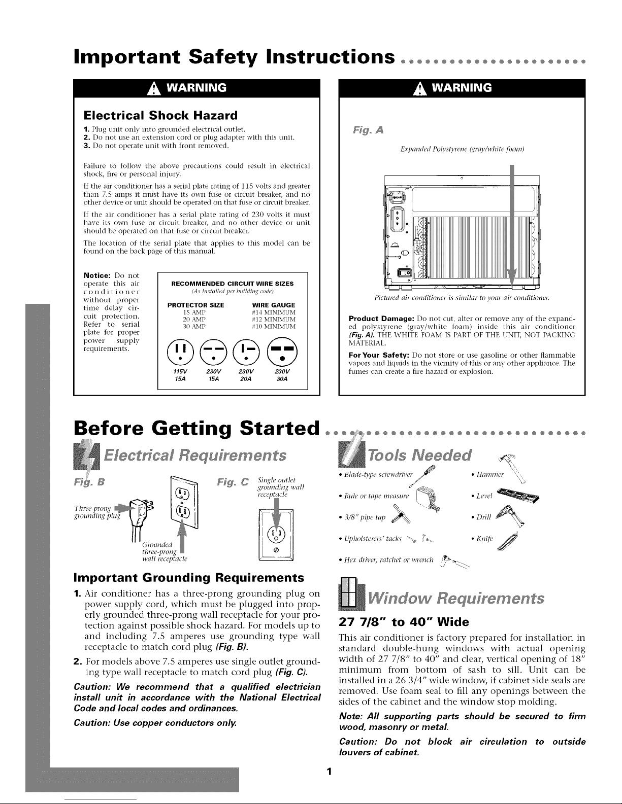
Hgo A
Expanded Polystyrem! (gray/white tbam)
Notice: Do not
operate this air
conditioner
without proper
time delay cir-
cuit protection.
Refer to serial
plate for proper
power supply
requireInents.
RECOMMENDED CIRCUIT WIRE SIZES
(As installed per blfildi_l,¢ co&)
PROTECTOR SIZE WIRE GAUGE
1S AMP #14 MINIMUM
20 AMP #12 MINIMUM
30 AMP # 10 MINIMUM
@©©@
115V 230V 230V 230V
15.4 15.4 20A 30A
Pictured air conditioner is similar to your air conditioner
Product Damage: Do not cut, alter or remove any of the expand-
ed polystyrene (gray/white foam) inside this air conditioner
(Fig. AL THE WHITE FOAM IS PART OF THE UNIT, NOT PACKING
MATERIAL,
For Your Safety: Do not store or use gasoline or other flaInmable
vapors and liquids in the vicinity of this or any other appliance. The
fumes can create a fire hazard or explosion.
Before Getting Started °°° °°°°°°°°°°°°°°°°°°°°°°°°°°o
Electrical Requ[yements
Thme-pro1_q
gmundingplug _
"" (;l'OllHddt
three-prong
wall receptacle
_o _ Single outlet
_#rolmdin_#wall
Important Grounding Requirements
1. Air conditioner has a three-prong grounding plug on
power supply cord, which must be plugged into prop-
erly grounded three-prong wall receptacle for your pro-
tection against possible shock hazard. For models up to
and including 7.5 amperes use grounding type wall
receptacle to match cord plug (Fig. B).
2. For models above 7.5 amperes use single outlet ground-
ing type wall receptacle to match cord plug (Fig. C).
Caution: We recommend that a qualified electrician
install unit in accordance with the National Electrical
Code and local codes and ordinances.
Caution: Use copper conductors only.
Window Requ[rements
27 718" to 40" Wide
This air conditioner is factory prepared for installation in
standard double-hung windows with actual opening
width of 27 7/8" to 40" and clear, vertical opening of 18"
minimum from bottom of sash to sill. Unit can be
installed in a 26 3/4" wide window, if cabinet side seals are
removed. Use foam seal to fill any openings between the
sides of the cabinet and the window stop molding.
Note: All supporting parts should be secured to firm
wood, masonry or metal
Caution: Do not block air circulation to outside
louvers of cabinet.
Installation°°°°°°°°°°°°°°°°°°°°°°°°°°°°°°°°°°°°°°°°°°°°°°°°
Decoraffve & ChassT RemovM
F_goD F_goE
Air filter
i SCI'PWS
0" _ Cabinet Chassis
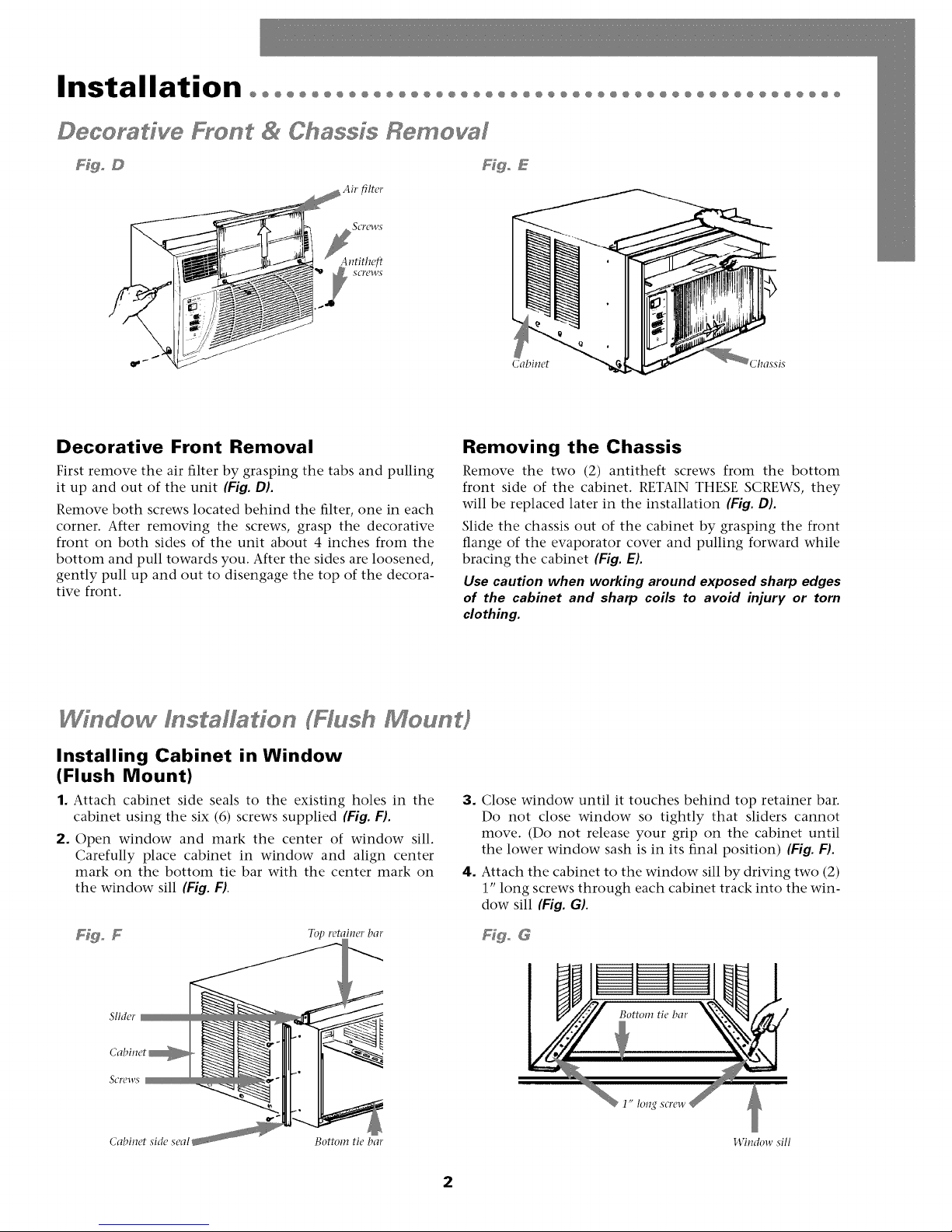
Decorative Front Removal
First remove the air filter by grasping the tabs and pulling
it up and out of the unit (Fig. DL
Remove both screws located behind the filter, one in each
corner. After removing the screws, grasp the decorative
front on both sides of the unit about 4 inches from the
bottom and pull towards you. After the sides are loosened,
gently pull up and out to disengage the top of the decora-
tive front.
Wfndow f staffaffon (Hash Mo n#
Installing Cabinet in Window
(Flush Mount)
1. Attach cabinet side seals to the existing holes in the
cabinet using the six (6) screws supplied (Fig. F).
2. Open window and mark the center of window sill.
Carefully place cabinet in window and align center
mark on the bottom tie bar with the center mark on
the window sill (Fig. FI.
Removing the Chassis
Remove the two (2) antitheft screws from the bottom
front side of the cabinet. RETAIN THESE SCREWS, they
will be replaced later in the installation {Fig. DL
Slide the chassis out of the cabinet by grasping the front
flange of the evaporator cover and pulling forward while
bracing the cabinet (Fig. E).
Use caution when working around exposed sharp edges
of the cabinet and sharp coils to avoid injury or torn
clothing.
3. Close window until it touches behind top retainer bar.
Do not close window so tightly that sliders cannot
move. (Do not release your grip on the cabinet until
the lower window sash is in its final position) {Fig. FL
4. Attach the cabinet to the window sill by driving two (2)
1" long screws through each cabinet track into the win-
dow sill (Fig. G).
SIMer
Cabinet
SCl'PWS
Cabinet side seal Bottom tie bar
Ffgo G
145ndow sill
2
Installation°°°°°°°°°°°°°°°°°°°°°°°°°°°°°°°°°°°°°°°°°°°°°°°°°°°°
Wi dew l staHade FHush Meu t)
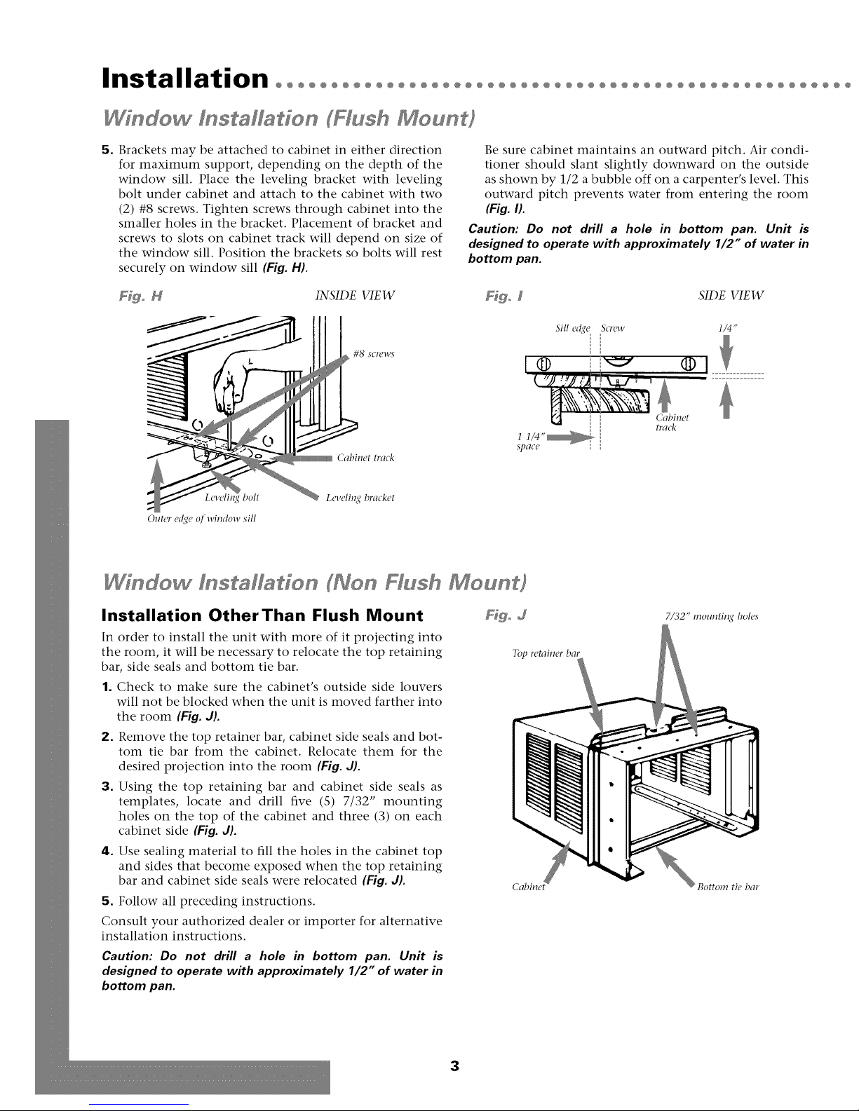
5. Brackets may be attached to cabinet in either direction
for maximum support, depending on the depth of the
window sill. Place the leveling bracket with leveling
bolt under cabinet and attach to the cabinet with two
(2) #8 screws. Tighten screws through cabinet into the
smaller holes in the bracket. Placement of bracket and
screws to slots on cabinet track will depend on size of
the window sill. Position the brackets so bolts will rest
securely on window sill (Fig. H).
Be sure cabinet maintains an outward pitch. Air condi-
tioner should slant slightly downward on the outside
as shown by 1/2 a bubble off on a carpenter's level. This
outward pitch prevents water from entering the room
(Fig. I).
Caution: Do not drill a hole in bottom pan. Unit is
designed to operate with approximately 1/2" of water in
bottom pan.
F@o N INSIDE VIEW Fdgo 5 SIDE VIEW
Sill e_qe Screw
Outer edge of window sill
bolt
#8 SCI'CWS
Cabinet track
Leveli1_q bracket
/i i _ l; i i_1 n
1 1/4"_
SpaCC
® .........
i',: . =_
Cabinet
Ira&
I/4"
Installation OtherThan Flush Mount
In order to install the unit with more of it projecting into
the room, it will be necessary to relocate the top retaining
bar, side seals and bottom tie bar.
1. Check to make sure the cabinet's outside side louvers
will not be blocked when the unit is moved farther into
the room (Fig. d).
2. Remove the top retainer bar, cabinet side seals and bot-
tom tie bar from the cabinet. Relocate them for the
desired projection into the room (Fig. d).
3. Using the top retaining bar and cabinet side seals as
templates, locate and drill five (S) 7/32" mounting
holes on the top of the cabinet and three (3) on each
cabinet side (Fig. J).
4. Use sealing material to fill the holes in the cabinet top
and sides that become exposed when the top retaining
bar and cabinet side seals were relocated (Fig. J).
5. Follow all preceding instructions.
Consult your authorized dealer or importer for alternative
installation instructions.
Caution: Do not drill a hole in bottom pan. Unit is
designed to operate with approximately 1/2" of water in
bottom pan.
Fdgo d
T(Q retainerbar
7/32" mounting boles
Bottom tie bar
3
@@@@@@@@@@@@@@@@@@@@@@@@@@@@@@@@@@@@@@@@@@@@@@@@@@@@@@@@@@@@@@@@@@@
Filler P3 el f s Mf3ffo
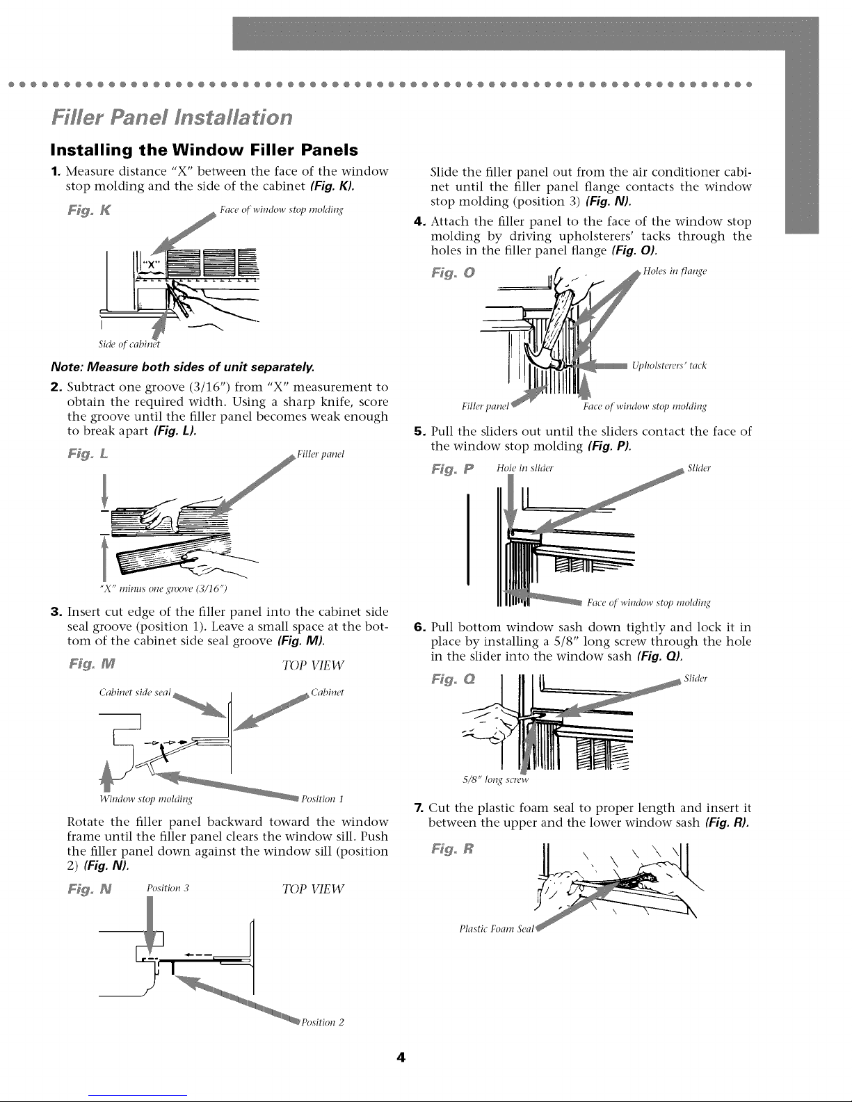
Installing the Window Filler Panels
1. Measure distance "X" between the face of the window
stop molding and the side of the cabinet (Fig. K).
Fig_ K Face o[ window stop molding
Side o[ cabinet
Note: Measure both sides of unit separately.
2. Subtract one groove (3/16") from "X" measurement to
obtain the required width. Using a sharp knife, score
the groove until the filler panel becomes weak enough
to break apart (Fig. L).
Fig° L Fillerpanel
Slide the filler panel out from the air conditioner cabi-
net until the filler panel flange contacts the window
stop molding (position 3) (Fig. NL
4. Attach the filler panel to the face of the window stop
molding by driving upholsterers' tacks through the
holes in the filler panel flange (Fig. OL
Ffgo 0 _ _Holes in flange
5. Pull the sliders out until the sliders contact the face of
the window stop molding (Fig. PL
F_go _ Hole in slider Slider
Upholsterers j tack
Fillet' panel Face of-window stop rooMing
"X j" minus one 2(roove (3/16'9
3. Insert cut edge of the filler panel into the cabinet side
seal groove (position 1). Leave a small space at the bot-
tom of the cabinet side seal groove (Fig. ML
Fig° M TOP VIEW
Wimlow stop moldin2(
Rotate the filler panel backward toward the window
frame until the filler panel clears the window sill. Push
the filler panel down against the window sill (position
2) (Fig. N).
Fig. _ Position 3 TOP VIEW
_--mm
Face of window stop rooMing
6. Pull bottom window sash down tightly and lock it in
place by installing a 5/8" long screw through the hole
in the slider into the window sash (Fig. OL
Figo G Sli,let'
5/8" long screw
7. Cut the plastic foam seal to proper length and insert it
between the upper and the lower window sash (Fig. R}.
Figo R \ \ \\\
Plastic Foam Seal
4
Installation°°°°°°°°°°°°°°°°°°°°°°°°°°°°°°°°°°°°°°°°°°°°°°°°°°°°
Ffffer P3 el f sta/f3do
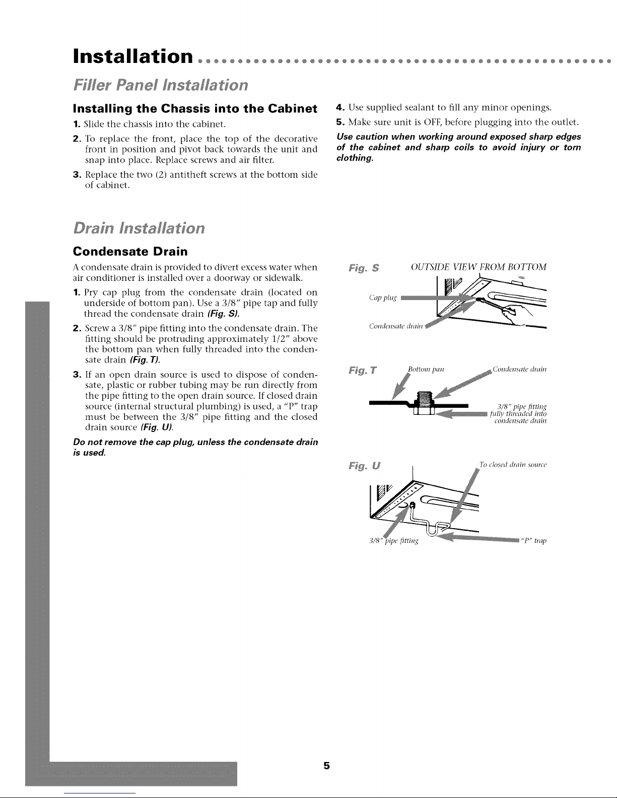
Installing the Chassis into the Cabinet
1. Slide the chassis into the cabinet.
2. To replace the front, place the top of the decorative
front in position and pivot back towards the unit and
snap into place. Replace screws and air filter.
3. Replace the two (2) antitheft screws at the bottom side
of cabinet.
Drafn Instalfadon
Condensate Drain
A condensate drain is provided to divert excess water when
air conditioner is installed over a doorway or sidewalk.
1. Pry cap plug from the condensate drain (located on
underside of bottom pan). Use a 3/8" pipe tap and fully
thread the condensate drain (Fig. S).
2. Screw a 3/8" pipe fitting into the condensate drain. The
fitting should be protruding approximately 1/2" above
the bottom pan when fully threaded into the conden-
sate drain (Fig. T).
3. If an open drain source is used to dispose of conden-
sate, plastic or rubber tubing may be run directly from
the pipe fitting to the open drain source. If closed drain
source (internal structural plumbing) is used, a "P" trap
must be between the 3/8" pipe fitting and the closed
drain source (Fig. U).
Do not remove the cap plug, unless the condensate drain
is used.
4. Use supplied sealant to fill any minor openings.
5. Make sure unit is OFF, before plugging into the outlet.
Use caution when working around exposed sharp edges
of the cabinet and sharp coils to avoid injury or torn
clothing.
OUTSIDE VIEW FROM BOTTOM
Cap plug
3/8" t)ipe fittiug
fiflly threaded into
COIldCIISatP drain
5
@@@@@@@@@@@@@@@@@@@@@@@@@@@@@@@@@@@@@@@@@@@@@@@@@@@@@@@@@@@@@@@@@@@
T rougho heoWaff I s affado
This air conditioner is designed as a slide-out type chassis,
making it possible to install it through-the-wall in both exist-
ing and new construction. We recommend that this type of
installation be performed with professional assistance.
IMPORTANT: This appliance must be installed according to
all applicable electrical and building codes and ordinances.
It is recommended that you have help to install your unit
and that you use proper lifting technique to avoid per-
sonal injury.
It is important that you inspect the condition of the wall
where the air conditioner will be installed. Be sure the wall
can support the weight of the unit.
All cabinet louvers MUST BE on the outdoor side of the
wall. DO NOT BLOCK SIDE LOUVERS.
The cabinet must be installed level from side-to-side and
with a downward tilt from inside to outside.
DO NOT USE AN EXTENSION CORD: Make certain a
proper electrically sized wall receptacle is available close to
the unit. If not, make arrangements to install one.
If the air conditioner has a serial plate rating of 115 volts
and greater than 7.5 amps it must have its own fuse or cir-
cuit breaker, and no other device or unit should be oper-
ated on that fuse or circuit breaker.
If the air conditioner has a serial plate rating of 230 volts it
must have its own fuse or circuit breaker, and no other device
or unit should be operated on that fuse or circuit breaker.
1. First remove the Decorative front panel and chassis
from the cabinet. Remove top and side retainer bars
from the cabinet (see page 2).
2. Determine the size of the opening for a wood frame by
adding 1/8" to the width and height of the cabinet.
Measure height from top of cabinet to bottom of bar.
Add this measurement to the thickness of wood used to
build the frame. This will determine the size of wall
opening needed. Minimum 1" thick lumber is recom-
mended when building the frame. When determining
finish frame thickness, be sure not to cover side louvers
on the cabinet.
3. Install the finished frame in the wall opening square
and level, nail or screw it securely to the wall and place
the cabinet into the framed wall opening.
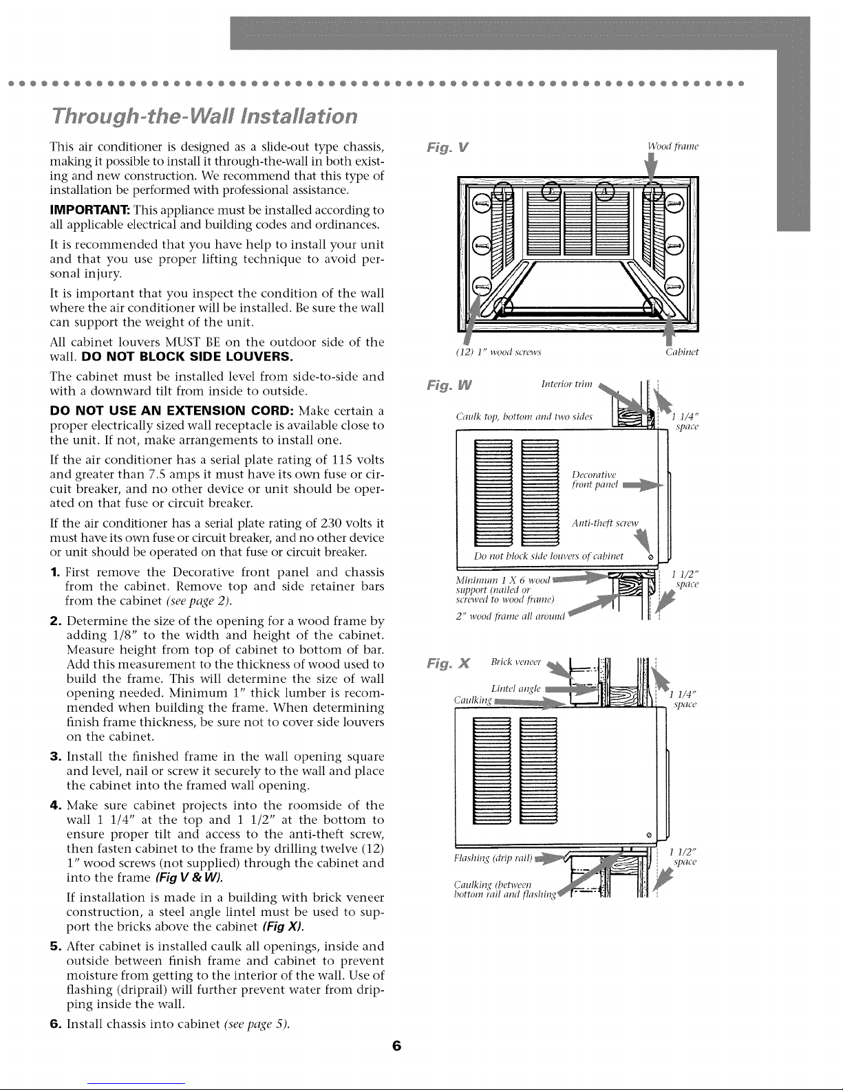
4. Make sure cabinet projects into the roomside of the
wall 1 1/4" at the top and 1 1/2" at the bottom to
ensure proper tilt and access to the anti-theft screw,
then fasten cabinet to the frame by drilling twelve (12)
1" wood screws (not supplied) through the cabinet and
into the frame (Fig V & W).
If installation is made in a building with brick veneer
construction, a steel angle lintel must be used to sup-
port the bricks above the cabinet (Fig XL
5. After cabinet is installed caulk all openings, inside and
outside between finish frame and cabinet to prevent
moisture from getting to the interior of the wall. Use of
flashing (driprail) will further prevent water from drip-
ping inside the wall.
6. Install chassis into cabinet (see page 5).
6
(12) 1" wood screws
Fd_ _ Interior trim
Caulk top, bottom and two sides
Anti-theft screw
Do not block sMe louvers of cabinet
Minimum 1
support (nailed or
screwed to wood fi'ame)
2" wood fi'ame all around
Fdgo X Brick ve,eer
Lintel al_(le
Calflkin
Flashin
Caulkin,¢ (bel-weeu
bottom rail and flashing
Cabinet
Operation°°°°°°°°°°°°°°°°°°°°°°°°°°°°°°°°°°°°°°°°°°°°°°°°°°°°•
Electmnfc Central Panel
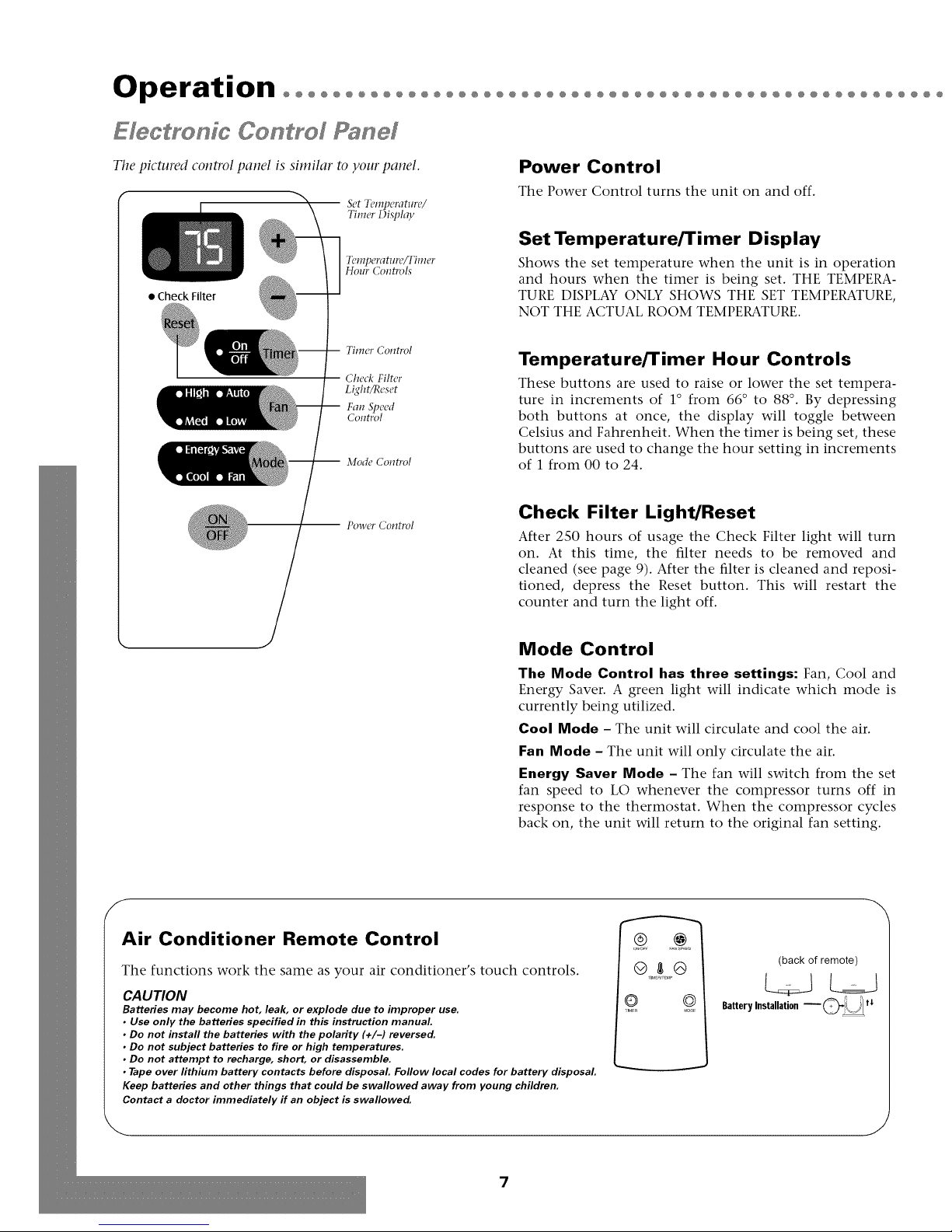
Tile pictured control panel is similar to your panel.
Set Temperature/
Timer i)iqflay
TL!lllpPl'f?tlll'P/TllllPl'
Hour Controls
• Check Filter
Timer Control
Check Filter
Light/Reset
Fan Speed
Control
Mode Control
-- Power Control
Power Control
The Power Control turns the unit on and off.
Set Temperature/Timer Display
Shows the set temperature when the unit is in operation
and hours when the timer is being set. THE TEMPERA-
TURE DISPLAY ONLY SHOWS THE SET TEMPERATURE,
NOT THE ACTUAL ROOM TEMPERATURE.
Temperature/Timer Hour Controls
These buttons are used to raise or lower the set tempera-
ture in increments of 1 ° from 66 ° to 88 °. By depressing
both buttons at once, the display will toggle between
Celsius and Fahrenheit. When the timer is being set, these
buttons are used to change the hour setting in increments
of 1 from 00 to 24.
Check Filter Light/Reset
After 2S0 hours of usage the Check Filter light will turn
on. At this time, the filter needs to be removed and
cleaned (see page 9). After the filter is cleaned and reposi-
tioned, depress the Reset button. This will restart the
counter and turn the light off.
Mode Control
The Mode Control has three settings: Fan, Cool and
Energy Saver. A green light will indicate which mode is
currently being utilized.
Cool Mode - The unit will circulate and cool the air.
Fan Mode - The unit will only circulate the air.
Energy Saver Mode - The fan will switch from the set
fan speed to LO whenever the compressor turns off in
response to the thermostat. When the compressor cycles
back on, the unit will return to the original fan setting.
f
Air Conditioner Remote Control
The functions work the same as your air conditioner's touch controls.
CAUTION
Batteries may become hot, leak, or explode clue to improper use.
• Use only the batteries specified in this instruction manual
• Do not install the batteries with the polarity (+11-) reversed.
• Do not subject batteries to fire or high temperatures.
• Do not attempt to recharge, short, or disassemble.
• Tape over lithium battery contacts before disposal Follow local codes for battery disposal
Keep batteries and other things that could be swallowed away from young children.
Contact a doctor immediately if an object is swallowed.
@l@
@ @
,IMER _O,X
(back of remote)
BatteryInstallation _J/\_/
J
7

@@@@@@@@@@@@@@@@@@@@@@@@@@@@@@@@@@@@@@@@@@@@@@@@@@@@@@@@@@@@@@@@@@@
Fyon Panel
Fan Speed Control
The Fan Speed Control has four settings: High,
Medium, Low and Auto. The settings are adjusted with the
Fan Speed Control, each time the button is depressed it
changes the setting. A green light will indicate which set-
ting is currently being used.
When the Auto feature is selected while the air condition-
er is in the COOL mode, the fan speeds will change auto-
matically as the temperature in the room changes.
• 7° or more above the set temperature will use HI fan.
• 4 ° - 7 ° above the set temperature will use MED fan.
• 4 ° or less above the set temperature will use LO fan.
Timer Control
The timer can be set to either turn the unit on or off.
To turn the unit on using theTimer:
Depress the timer key when the power is off, the display
will read 00. Adjust to the desired number of hours before
TURN ON using the up/down arrows.
The display will show the time by hours left until TURN
ON.
To turn the timer off, depress the timer key
A green light next to the Timer Control indicates that the
timer is set.
Directing Airflow
Unit is engineered with adjustable louvers to direct dis-
charge airflow. Louvers are manually adjusted by moving
levers in direction of desired airflow (Fig. YI.
To turn the unit OFF using theTimer.
Depress the timer key when the power is on, the display will
read 00. Adjust to the desired number of hours before TURN
OFF using the up/down arrows. The display will automati-
cally go back to the set temperature after ]0 seconds.
To display the amount of time left until TURN OFF,
depress the timer button once.
To turn the TIMER OFF, depress the timer button twice.
A green light next to the Timer Control indicates that the
timer is set.
Built-in three minute timing delay.
This electronic controlled unit will not automatically
resume operation after a power failure.
ff this electric unit will not respond to touch pad or
remote control commands, it is necessary to unplug the
unit from the electrical outlet for five seconds and then
plug the unit back in.
8
Maintenance°°°°°°°°°°°°°°°
°00°°00°00°°00°00°000°00°00°°00
Cleaning Air Filter
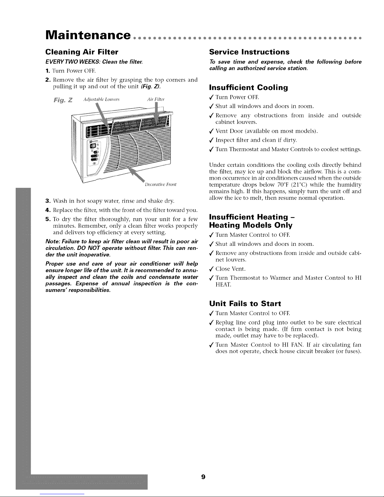
EVERY TWO WEEKS: Clean the filter.
1. Turn Power OFF.
2. Remove the air filter by grasping the top corners and
pulling it up and out of the unit (Fig. Z).
_ _ Adjustabk' Lo_n,ers Air Filter
Decorative Front
3. Wash in hot soapy water, rinse and shake dry.
4. Replace the filter, with the front of the filter toward you.
5. To dry the filter thoroughly, run your unit for a few
minutes. Remember, only a clean filter works properly
and delivers top efficiency at every setting.
Note: Failure to keep air filter clean will result in poor air
circulation. DO NOT operate without filter. This can ren-
der the unit inoperative.
Proper use and care of your air conditioner will help
ensure longer life of the unit. It is recommended to annu-
ally inspect and clean the coils and condensate water
passages. Expense of annual inspection is the con-
sumers" responsibilities.
Service Instructions
To save time and expense, check the following before
calling an authorized service station.
Insufficient Cooling
1" Turn Power OFF.
1" Shut all windows and doors in room.
1" Remove any obstructions from inside and outside
cabinet louvers.
1" Vent Door (available on most models).
1" Inspect filter and clean if dirty.
1" Turn Thermostat and Master Controls to coolest settings.
Under certain conditions the cooling coils directly behind
the filter, may ice up and block the airflow. This is a com-
mon occurrence in air conditioners caused when the outside
temperature drops below 70°F (21°C) while the humidity
remains high. If this happens, simply turn the unit off and
allow the ice to melt, then resume normal operation.
Insufficient Heating-
Heating Models Only
1" Turn Master Control to OFF.
1" Shut all windows and doors in room.
1" Remove any obstructions from inside and outside cabi-
net louvers.
1" Close Vent.
1" Turn Thermostat to Warmer and Master Control to HI
HEAT.
Unit Fails to Start
1" Turn Master Control to OFF.
1" Replug line cord plug into outlet to be sure electrical
contact is being made. (If firm contact is not being
made, outlet may have to be replaced).
1" Turn Master Control to HI FAN. If air circulating fan
does not operate, check house circuit breaker (or fuses).
9
 Loading...