

Page 1
For Future Reference
Write down the model and serial numbers
The model and serial numbers can be
found on the left hand side of the decora-
tive front grille. Use these numbers in any
correspondence or service calls concerning
your air conditioner.
Para referencia futura
Anote los numeros de modelo y series
Encontrar_ los nfimeros de modelos y series en la mano
izquierda del panel decorativo. Use estos numeros en
cualqmer correspondencia o llamadas de servicio respecto
a su aire acondicionado.
Room Air Conditioners for
Double-Hung Windows
Acondicionadores de aire
ambientales para ventanas
de guillotina
Climatiseur d' air individuel
pour fenOtres h guillotine
m
Pour r6f6rence ult6rieure
Inscrire les numeros de modele et de serie
On trouvera les num6ros de mod6le et de s6rie sur le c6t6
gauche du panneau d6coratif. Utiliser ces num6ros dans
toute correspondance ou tout appel d'entretien au sujet de
son climatiseur.
Model No.. Modelo No,. N °de modOh
Date of Pulvhase, Fecha de la compra, Date d2_chat
@@ @@
@_u_i_i_ i}Z {77;_¸ x ¸:7¸¸¸¸
@
@
@
@
@
Keep_hese instructions for future reference
@
@
@
@
For additional questions please call: ;
866-MAYTAG 1 ;,
@
MAYIAG
@
@
@
@
@
@
@
Page 2
Important Safety Instructions ooooooooooooooooooooooo
Electrical Shock Hazard
1. Plug unit only into grounded electrical outlet.
2. Do not use an extension cord or plug adapter with this unit.
3. Do not operate unit with front removed.
Failure to follow the above precautions could result in electrical
shock, fire or personal injury.
If the air conditioner has a serial plate rating of 11S volts and up to
and including 7.S amps the unit may be on a fuse or circuit breaker
with other devices. Howevel, the maximum amps of all devices on
that fuse or circuit breaker can not exceed the amps of the filse or
circuit breaker.
If the air conditioner has a serial plate rating ofllS volts and greater
than 7.5 amps it must have its own fuse or circuit breaker, and no
other device or unit should be operated oil that fuse or circuit breaker.
If the air conditioner has a serial plate rating of 230 volts it nmst
have its own fuse or circuit breaker, and no other device or unit
should be operated on that fuse or circuit breaker.
Tile location of tile serial plate that applies to this inodel can be
found on the front page of this Inanual.
Hgo A
Expanded Polystyrene (gray/white tbam)
o
Notice: Do not
operate this air
conditioner
without proper
tiIne delay cir-
cuit protection.
Refer to serial
plate for proper
power supply
requireInents.
RECOMMENDED CIRCUIT WIRE SIZES
?As i_Oall_ d p_ r buildi_g co&)
PROTECTOR SIZE WIRE GAUGE
1S AMP #14 MINIMUM
20 AMP #12 MINIMUM
30 AMP #10 MINIMUM
@©©@
115V 230V 230V 230V
15.4 15.4 20A 30A
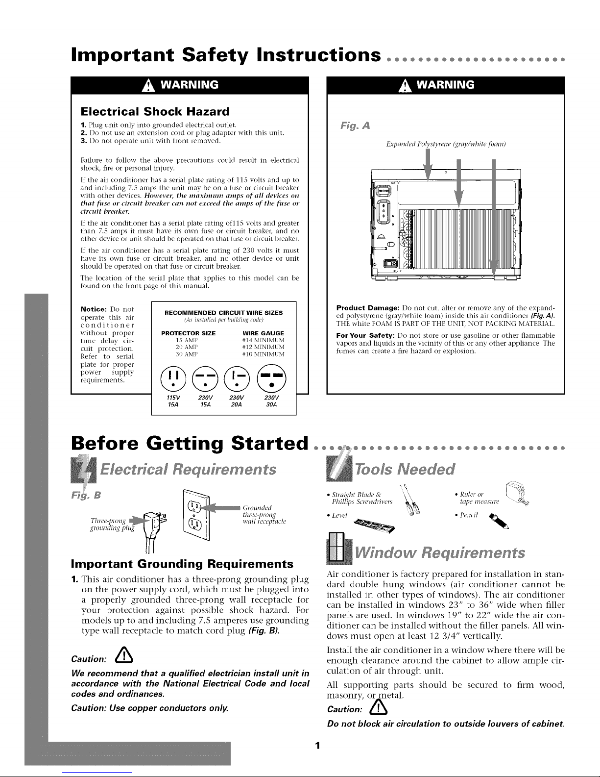
Product Damage: Do not cut, alter or remove any of tile expand-
ed polystyrene (gray/white foam) inside this air conditioner (Fig. AL
THE white FOAM IS PART OF THE UNIT, NOT PACKING MATERIAL.
For Your Safety: Do not store or use gasoline or other flaInmable
vapors and liquids in the vicinity of this or any other appliance. The
fumes can create a fire hazard or explosion.
Before Getting Started ooo ooooooooooooooooooooooooooo
Electrical Requfrements
Important Grounding Requirements
1. This air conditioner has a three-prong grounding plug
on the power supply cord, which must be plugged into
a properly grounded three-prong wall receptacle for
your protection against possible shock hazard. For
models up to and including 7.5 amperes use grounding
type wall receptacle to match cord plug (Fig. B).
Caution: &
We recommend that a qualified electrician instafl unit in
accordance with the National Electrical Code and local
codes and ordinances.
Caution: Use copper conductors only.
TooJs Needed
• Straight Blade & • Ruler or
Phillips &:rewdrivers tape measure
• Level • Pencil
Wfndew Requfrements
Air conditioner is factory prepared for installation in stan-
dard double hung windows (air conditioner cannot be
installed in other types of windows). The air conditioner
can be installed in windows 23" to 36" wide when filler
panels are used. In windows 19" to 22" wide the air con-
ditioner can be installed without the filler panels. All win-
dows must open at least 12 3/4" vertically.
Install the air conditioner in a window where there will be
enough clearance around the cabinet to allow ample cir-
culation of air through unit.
All supporting parts should be secured to firm wood,
masonry, or metal.
Caution: &
Do not block air circulation to outside louvers of cabinet.
Page 3
Installation°°°°°°°°°°°°°°°°°°°°°°°°°°°°°°°°°°°°°°°°°°°°°°°°
Wi dew I staHatie
Parts List
Electronic Cabinet
Control Panel
Filter
Filler Panel
Filler Panel Installation
1. Place tabbed side (Fig°C} of curtain in tracks on side of
air conditioner cabinet, and slide down the tracks until
the curtain is even top and bottom (Fig. DL
_o C Tal,bed E_{4e _o _ Lock Eg{{e
installation in window
23" to 36" wide
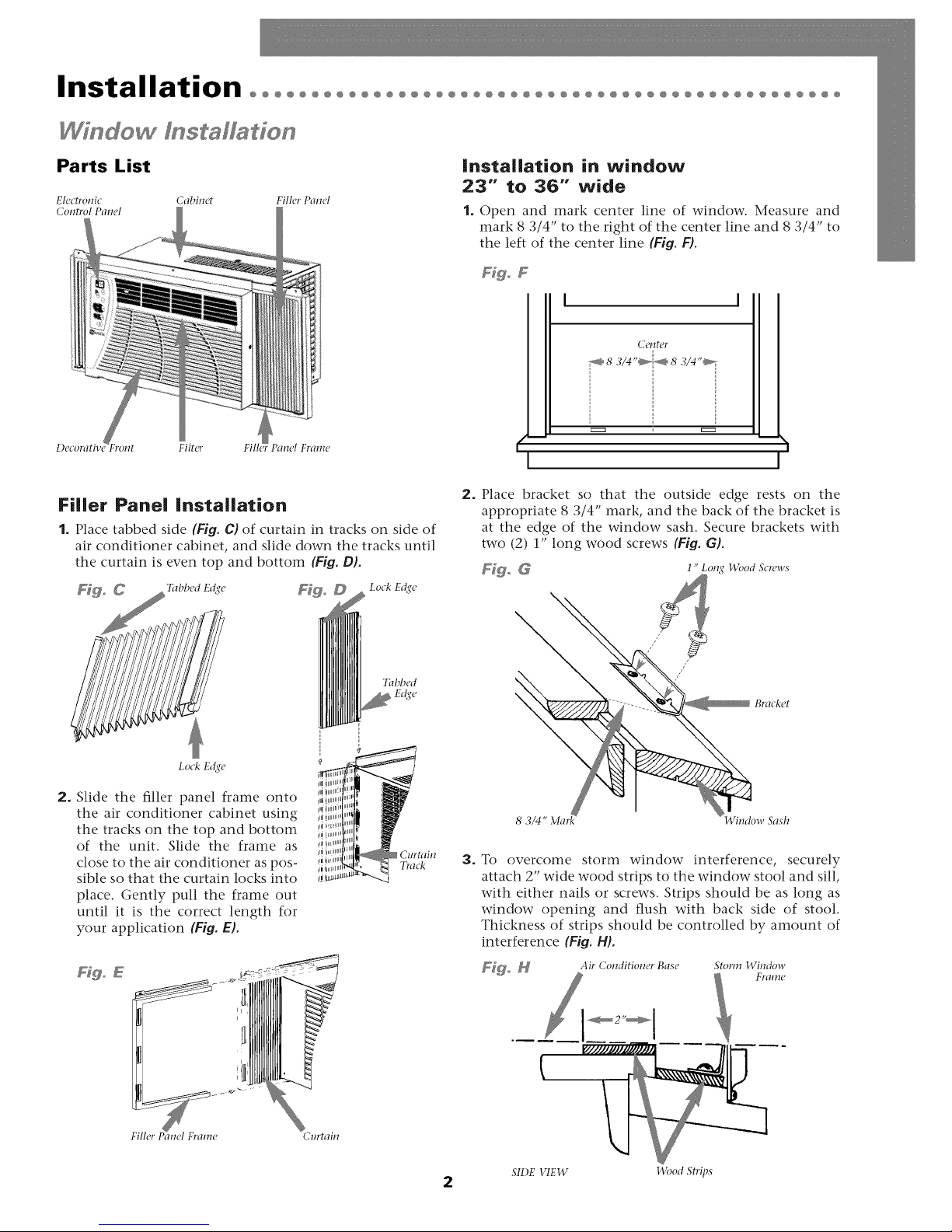
1. ()pen and mark center line of window. Measure and
mark 8 3/4" to the right of the center line and 8 3/4" to
the left of the center line (Fig. FL
Fig° F
I I
Co, ltcr
_8 3/4"_8 3/4"_-
m m
( i
I I
2. Place bracket so that the outside edge rests on the
appropriate 8 3/4" mark, and the back of the bracket is
at the edge of the window sash. Secure brackets with
two (2) 1" long wood screws (Fig. G).
F_ G 1" Long 14_)od Screws
Lock E_(e
2. Slide the filler panel frame onto
the air conditioner cabinet using
the tracks on the top and bottom
of the unit. Slide the frame as
close to the air conditioner as pos-
sible so that the curtain locks into
place. Gently pull the frame out
until it is the correct length for
your application (Fig. E).
Hgo E
Tabbed
Cm'tain
Track
3. To overcome storm window interference, securely
attach 2" wide wood strips to the window stool and sill,
with either nails or screws. Strips should be as long as
window opening and flush with back side of stool.
Thickness of strips should be controlled by amount of
interference (Fig. 14).
_o _ Air Conditioner Base Storm l/gindow
Fralrle
2
SIDE VIEW Wood Strips
Page 4
Installation°°°°°°°°°°°°°°°°°°°°°°°°°°°°°°°°°°°°°°°°°°°°°°°°
Window Dstal don
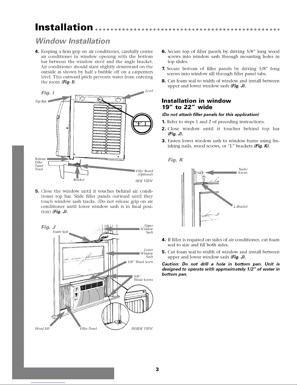
4. Keeping a firm grip on air conditioner, carefully center
air conditioner in window opening with the bottom
bar between the window stool and the angle bracket.
Air conditioner should slant slightly downward on the
outside as shown by half a bubble off on a carpenters
level. This outward pitch prevents water from entering
the room (Fig. I).
Bottom
Filh, r
Panel
Track
Fillet' Board
(Optional)
SIDE _qEW
5. Close the window until it touches behind air condi-
tioner top bar. Slide filler panels outward until they
touch window sash tracks. (Do not release grip on air
conditioner until lower window sash is in final posi-
tion) (Fig. J).
6. Secure top of filler panels by driving 5/8" long wood
screws into window sash through mounting holes in
top slides.
7. Secure bottom of filler panels by driving S/8" long
screws into window sill through filler panel tabs.
8. Cut foam seal to width of window and install between
upper and lower window sash (Fig. J).
Installation in window
19" to 22" wide
(Do not attach filler panels for this application)
1. Refer to steps 1 and 2 of preceding instructions.
2. Close window until it touches behind top bar
(Fig. J).
3. Fasten lower window sash to window frame using fin-
ishing nails, wood screws, or "L" brackets (Fig. K).
FfgoK
Nails/
L-Bracket
!4{md ,Sill Filler Panel INSIDE VIEW
Lower
!ATitldow
Sash
5/8" Wood Screw
I 5/,_"
Wood Screws
4. If filler is required on sides of air conditioner, cut foam
seal to size and fill both sides.
5. Cut foam seal to width of window and install between
upper and lower window sash {Fig. J).
Caution: Do not drill a hole in bottom pan. Unit is
designed to operate with approximately 1/2" of water in
bottom pan.
3
Page 5
@@@@@@@@@@@@@@@@@@@@@@@@@@@@@@@@@@@@@@@@@@@@@@@@@@
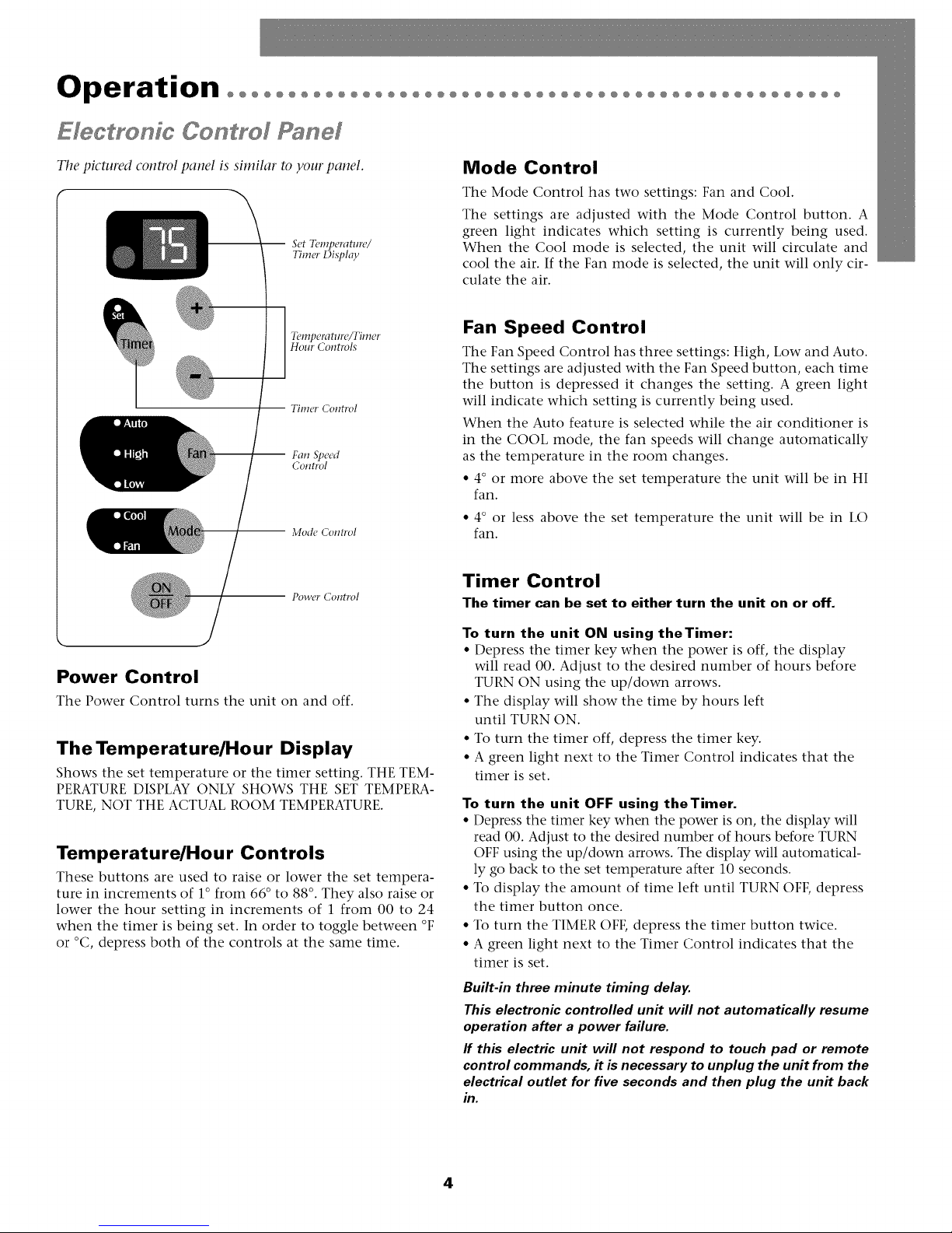
Mode Control
The Mode Control has two settings: Fan and Cool.
The settings are adjusted with the Mode Control button. A
Set Temperature/
Timer Disph_y
green light indicates which setting is currently being used.
When the Cool mode is selected, the unit will circulate and
cool the air. If the Fan mode is selected, the unit will only cir-
culate the air.
Temperature/Timer
Hour Controls
TIIll_T Colltrol
-- Fan Speed
Control
-- Mode Con_'ol
-- Power Control
Power Control
The Power Control turns the unit on and off.
The Temperature/Hour Display
Shows the set temperature or the timer setting. THE TEM-
PERATURE DISPLAY ONLY SHOWS THE SET TEMPERA-
TURE, NOT THE ACTUAL ROOM TEMPERATURE.
Temperature/Hour Controls
These buttons are used to raise or lower the set tempera-
ture in increments of 1° from 66 ° to 88 °. They also raise or
lower the hour setting in increments of 1 from 00 to 24
when the timer is being set. In order to toggle between °F
or °C, depress both of the controls at the same time.
Fan Speed Control
The Fan Speed Control has three settings: High, Low and Auto.
The settings are adjusted with the Fan Speed button, each time
the button is depressed it changes the setting. A green light
will indicate which setting is currently being used.
When the Auto feature is selected while the air conditioner is
in the COOL mode, the fan speeds will change automatically
as the temperature in the room changes.
• 4° or more above the set temperature the unit will be in HI
fan.
• 4° or less above the set temperature the unit will be in LO
fan.
Timer Control
The timer can be set to either turn the unit on or off.
To turn the unit ON using theTimer:
• Depress the timer key when the power is off, the display
will read 00. Adjust to the desired number of hours before
TURN ON using the up/down arrows.
• The display will show the time by hours left
until TURN ON.
• To turn the timer off, depress the timer key.
• A green light next to the Timer Control indicates that the
timer is set.
To turn the unit OFF using theTimer.
• Depress the timer key when the power is on, the display will
read 00. Adjust to the desired number of hours before TURN
OFF using the up/down arrows. The display will automatical-
ly go back to the set temperature after 10 seconds.
• To display the amount of time left until TURN OFF, depress
the timer button once.
• To turn the TIMER OFF, depress the timer button twice.
• A green light next to the Timer Control indicates that the
timer is set.
Built-in three minute timing delay.
This electronic controlled unit will not automatically resume
operation after a power failure.
ff this electric unit will not respond to touch pad or remote
control commands, it is necessary to unplug the unit from the
electrical outlet for five seconds and then plug the unit back
in.
4
Page 6
Operation°°°°°°°°°°°°°°°°°°°°°°°°°°°°°°°°°°°°°°°°°°°°°°°°°°
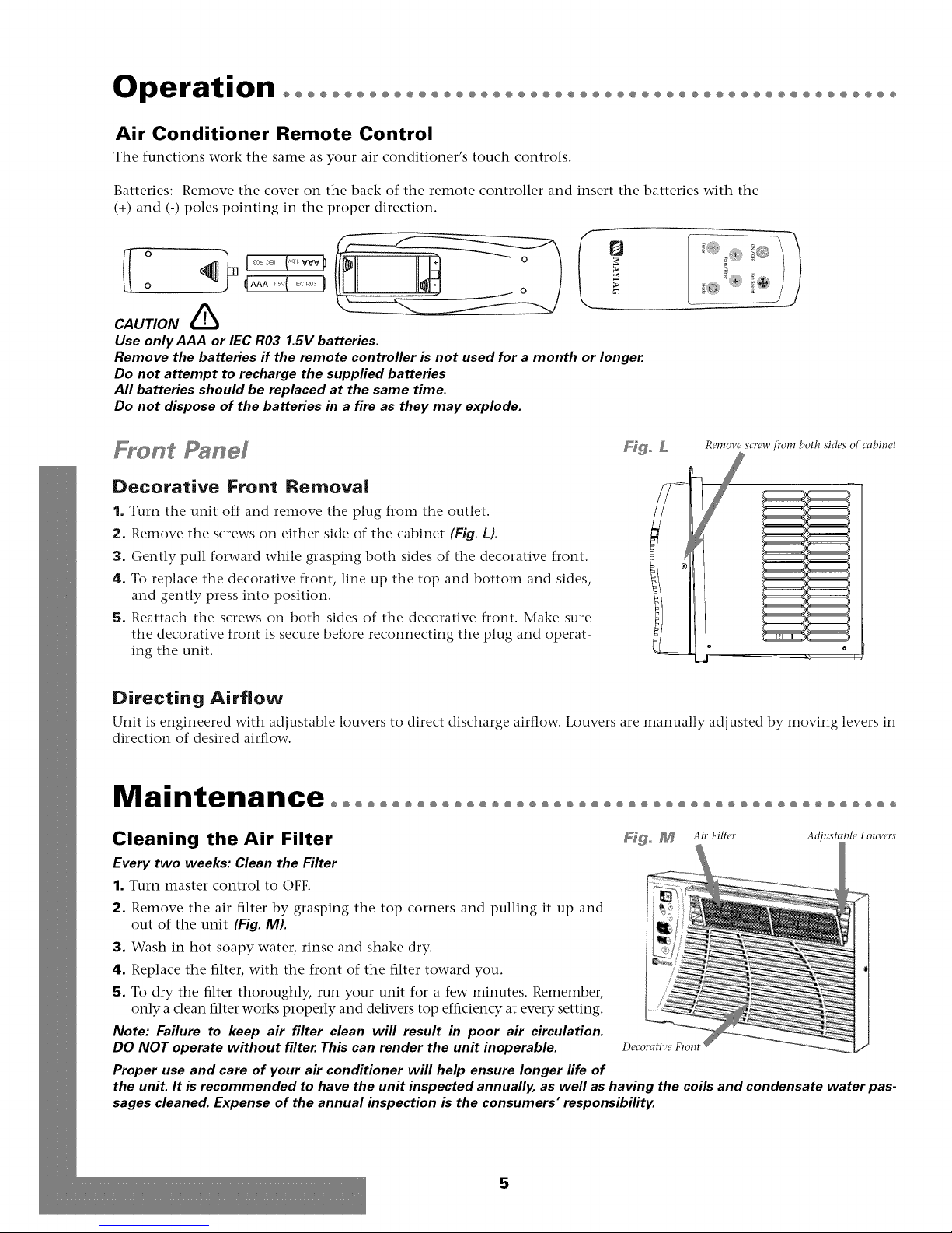
Air Conditioner Remote Control
The functions work the same as your air conditioner's touch controls.
Batteries: Remove the cover on the back of the remote controller and insert the batteries with the
(+) and (-) poles pointing in the proper direction.
CAUTION
Use only AAA or IEC R03 1.5V batteries.
Remove the batteries if the remote controller is not used for a month or longer
Do not attempt to recharge the supplied batteries
All batteries should be replaced at the same time.
Do not dispose of the batteries in a fire as they may explode.
Panel
Ffgo L
Remove screw _'om both sides of cabinet
Decorative Front Removal
1. Turn the unit off and remove the plug from the outlet.
2. Remove the screws on either side of the cabinet (Fig. i).
3. Gently pull forward while grasping both sides of the decorative front.
4. To replace the decorative front, line up the top and bottom and sides,
and gently press into position.
5. Reattach the screws on both sides of the decorative front. Make sure
the decorative front is secure before reconnecting the plug and operat-
ing the unit.
Directing Airflow
Unit is engineered with adjustable louvers to direct discharge airflow. Louvers are manually adjusted by moving levers in
direction of desired airflow.
Maintenance°°°°°°°°°°°°°°°°°°°°°°°°°°°°°°°°°°°°°°°°°°°°°°
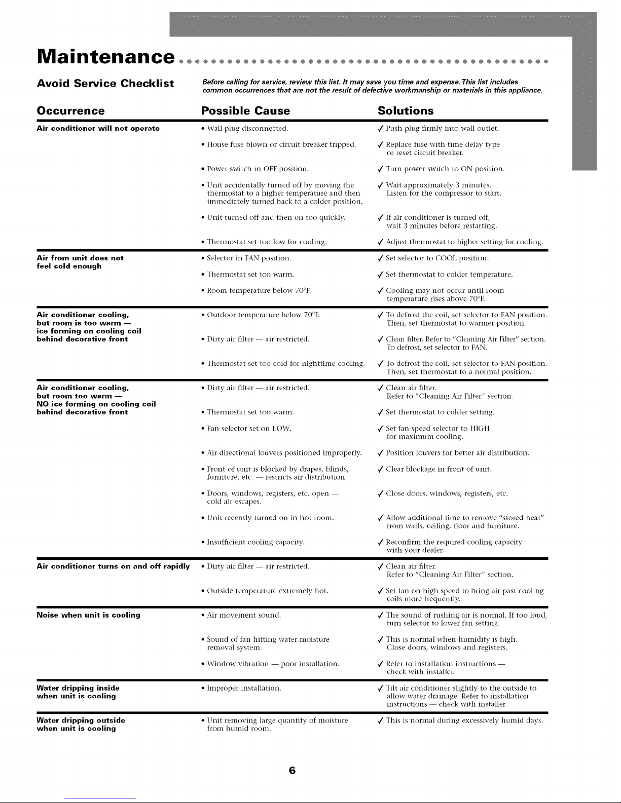
Cleaning the Air Filter F_goM A_,.s.te,. A,_,,_t,.,_.Lo.v_.,_
Every two weeks: Clean the Filter
1. Turn master control to OFF.
2. Remove the air filter by grasping the top corners and pulling it up and
out of the unit (Fig. M).
3. Wash in hot soapy water, rinse and shake dry.
4. Replace the filter, with the front of the filter toward you. _1
5. To dry the filter thoroughly, run your unit for a few minutes. Remember,
only a clean filter works properly and delivers top efficiency at every setting.
Note: Failure to keep air filter clean will result in poor air circulation.
DO NOT operate without filter This can render the unit inoperable. Decorative Front /
Proper use and care of your air conditioner will help ensure longer life of
the unit. It is recommended to have the unit inspected annually, as well as having the coils and condensate water pas-
sages cleaned. Expense of the annual inspection is the consumers" responsibility.
5
Page 7
Maintenance°°°°°°°°°°°°°°°°°°°°°°°°°°°°°°°°°°°°°°°°°°°°°°
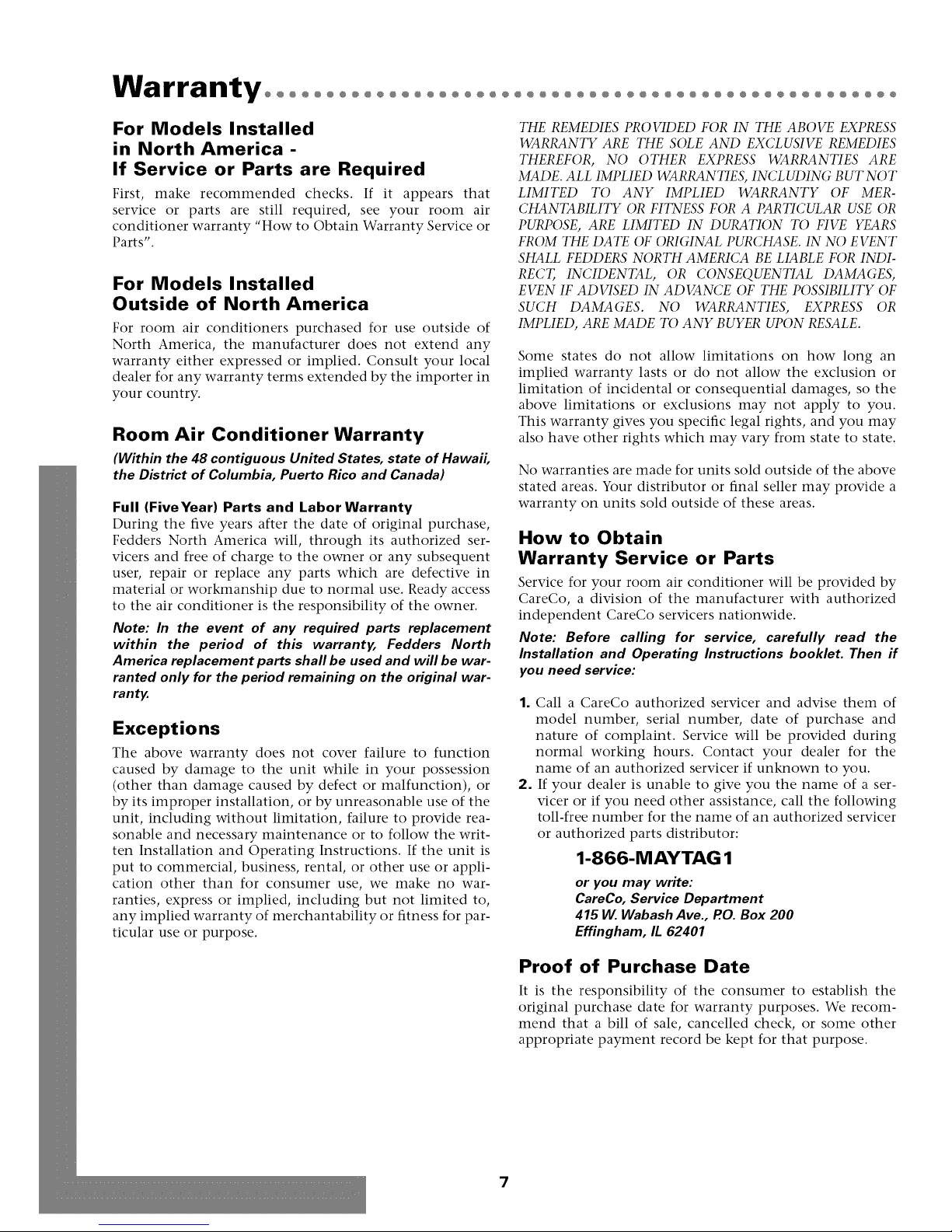
Avoid Service Checklist
Before calling for service, review this/isL It may save you time and expense. This fist includes
common occurrences that are not the result of defective workmanship or materials in this appliance.
Occurrence Possible Cause Solutions
Air conditioner will not operate • Wall plug disconnected,
• House fuse blown or circuit breaker tripped,
• Power switch in OFF position. v/ Turn power switch to ON position.
• Unit accidentally turned off by moving the _/Wait approximately 3 minutes,
thermostat to a higher temperature and then Listen for the compressor to start.
imlnediately turned back to a colder position.
• Unit turned off and then on too quickly. _/If air conditioner is turned off,
• TherInostat set too low- for cooling, _/Adjust thermostat to higher setting for cooling.
Air from unit does not
feel cold enough
Air conditioner cooling,
but room is too warm --
ice forming on cooling coil
behind decorative front
Air conditioner cooling,
but room too warm --
NO ice forming on cooling coil
behind decorative front
• Selector in FAN position.
• Wherlnostat set too warm.
• Room temperature below 70°E v/ Cooling may not occur until room
• Outdoor temperature below 70°E
• Dirty air filter -- air restricted.
• TherInostat set too cold for nighttime cooling. _/To defrost tile coil, set selector to FAN position.
• Dirty air filter -- air restricted.
• Therlnostat set too wartn.
• Fan selector set on LOW.
• Air directional louvers positioned improperly. _/Position louvers for better air distribution.
• Front of unit is blocked by drapes, blinds,
furniture, etc. -- restricts air distribution.
• Doors, windows, registers, etc. open --
cold air escapes.
• Unit recently turned on in hot room.
• Insufficient cooling capacity.
Air conditioner turns on and off rapidly
• Dirty air filter -- air restricted.
• Outside temperature extremely hot.
Noise when unit is cooling
• Air movement sound.
• Sound of fan hitting water-moisture
removal system.
• Window- vibration -- poor installation.
Water dripping inside
when unit is cooling
Water dripping outside
when unit is cooling
• Improper installation. _/Tilt air conditioner slightly to tile outside to
• Unit removing large quantity of moisture
from humid rooln.
_/Push plug firmly into wall outlet.
_Z Replace fuse with time delay type
or reset circuit breaker.
wait 3 minutes before restarting,
_/Set selector to COOL position.
_/Set therInostat to colder temperature.
temperature rises above 70°E
¢
To defrost tile coil, set selector to FAN position.
Then, set thermostat to warmer position.
¢
Clean filter. Refer to "Cleaning Air Filter" section.
To defrost, set selector to FAN.
Then, set thermostat to a normal position.
_/Clean air filter.
Refer to "Cleaning Air Filter" section.
_/Set therInostat to colder setting.
_/Set fan speed selector to HIGH
for maximum cooling.
_/Clear blockage in front of unit.
_/Close doors, windows, registers, etc.
_/Allow additional time to remove "stored heat"
from walls, ceiling, floor and furniture.
_/Reconfirm tile required cooling capacity
with your dealer.
_/Clean air filter.
Refer to "Cleaning Air Filter" section.
_/Set fan on high speed to bring air past cooling
coils more frequently.
_/The sound of rushing air is normal. If too loud,
turn selector to lower fail setting.
_/This is normal when hulnidity is high.
Close doors, windows and registers.
_/Refer to installation instructions --
check with installer,
allow water drainage. Refer to installation
instructions -- check with installer.
_/This is normal during excessively humid days.
6
Page 8
Warrantyoooooooooooooooooooo
O@O@O@O@O@O@O@O@O@O@O@O@O@O@O@O
For Models Installed
in North America -
If Service or Parts are Required
First, make recommended checks. If it appears that
service or parts are still required, see your room air
conditioner warranty "How to Obtain Warranty Service or
Parts".
For Models Installed
Outside of North America
For room air conditioners purchased for use outside of
North America, the manufacturer does not extend any
warranty either expressed or implied. Consult your local
dealer for any warranty terms extended by the importer in
your country.
Room Air Conditioner Warranty
(Within the 48 contiguous United States, state of Hawaii,
the District of Columbia, Puerto Rico and Canada)
Full (FiveYear) Parts and Labor Warranty
During the five years after the date of original purchase,
Fedders North America will, through its authorized ser-
vicers and free of charge to the owner or any subsequent
user, repair or replace any parts which are defective in
material or workmanship due to normal use. Ready access
to the air conditioner is the responsibility of the owner.
Note: In the event of any required parts replacement
within the period of this warranty, Fedders North
America replacement parts shall be used and will be war-
ranted only for the period remaining on the original war-
ranty.
Exceptions
The above warranty does not cover failure to function
caused by damage to the unit while in your possession
(other than damage caused by defect or malfunction), or
by its improper installation, or by unreasonable use of the
unit, including without limitation, failure to provide rea-
sonable and necessary maintenance or to follow the writ-
ten Installation and Operating Instructions. If the unit is
put to commercial, business, rental, or other use or appli-
cation other than for consumer use, we make no war-
ranties, express or implied, including but not limited to,
any implied warranty of merchantability or fitness for par-
ticular use or purpose.
THE REMEDIES PROVIDED FOR IN THE ABOVE EXPRESS
WARRANTY ARE THE SOLE AND EXCLUSIVE REMEDIES
THEREFOR, NO OTHER EXPRESS WARRANTIES ARE
MADE. ALL IMPLIED WARRANTIES, INCLUDING BUT NOT
LIMITED TO ANY IMPLIED WARRANTY OF MER-
CHANTABILITY OR FITNESS FOR A PARTICULAR USE OR
PURPOSE, ARE LIMITED IN DURATION TO FIVE YEARS
FROM THE DATE OF ORI(;INAL PURCHASE. IN NO EVENT
SHALL FEDDERS NORTH AMERICA BE LIABLE FOR INDI-
RECT, INCIDENTAL, OR CONSEQUENTIAL DAMAGES,
EVEN IF ADVISED IN ADVANCE OF THE POSSIBILITY OF
SUCH DAMAGES. NO WARRANTIES, EXPRESS OR
IMPLIED, ARE MADE TO ANY BUYER UPON RESALE.
Some states do not allow limitations on how long an
implied warranty lasts or do not allow the exclusion or
limitation of incidental or consequential damages, so the
above limitations or exclusions may not apply to you.
This warranty gives you specific legal rights, and you may
also have other rights which may vary from state to state.
No warranties are made for units sold outside of the above
stated areas. Your distributor or final seller may provide a
warranty on units sold outside of these areas.
How to Obtain
Warranty Service or Parts
Service for your room air conditioner will be provided by
CareCo, a division of the manufacturer with authorized
independent CareCo servicers nationwide.
Note: Before calling for service, carefully read the
Installation and Operating Instructions booklet. Then if
you need service:
1. Call a CareCo authorized servicer and advise them of
model number, serial number, date of purchase and
nature of complaint. Service will be provided during
normal working hours. Contact your dealer for the
name of an authorized servicer if unknown to you.
2. If your dealer is unable to give you the name of a ser-
vicer or if you need other assistance, call the following
toll-free number for the name of an authorized servicer
or authorized parts distributor:
1-866-MAYTAG 1
or you may write:
CareCo, Service Department
415 W. Wabash Ave., P.O.Box 200
Effingham, IL 62401
Proof of Purchase Date
It is the responsibility of the consumer to establish the
original purchase date for warranty purposes. We recom-
mend that a bill of sale, cancelled check, or some other
appropriate payment record be kept for that purpose.
7
Page 9

Instrucciones importantes de seguridadoooooooooo
Peligro de descarga el6ctrica
1. Enehufe la unidad en till tonlaeorriente con eonexi6n a tierra.
2. No use un cable de extensi6n ni un adaptador de enchufe con este
aparato,
3. No 1o haga funcionar sin la cubierta delantera,
El no seguir las precauciones enumeradas anteriormente podria
causar descargas elOctricas, incendio o lesiones personales,
Si el acondicionador de aim trae en la placa tma clasificaci6n de llS
voltios y hasta 7,S amperios inclusive, la unidad puede ir conectada
al mismo fusible o cortacircuitos junto con otros aparatos, Sin
embargo, el m_ximo amperaje de todos los aparatos conectados a
la vez a ese fusible o cortacircuitos no debe ser mayor que la capaci-
dad (amperios) de dicho fusible o cortacircuitos.
Si el acondicionador de aim trae en la placa una clasificaci6n de 115
voltios v ross de 7.5 amperios, entonces debe ir conectado a su pro-
pio fusible o cortacircuitos y ningfn otro aparato o unidad se podr5
conectar a dicho fusible o cortacircuitos.
Si el acondicionador de aire trae en la placa una clasificaci6n de 230
voltios, entonces debera ir conectado a su propio fusible o cortacir-
cuitos y ningfin otro aparato o unidad se podra conectar a dicho
fusible o cortacircuitos,
La ubicaci6n de la placa
con la serie correspondi-
ente a este modelo se
encuentra en la pfigina del
frente de este manual.
Aviso: No haga ftmcionar
estre aire acondicionado
sin un circuito teInpo-
rizador que brinde la pro-
teccidn adecuada. En la
placa de identificacidn
aparecen los requisitos
correctos de aliInentaci6IL
TAMANOS RECOMENDADOS PARA LOS
ALAMBRES DEL CIRCUITO
(h_stalado s(',qth_ los n'glm_le_tos d_" ¢lmshl_d¢il_)
TAMAI_O DEL CALIBRE DEL
PROTECTOR ALAMBRE
15 AMP #14 MINIMO
20 AMP #12 MINIMO
O) AMP #10 MINIMO
@©©@
115V 230V 230V 230V
15A 15A 20A 30A
Figo A
Poliestirem_expamfido(Espumagris/blam:a)
o
o
Dafio al producto: No corte, altere o retire ningdn pedazo de poli-
estireno expandido (espuma gris/blanca) que se encuentre dentro del
acondicionador de aim (Fig. AL EL POLIESTIRENO EXPANDIDO
FORMA PARTEDE LAUNIDAD, NO ES MATERIAL DEEMBALAJE.
Para su seguridad: No ahnacene ni utilice gasolina u otros vapores
y liquidos inflamables cerca de este artefacto o de cualquier otro arte-
facto. Los vapores pueden provocar un incendio o una explosi6n.
Antes de empezaroooooooooo
RequTstos para la dectdcos
Recept¢_clllo imlral
Enclmfi_!de
puesta a _ _)
tierra colt tl'es
Requisitos importantes
de puesta a tierra
1. E1 acondicionador de aire tiene un enchufe de tres patas
con puesta a tierra en el cable de alimentaci6n, el cual
debe enchufarse en un tomacorriente para enchufes de
tres patas con la puesta a tierra adecuada para evitar el
peligro de choque el_ctrico. En los modelos de hasta 7,5
amperios inclusive utilice un tomacorriente con puesta
a tierra que coincida con el enchufe del cable (Fig. B).
Precaucidn: &
Recomendamos que la unidad sea instalada por un elec-
tricista calificado de acuerdo con el Codigo Electrico
Nacional y con codigos y normas locales.
Precaucion: Use unicamente conductores de cobre.
de tres espi,¢as con
pl*esta a tierra
E1acondicionador de aire viene preparado de f_brica para
set instalado en ventanas de guillotina comunes (el
acondicionador de aire no puede instalarse en otto tipo de
ventanas). E1 acondicionador de aire puede instalarse en
ventanas de $8,4cm (23 pulg) a 94,Scm (36 pulg) de ancho
si se usan paneles de relleno. En las ventanas de 48,3 cm
(19 pulg) a SS,9cm (22 pulg) de ancho no son necesarios
paneles de relleno para instalar el acondicionador de aire.
Todas las ventanas deben poder abrirse por lo menos
32,4cm (12 3/4 pulg) en direcci6n vertical.
Instale el acondicionador de aire en una ventana donde
haya espacio suficiente alrededor del gabinete para permi-
tit la libre circulaci6n de aire a trav_s de la unidad.
Todas las piezas de apoyo deben asegurarse firmemente a
la madera, la mamposterfa o el metal.
Precaucion: &
No bloquee la circulacion de aire hacia en las persianas
externas del gabinete.
°°°°°°°°°°°°°°°°°°°°°°°°°°O
Herramientas necesadas
• Destoruilladores Phillips _,_
y dehoja plcma
• Nivel _
_ k
• R('gla
• Lg_t.,iz %
Requfsitos de la ventana
8
Page 10

Instalaci6n oooooooooooooooooooooooooooooooooooooooooooooooooooo
I stafacfon en fa ventana
Lista de partes
Panel de contTvl Gabinete Panel de relleno
electr6nico
Filtro Marco del de relleno
|nstalaci6n dei pane! de relleno
1. Coloque el lado con orejetas (Fig. C) de la cortana en los
deles del lado del gabanete del aare acondacaonado, y
deslace los raeles hasta que la cortana est4 navelada por
arraba y abajo (Fig. D).
F[_ C Borde con le1_iieta
|nstalaci6n en una ventana de
58,4cm (23 pulg) a 94,5cm {36 pulg)
de ancho
1. Abra la ventana y marque la linea central. Mida y mar-
que 22,2cm (8 3/4 pulg) hacia la derecha de la linea
central y 22,2cm (8 3/4 pulg) hacia la izquierda de la
linea central (Fig. FL
Ffgo F
I
CClltl'o
m m
1 I
2. Coloque el soporte de forma tal que el borde exterior
descanse sobre la marca de 8 3/4" adecuada, y la parte
posterior del soporte se encuentre sobre el borde del
marco de la ventana.Asegure los soportes con dos (2)
tornallos para madera de 2,Scm (1 pulg) de largo (Fig.G).
Fig o G
\
Borde de fijaci(in
2. Deslace el marco del panel de rel-
leno en el gabanete del acondi-
cionador de aare usando las guias
que se encuentran arriba y abajo
de la unidad. Deslice el marco lo
m_s cerca posible del acondi-
cionador de aare para que la corti-
na quede trabada en la posaca6n
adecuada. Tare suavemente del
marco hasta obtener la longitud
que necesita para realizar la ansta-
laci6n (Fig. E).
Ffgo E
l_Ol'dC coil
len[qiieta
i
ipiii,i,,ir
il iil,!,i,'
li i,:l;i!ii!I
i ii_111111illl
li iinil,i,"
,;;',, _ _ cortina
t d( )Jiii.i,,,I la
\
Soporte
Marca de! 22,2clll
(8 3/4/mlg) Mar 17tie la ventana
3=
Para evatar la anterferencaa de las contraventanas, ase-
gure firmemente con clavos o tornallos taras de madera
de 5,1cm (2 pulg) de ancho al antepecho y a la repasa
de la ventana. Las taras deben tenet el largo de la abe>
tura de la ventana y deben colocarse a navel con el lado
posterior de la repasa de la ventana. E1grosor de las taras
varaar_ segfln el grado de anterferencaa (Fig. HI.
F_o _ Base del acondicionador tie aire Marco tie la
5,1 cm _1
(2 pul_) [
cotltra_'('tltaHa
Marco del panel de relleno
Col'thla
9
WSTA LATERAL Til'aS de tHttdcl'tt
Page 11

@@@@@@@@@@@@@@@@@@@@@@@@@@@@@@@@@@@@@@@@@@@@@@@@@@@@@@@@@@@@@@@@@@@
4=
Sosteniendo firmemente el acondicionador de aire,
col6quelo cuidadosamente en la abertura de la ventana
con la barra inferior entre la repisa de la ventana y el
soporte. E1acondicionador de aire debe estar inclinado
levemente hacia abajo, como lo indica media burbuja
desplazada en un nivel de carpintero. Esta inclinaci6n
hacia afuera evita que el agua ingrese en la habitaci6n
(Fig. I).
Nivel
6. Asegure el lado superior de los paneles de relleno
pasando tornillos para madera de 1,S9cm (S/8 pulg) de
largo hasta la hoja de la ventana a trav_s de los orificios
de montaje de las ranuras superiores.
7. Asegure el lado inferior de los paneles de relleno pasan-
do tornillos para madera de 1,S9cm (S/8 pulg) hasta la
el antepecho de la ventana a trav_s de las lengfietas de
los panales de relleno.
8. Recorte el sello de espuma segtin la anchura de la ven-
tana e instfilelo entre la hoja superior y la hoja inferior
superior
de la ventana (Fig.JI.
Instalaci6n en una ventana de
48,3cm (19 pulg) a 55,9cm (22 pulg)
de ancho
(No se necesita utilizar paneles de relleno)
1. Consulte los pasos 1 y 2 de las instrucciones anteriores.
2. Cierre la ventana hasta que se apoye detrfis de la barra
Gufa
infi'rior
del
pamq de
rellello
T_bla de relleno
(opciomfl)
VISTA LATERAL
superior (Fig. JL
3. Asegure la hoja inferior de la ventana al marco de la
ventana usando clavos de acabado, tornillos para
madera o soportes en L (Fig. K).
5. Cierre la ventana hasta que se apoye detrfis de la barra
superior del acondicionador de aire. Deslice los paneles
de relleno hacia afuera hasta que toquen las guias de la
hoja de la ventana. (No suelte el acondicionador de aire
hasta que la hoja inferior de la ventana se encuentre en
la posici6n final) (Fig.J).
F_goW
Clavos/
o_-_ _ Tornillos
/
Tornillo para
madera de 1,59cm
(5/8 tml_z)
Tornillos para
ti@td(,ra d("
1,59cm (5/8
pulg)
Antepecho Panel de relleno _,ISZ4 INTERIOR
de trt_ldel'a
7
,
4. Si se necesita relleno a los lados del acondicionador de
aire, recorte sello de espuma del tamafio necesario y
col6quelo a ambos lados.
5. Recorte el sello de espuma segtin la anchura de la ven-
tana e instfilelo entre la hoja superior y la hoja inferior
de la ventana (Fig.J).
Precauci6n:No realiceperforaciones en la bandeja inferi-
or.La unidad esta disefiadapara operar con aproximada-
mente 1,3cm(1/2 pulg) de agua en la bandeja inferior.
10
Page 12

FuncionamientOoooooooooooooooooooooooooooooooooooooooooooooo
Panel de control electrdnfco
El panel de control de la ilustraciSn es similar al suyo.
Pantalla de
conf!,¢uracidn de
temperamra/reloj
C'olltrolcs dc
tclllpcratllra/horas
de rHo)
Control de reloj
Control de
velocidad de
ventilador
-- Contml
-- Contml de
dc lllodo
alintentacidn
Control de alimentaci6n
E1 control de alimentaci6n enciende y apaga la unidad.
Pantalla de temperatura/hora
Muestra la temperatura fijada o la configuraci6n del reloj.
LA PANTALLA DE TEMPERATURA SOLO MUESTRA LA
TEMPERATURA FIJADA, NO LA TEMPERATURA REAL DE
LA HABITACION.
Controles de temperatura/hora
Estos botones se usan para subir o bajar la temperatura
fijada en incrementos de 1° de 66 ° a 88 °. Tambi6n suben y
bajan la hora en incrementos de 1 hora de 00 a 24 horas
cuando se est5 programando el reloj. Para pasar de °F a °C
y viceversa presione ambos controles al mismo tiempo.
Control de modo
E1 control de modo tiene dos posiciones:
FAN (Ventilaci6n) y COOL (Enfriamiento).
Las posiciones se ajustan con el bot6n del Control de
modo. Una luz verde indica qu_ posici6n se est5 usando
actualmente, Cuando se selecciona el modo COOL
(Enfriamiento), la unidad har5 circular el aire y lo enfriarS.
Si se selecciona el modo FAN (Ventilaci6n), la unidad s61o
har5 circular el aire.
Control de la velocidad del ventilador
E1 control de velocidad del ventilador tiene tres posi-
clones: High (alta), Low (baja) y Auto (automStica). Las
posiciones se ajustan con el bot6n de velocidad del venti-
lador. La posici6n cambia cada vez que se presiona el
bot6n. Una luz verde indica qu4 posici6n se est5 usando
actualmente.
Cuando se selecciona la funci6n Auto mientras el acondi-
cionador de aire se encuentra en el modo COOL (enfri-
amiento), la velocidad del ventilador cambiar5
automSticamente a medida que cambia la temperatura de
la habitaci6n.
• 4° o mils sobre la temperatura fijada: la unidad estarfi en
el modo HI FAN (Ventilaci6n alta).
• 4° o menos por encima de la temperatura fijada: la
unidad estar_ en el modo LO FAN (Ventilaci6n baja).
Control del reloj
El temporizador puede hacer que la unidad se prenda
o apague.
Para PRENDER la unidad usando el temporizador:
• Presione la tecla del temporizador cuando el suministro
de energia est6 apagado, la pantalla leer5 00. Ajuste al
nOmero deseado de horas antes que SE PRENDA usan-
do las flechas de arriba / abajo.
• La pantalla mostrar5 el tiempo por horas que faltan
para que SE PRENDA.
• Para apagar el temporizador, presione la tecla
del temporizador.
• Una luz verde junto al control del temporizador indica
que se ha prendido.
Para APAGAR la unidad usando el temporizador.
• Presione la tecla del temporizador cuando el suministro
de energia est6 prendido, la pantalla leer5 00. Ajuste al
nOmero de horas deseadas antes de APAGAR usando las
flechas de arriba / abajo. La pantalla ir5 automStica-
mente a la temperatura programada despu4s de 10
segundos.
• Para mostrar la cantidad de tiempo hasta que SE
APAGUE, presione el bot6n del temporizador una vez.
• Para APAGAR el temporizador, presione el bot6n
dos veces.
• Una luz verde junto al control del temporizador indica
que se ha prendido.
Mecanismo de retraso de tres minutos incorporado
Este aparato controlado electronicamente reanudara su
operacion despues de la interrupcion del servicio electrico.
Si este aparato electronico no responde a los mandos del
control remoto o cojinete tactil, sera necesario desench-
ufarlo cinco segundos y luego volver a enchufar.
11
Page 13

@@@@@@@@@@@@@@@@@@@@@@@@@@@@@@@@@@@@@@@@@@@@@@@@@@@@@@@@@@@@@@@@@@@
Oo_"_tyol Remoto de Aco_d[do_ador de A_re
Las funciones trabajan igual que los controles manuales de su acondicionador de aire.
Pilas:
Retire al tapa en la parte trasera del control remoto e inserte las baterias con los polos (+) y (-) en la direccidn correcta.
ATENCION &
Use solabente pilas AAA o IEC R03 de 1,5V
Retire las pilas si el control remoto no va a ser usado durante un rues o mas.
No intente recargar /as pi/as suministradas.
Todas las pilas deben ser reemplazadas a un mismo tiempo.
No incrinere las pilas pues pueden explotar.
Panel frontal
Para retirar el frente decorativo
1. Apague la unidad y desenchfifela.
2. Retire los tornillos que se encuentran a ambos lados del gabinete (Fig. L).
3. Tire suavemente hacia adelante mientras sostiene los dos lados del frente
decorativo.
4. Para volver a colocar el frente decorativo, alinee las partes superior e inferior
y los lados, y presione suavemente hasta volver a colocarlo.
5. Vuelva a colocar los tornillos a ambos lados del frente decorativo. Cerci6rese
de que el frente decorativo est6 bien asegurado antes de volver a enchufar la
unidad y ponerla en funcionamiento.
Ffgo L
Retire los tornillo de ambos lados del ,¢abit_et¢,
Orientaci6n de la corriente de aire
La unidad estfi provista de persianas ajustables para orientar la corriente de aire. Las
persianas se ajustan manualmente moviendo las palancas en la direccidn deseada.
Mantenimiento@@@@@@@@@@@@@@@@@@@@@@@@@@@@@@@@@@@@@@@@@@@
Limpieza del filtro de aire FigoM Filtrodeairc Pcrsia,,asajustabh,s
Limpie el filtro de aire cada dos semanas
1. Mueva el control principal hasta la posici6n OFF (apagado).
2. Retire el filtro de aire tomfindolo por las dos esquinas superiores y tiran-
do hacia arriba hasta retirarlo de la unidad (Fig. M).
3. Lfivelo con agua tibia jabonosa, enjufiguelo y sacfidalo para que se seque.
4. Vuelva a colocar el filtro, con el frente hacia usted.
5. Para secar completamente el filtro, encienda la unidad durante unos
minutos. Recuerde que es necesario que el filtro est_ limpio para obten-
er un buen funcionamiento y la mayor eficacia posible en todos los nive-
les de operaci6n.
Nota: El filtro de aire debe mantenerse limpio; de Io contrario, habra mala
circulacion de aire. NO haga funcionar la unidad sin filtro. Esto puede arruinar la unidad.
El uso y el mantenimiento adecuados de su acondicionador de aire ayudaran a prolongar la vida util de la unidad. Se
recomienda someter a la unidad a una inspeccion anual. Tambien se recomienda hacer limpiar los serpentines y los
pasajes de agua condensada. El costo de la inspeccion anual es responsabilidad del comprador.
12
Page 14

MantenimientOooooooooooooooooooooooooooooooooooooooooooo
Lista de verificaci6n para Antes de Ilamar para peclir servicio de reparacidn, revise esta lista. Puede ahorrarle tiempo y dinero.
evitar pedidos de reparaci6n esteartefacto.
Problema Causa posible Soluciones
El acondicionador de aire no funciona • No est,'i enchufado correctamente.
Problema Causa posible Soluciones
El aire que sale de la unidad
no est& Io suficientemente frio
El acondicionador de aire est&
enfriando, pero la temperatura de la
habitaci6n es emasiado alta, y se
est& formando heilo alrededor del
serpentin de enfriamiento detr&s del
frente decorativo
El acondicionador de aire est&
enfriando, pero la temperatura de la
habitaci6n es demasiado alta, y NO
se est& formando hielo alrededor del
serpentin de enfriamiento detr&s del
frente decorativo
El acondicionador de aire se
enciende ¥ apaga r&pidamente
La unidad hace ruido al enfriar
Esta lista incluye problemas habituaies que no se deben a fallas en los materiales o la fabricacidn de
,/ Enchufelo correctanlente en el tomacorriente.
• Se quenl6 el fusible de la casa o se activ6
el disyuntor.
• El interruptor se encuentra en la posicidn
OFF (apagado).
• La unidad se apag6 accidentahnente al
niover el terniostato hasta una temperatura
in,is alta y enseguida volver a moverlo hasta
una temperatura nl,iS baia.
• La unidad file apagada y vuelta a encender
denlasiado r,ipido.
• El terniostato estfi en una posici6n
deniasiado baja para enffianiiento.
• El selector se encuentra en la posicidn
FAN (ventilador).
• El terinostato se encuentra a una
teinperatura delnasiado alta.
• La teniperatura de la habitacidn es inferior
a 21°C (70°F).
• La teniperatura exterior es inferior a 21°C (70°F).
• El filtro de aire estfi sucio -
el aire no puede pasar.
• El terniostato se encuentra deInasiado bajo
para enfriaIniento nocturno.
• El filtro de aire estfi sucio -
el aire no puede pasar.
• El terinostato se encuentra a una
teinperatura delnasiado alta.
• El selector de ventilacidn se encuentra en la
posicidn LOW (baja).
• Las persianas de orientacidn de aire no se
encuentran en la posicidn adecuada.
• El frente de la unidad se encuentra bloqueado
por cortinas, persianas, niuebles, etc. - el aire
no puede pasar.
• Se encuentran abiertas puertas, ventanas,
coInpuertas de tiro, etc. - el aire frio se escapa.
• Acaba de encenderse la unidad en una
habitacidn calurosa.
• Capacidad de enffiaIniento insuficiente.
Capacidad de enfriaIniento necesaria.
• El filtro de aire estfi sucio -
el aire no puede pasar.
• La teniperatura exterior es Inuy alta. _" Coloque el ventilador a alta velocidad para
• El sonido es causado por el Inovilniento
del aire.
• El sonido se debe al contacto del ventilador
coil el agua del sistenia deshuInidificador.
• Vibracidn de la ventana - niala instalacidn.
Reenlplace el fusible con uno de accidn
retardada o vuelva a conectar el disyuntor.
_/Mueva el interruptor a la posicidn
ON (encendido).
Espere aproximadanlente 3 iilinutos.
Escucharfi que el compresor vuelve a
ponerse en nlarcha.
_/Si se apaga el acondicionador de aire, espere
3 niinutos antes de volver a encenderlo.
Ajuste el terniostato a una posicidn In,'is
alta para que la unidad pueda enfriar.
Mover el selector a la posicidn COOL
(enffiaIniento).
Regular el terInostato a una teInperatura
IllaS baja.
4" Es posible que no se produzca enffiainiento
hasta que la teInperatura de la habitacidn
supere los 21°C (70°F).
,/ Para descongelar el serpentin, seleccione la
posicidn FAN (ventilador). Luego, suba la
teInperatura del terniostato.
LiInpie el filtro. Consulte la seccidn.
"LiInpieza del filtro de aire'. Para descongelar,
seleccione la posicidn FAN (ventilador).
,/ Para descongelar el serpentin, seleccione la
posicidn FAN (ventilador). Luego, coloque el
terInostato en una posicidn norInal.
LiInpie el filtro. Consulte la seccidn.
"LiInpieza del filtro de aire".
Baje la teniperatura del terInostato.
Seleccione la posici6n del ventilador HIGH
(alta) para obtener el InfixiiilO enfriaIniento.
Mueva las persianas para obtener una niejor
distribucidn del aire.
,/ Desbloquee el ffente de la unidad.
Cierre las puertas, ventanas, coInpuertas
de tiro, etc.
,/ La unidad requiere tienipo adicional para
eliIninar el "calor acuInulado" en las paredes,
el techo, el piso y los niuebles.
,/Vuelva a confirniar coil el concesionario la
LiInpie el filtro. Consulte la seccidn
"LiInpieza del filtro de aire".
que el aire pase con Infis ffecuencia por los
serpentines de enfriaIniento.
,/El sonido del InoviIniento del aire es norInal.
Si es deInasiado fuerte, niueva el selector a
una posici6n de ventilador ni,is baja.
,/Esto es nornial en ambientes con huniedad
alta. Cierre las puertas, ventanas y conipuertas
de tiro.
,/ Consulte las instrucciones de instalaci6n -
consulte a un instalador.
13
Page 15

Garantiaooooooooooooooooooooo
0000000000000000000000000000000
Para modelos instalados en
Norteam6rica: Si necesita piezas
o servicio de reparaci6n
En primer lugar, realice las verificack)nes recomendadas. Si
considera que necesita piezas o servicio de reparacidn,
consulte la seccidn de la garantia del acondicionador de
aire acerca de c6mo obtener piezas y servicios de
reparacidn bajo garantia.
Para modelos instalados
fuera de Norteam6rica
En el caso de acondicionadores de aire comprados fuera de
Norteam_rica, el fabricante no ofrece garantia alguna ya
sea explicita o implicita. Consulte a su vendedor local
acerca de garantias otorgadas por el importador de su pais.
Garantia del acondicionador de aire
(Dentro de los 48 estados contiguos de los Estados
Unidos, estado de Hawai, Distrito de Columbia, Puerto
Rico y Canacla)
Garantia para todas las piezas (cinco afios)
y mano de obra
A partir de la fecha de compra y durante un periodo de
cinco aflos, Fedders North America, mediante sus esta-
ciones de servicio autorizadas, repararfi o reemplazarfi sin
costo alguno para el propietario o usuario, cualquier pieza
que presente daflos de material o mano de obra derivados
del uso normal del producto. Es responsabilidad del propi-
etario facilitar el acceso al acondicionador de aire para
realizar los servicios de reparacidn.
Nota: En caso de que se requiera reemplazar una pieza
mientras la garantia esta vigente, se utilizaran los
repuestos de Fedders North America los cuales contin-
uaran en vignecia solamente durante el resto del periodo
de garantia de la unidad.
Excepciones
La garantia antes indicada no cubre las fallas de fun-
cionamiento causadas por daflos que sufra la unidad
mientras _sta est_ en posesidn del usuario (excluyendo los
daflos causados por defecto o funcionamiento defectu-
oso), o por la instalacidn incorrecta, o la utilizacidn inde-
bida de la unidad, incluyendo pero sin limitarse a ello, la
negligencia en proporcionar el mantenimiento necesario
y adecuado o en seguir las "instrucciones de Instalacidn y
Uso" indicadas por escrito. En caso de utilizarse la unidad
para fines comerciales, de negocios, de arriendo u otto uso
o aplicaci6n que no sea el uso del consumidor, no otorg-
amos garantia explicita ni implicita, incluyendo, pero sin
limitarse a, toda garantia implicita de negociabilidad o
idoneidad para un uso o finalidad particular.
LAS SOLUCIONES EXPUESTAS EN LA GARANTIA ANTERI-
OR SON EXCLUSIVAS. SE RECHAZA CUALQUIER OTRA
GARANTIA YA SEA EXPRESA 0 IMPLICITA, INCLUYENDO,
PERO SIN LIMITARSE A ELLO, TODAS LAS GARANTIAS DE
COMERCIABILIDAD 0 IDONEIDAD PAPA UN FIN EN PAR-
TICULAR DUPANTE CINCO ANOS A PARTIR DE LA FECHA
DE COMPPA. BA]O NINGUNA CIRCUNSTANCIA FEDDERS
NORTH AMERICA SE HAPA RESPONSABLE POR NINGUN
DANO DIRECT(), INDIRECT() 0 CONSECUENCIAL, SIN
IMPORTAR LA CAUSA DE LA ACCION, AUN CUANDO
FEDDERS NORTH AMERICA HAYA SIDO ADVERTIDO CON
ANTERIORIDAD DE LA POSIBILIDAD DE DICHOS DAN()&
NO SE OFRECE NINGUNA (,;APANTIA EXPRESA 0 IMPLICI-
TA A COMPPADORES DESPUES DE LA REVENTA.
Algunos estados no permiten limitar el tiempo de
duracidn de una garantia implicita ni permiten excluir ni
limitar los daflos incidentales o emergentes, de modo que
las limitaciones o exclusiones antes indicadas podr{an no
aplicarse en su caso. Esta garantia le otorga derechos
legales espec{ficos. Usted podr{a tener tambi_n otros dere-
chos que pueden variar de estado a estado.
No se ofrecen garantias para las unidades vendidas fuera
de las _reas antes indicadas. Su distribuidor o vendedor
final podria proporcionar una garantia para las unidades
vendidas fuera de estas _reas.
C6mo obtener servicio
o piezas de garantia
E1 servicio para su acondicionador de aire ser_ provisto por
CareCo, una divisi6n del fabricante con estaciones de ser-
vicio independientes CareCo autorizadas en todo el pais.
Nota: Antes de solicitar servicio, lea cuidadosamente el
folleto de "lnstrucciones de Instalacion y Uso" Luego, si
necesita servicio:
1. Llame a un taller de servicio autorizado CareCo y sum-
inistreles el nOmero de modelo, nOmero de serie, la
fecha de compra y la naturaleza del problema. E1 servi-
cio se prestar_ durante horas normales de trabajo.
Comuniquese con su distribuidor para obtener
recomendaciones sobre una estaci6nde servicio autor-
izada.
2. Si su distribuidor no puede proporcionarle el nombre
de un taller de servicio o si necesita otro tipo de asis-
tencia, llame al siguiente nOmero gratis para obtener el
nombre de un taller de servicio autorizado o dis-
tribuidor de piezas autorizado:
1-866-MAYTAG 1
o escriba al:
Departamente de Servicio de CareCo
415 W. Wabash Ave., RO. Box 200
Effingham, IL 62401 EE. UU.
Prueba de la fecha de compra
E1 establecimiento de la fecha de compra original para
efectos de la garantia es responsabilidad del consumidor.
Recomendamos mantener la factura de compra, el cheque
cancelado o algfin otto registro de pago apropiado para
dicho efecto.
14
Page 16

Directives de s6curit6 importanteSooooooooooooooooo
Danger de choc 61ectrique
1. N'enficher le climatiseur que clans une prise hlectrique raise ,5 la
term.
2. Ne passe servir d'une rallonge ou d'un adaptateur avec cet
appareil.
3. Ne pas faire marcher le climatiseur si le panneau avant a hth retirh.
Suivre les prhcautions indiquhes ci-dessus pour hviter tout risque
d'hlectrocution, d'incendie ou de lhsion corporelle.
Si la plaque de shrie du climatiseur indique une tension noIninale de
115 volts et une intensith en amperes nominale allant }usqu' `57,5A,
l'appareil peut &re branchh sur le mOme fusible ou disjoncteur que
d'autres appareils. Toutef!_is, l'intensit_ maximale en amperes de
l'ensemble des appareils branch(s sur ce fusible ou disjoncteur ne
doit pas d(passer celle du filsible ou du disjoncteur.
Si la plaque de shrie du clilnatiseur indique une tension en volts
nominale de 11S volts et une intensith en amphres nominale
suphrieure ,5 7,S A, l'appareil doit &re cloth de son propre fusible ou
disjoncteur et aucun autre appareil ne dolt y Otre branchh.
Si la plaque de shrie du clilnatiseur indique une tension en volts
nominale de 230 volts, l'appareil doit &re cloth de son propre fusible
ou disjoncteur et aucun autre appareil ne dolt y &re branchh.
L'emplacement de la plaque signaDtique applicable ,5 ce inodhle est
indiquh sur la page couverture du prhsent manuel.
Avis: Ne pas utiliser
le climatiseur sans la
protection d'un circuit
de temporisation. Se
reporter ,5la plaque sig-
nalhtique pour toute
indication de puissance
exighe.
CALIBRES DE FIL RECOMMANDI_S
(_IIm lOls_llafilm stipld&
par ]d d0dd O' dO!TSOHdOI!7)
PROTECTION CALIBRE
DU CIRCUIT DE FIL
1S A N°14 MINIMUM
20 A N°12 MINIMUM
30 A N°I0 MINIMUM
Figo A
Polystyd, ne expaus(' (Mousse grise/bhmche)
o
Endommagement du produit: Ne pas couper, althrer ou retirer le
polystyrhne expansh (mousse grise/blanche) se trouvant `5 l'inthrieur
du climatiseur (Fig. OL LE STYROFOAM N'EST PAS UN EiVIBALLAGE,
IL FMT PARTIE INTEGRALE DE L'APPAREIL.
Pour votre s4curit4: Ne pas stocker ou utiliser de l'essence ou toute
autre vapeur ou liquide inflammable `5 proxiinith de cet appareil ou
de tout autre. Les hmanations peuvent crher un risque d'incendie ou
d'explosion.
@©©@
115V 230V 230V 230V
15.4 15.4 20.4 30.4
Pr6paratifSooooooooooooooooooo
Exigences elec dque
Ni_o B
Fiche h tRliS
_ Prise murale h trois
bl'oches avec telTe
Important: Mise ii la terre
1. Le climatiseur est muni d'une fiche de terre _ trois
broches qui doit htre branchhe sans rallonge dans une
prise de terre murale de fagon _ assurer une protection
contre le risque de choc 41ectrique. Pour les modhles de
7,5 amphres et moins, utiliser une prise de terre corre-
spondant _ la fiche du climatiseur (Fig. 2).
Precaution: Nous vous recommandons de faire appel h
un electricien qualifie pour installer I'unite en accord avec
les reglements et codes Iocaux du Code national de
I_lectricite.
Precaution: Utiliser uniquement des conducteurs en cuiv-
re.
• Lame droite et \\
tournevis Phillips
• Ni*'e,,._'_2)_
Le climatiseur est pr_par_ en usine pour htre install_ dans
l'ouverture d'une fenhtre _ guillotine et ne peut htre instal-
14 sur d'autres types de fenhtres. Le climatiseur peut htre
install_ sur des fenhtres de 58,4 cm (23 po) 5 94,5 cm (36
po) de large _ condition d'utiliser des panneaux de rem-
plissage. Pour les fenhtres de 48,3 cm (19 po) _ 55,9 cm (22
po) de large, les panneaux de remplissage sont inutiles.
Toutes les fenhtres doivent avoir une ouverture verticale
minimale de 32,4 cm (12 3/4 po).
Installer le climatiseur sur une fenhtre o6 il existe un
d4gagement suffisant autour du boitier pour qu'il se pro-
duise une bonne circulation d'air dans l'appareil.
Toutes les pihces de support doivent htre fermement fix4es
un panneau fixe de bois, de magonnerie ou de m4tal.
Precaution: Ne pas bloquer la circulation de I'ak vers les
deflecteurs exterieurs du boitier.
15
°°°°°°°°°°°°°°°°°°°°°°°°°°°
Oud s ndcessa >es
• R('gle
• Cl'ayOll %.
Spddffcado s de fa fe 6 re
Page 17

Montage°°°°°°°°°°°°°°°°°°°°°°°°°°°°°°°°°°°°°°°°°°°°°°°°°°°
Installation dans une ouverture
de fen6tre de 58, 4 cm (23 po)
94,5 cm (36 po) de large
1. Ouvrir la fen_tre et en marquer le centre. Mesurer et
marquer une distance de 22,2 cm (8 3/4 po) de part et
d'autre du centre (Fig. F).
Figo F
I I
Cclltl'c
_ 22,2c1_ 22,2c1_
8 3/4" 8 3/4"
Panueau d&roratif- Film" de remplissage
Installation du panneau
de remplissage
1. [ntroduire le c6t4 du rideau muni d'onglets (Fig. C)
dans les rails lat_raux du boRier du climatiseur, puis
faire glisser le rideau dans les rails jusqu'5 ce qu'il soit
4galit4 en haut et en bas {Fig. DL
BoM tie
coulissage
Bord tle verrouilla[¢e
2. Faire coulisser le cadre du pan-
neau de remplissage sur le boitier
du climatiseur en utilisant les rails
suphrieur et inf4rieur de l'appareil.
Faire coulisser le cadre aussi pros
que possible du climatiseur de
manihre que le rideau se verrouille
en place. Tirer sur le cadre avec
precaution jusqu'_ ce qu'il se trou-
ve _ la bonne hauteur {Fig. El.
Fig° E
Rail du
l'idcall
m m
a::::m
I I
2. Placer la fixation de fagon a que le bord ext4rieur repose
environ sur la marque approprKe _ 22,2 cm et que l'ar-
ri_re de la fixation se trouve au bord du cadre de la
vitre. Fixer les charni_res _ l'aide de 2 vis _ bois de 2,S
cm (1 po) de long (Fig. G).
Fig. G
Ws h boi,s tle 2,5 cm
(1 po) de long
N
\
Charni&'e
Marque h 22,2 cm
(8 3/4 po) Cadre de vitre
3.
Pour palier _ l'interfhrence de la contre-fenhtre, fixer
solidement les baguettes de bois de S,lcm (2 po) de
large au bord int4rieur et au rebord de la fenhtre, en
utilisant des clous ou des vis. Les baguettes devraient
htre de la longueur de l'ouverture de la fenhtre et au
mhme niveau que le c6th arrihre de la base de dormant.
Uhpaisseur des baguettes varie selon le degr4 d'inter-
f4rence (Fig. H).
_]go _ Base du climatiseur Cadre de la
COIq_I'C-f-glIC_I'C
16
VUE LATERALE Baguettes de bois
Page 18

Montage°°°°°°°°°°°°°°°°°°°°°°°°°°°°°°°°°°°°°°°°°°°°°°°°°°°
InstaHatfon darts une fen6tre
4. Tout en maintenant le climatiseur d'une main ferme, le
centrer avec pr6caution dans l'ouverture de la fen6tre,
la barre inf6rieure se trouvant entre le bord int6rieur de
la fen6tre et la charni6re. Le climatiseur doit pencher
16g6rement 5 l'ext_rieur vers le bas, comme indiqu6 par
un d6calage d'une demi-bulle sur un niveau 5 bulle.
Cette inclinaison vers l'ext6rieur emp6che l'eau de
p_n_trer dans la piece (Fig, I),
Bal'rP
sup('rieure
Rail
infi;rieur
dll D¢lllflc¢lll
dc
remplissage
Phulche d(" calas,("
(en option)
Charni?,re VUE LATERALE
6. Fixer solidement la partie sup_rieure des panneaux de
remplissage en enfongant des vis de 1,$9 cm (S/8 po)
dans les orifices de montage des rainures sup_rieures.
7. Fixer solidement la partie inf_rieure des panneaux de
remplissage en enfongant des vis de 1,$9 cm (S/8 po)
dans le rebord de la fen_tre _ travers les taquets des pan-
neaux de remplissage.
8. Couper la mousse _ la largeur de la fen_tre et l'installer
entre la fen_tre sup_rieure et inf_rieure (Fig. d).
Installation dans une ouverture de
fen6tre de 48,3 cm (19 po) _ 55,9 cm
(22 po) de large
(Les panneaux de remplissage ne sont pas necessaires
clans ce cas)
1. Se reporter aux _tapes 1 et 2 des instructions pr_c_-
dentes,
2. Fermer la fen_tre jusqu'_ ce qu'elle repose en arri_re de
la barre sup_rieure (Fig. J).
3. Fixer la fen_tre inf_rieure au cadre de la fen_tre _ l'aide
de clous de finition, de vis _ bois ou de charni_res en
<<L _, (Fig. K).
F_goK
5. Fermer la fen_tre jusqu'5 ce qu'elle repose en artiste de
la barre sup4rieure du climatiseur. Faire glisser les pan-
neaux de remplissage vers l'ext4rieur jusqu'i_ ce qu'ils
touchent les rainures du ch_ssis de la fen_tre. (Ne pas
relficher la prise sur le climatiseur jusqu'5 la rainure de
la fen_tre inf4rieure soit en position finale) (Fig. J).
d
Band(" de
Ws h bois de 1,59
Rebord Panneau de VUE INT:aRIEURE
tle fi'ngtre remplissage
Fen_tre
Fen_tre
int_;t'ieure
cm (5/8 po)
Vis h bois
de 1,59 cm
(5/8 po)
4. S'il est n4cessaire de calfeutrer les c6t4s du climatiseur,
couper une bande de mousse it la dimension de chaque
c6t4.
5. Couper une bande de mousse de la largeur de la fenhtre
et l'installer entre la fenhtre sup4rieure et inf4rieure
(Fig. J).
Precaution: Ne pas percer de trou clans la cuvette
inferieure. L'appareil est conFu de maniere a fonctionner
avec environ 1,3 cm (1/2 po) d'eau clans le fond de la
cuvette.
17
Page 19

Fonctionnement ooooooooooooooooooooooooooooooooooooooooo
Pannea_l de commande elec+yonfq_le
Le panneau de cornmande illustrd est
similaire h celui de votre al)pareiL
A/ficha,4edela
temp{,rature et du
l'lOtlJbl'( ) dJhclll.cs
COIHIII_Hld_3 d_3
la minuterie
-- (_'OtHIHfHldc dc
la vitesse de
ventilation
Commande principale
Elle permet de mettre en marche et d'arr_ter l'appareil.
Affichage de la temp6rature
et du nombre d'heures
Affiche le r4glage de la temp4rature ou celui de la minut-
erie. UAFFICHAGE DE LA TEMPI_RATURE INDIQUE LA
TEMPI_RATURE DE RI_GLAGE ET NON PAS LATEMPI_RATURE
Pd_ELLEDE LA PII_CE.
Temp6rature/Durde
Ces boutons servent/_ augmenter ou abaisser la tempera-
ture par _chelon de 12, de 66 it 88 °. Ils permettent 4gale-
merit d'augmenter ou de diminuer le hombre d'heures par
4chelon de 1 heure, de 0 it 24 heures, si la fonction de la
minuterie est utilis4e. Si vous appuyez sur les deux bou-
tons en m_me temps, l'affichage passera de Fahrenheit /_
Celsius ou vice versa.
Mode
Cette commande comporte deux modes: FAN (ventila-
tion) et COOL (refroidissement).
Le bouton de commande du mode permet de passer de
l'un it l'autre. Un voyant vert s'allume indiquant le mode
choisi. Si le mode COOL (refroidissement) est choisi, l'ap-
pareil fait circuler l'air tout en le refroidissant. Si le mode
FAN (ventilation) est choisi, l'appareil fait circuler l'air
ambiant sans le refroidir.
Vitesse de ventilation
Cette commande comporte trois positions: High (rapide),
Low (lent) et Auto (automatique). A chaque lois que vous
appuyez une fois sur le bouton de r4glage de la vitesse, il
passe it la position suivante. Un voyant vert indique la
position choisie.
Lorsque le ventilateur est r4g16 sur AUTO et le mode sur
COOL (refroidissement), la vitesse de ventilation va
changer automatiquement it mesure que la temp4rature de
la piece change.
• A 4+ ou plus au-dessus de la temperature r_gl6e, l'ap-
pareil utilisera la vitesse de ventilation HI (rapide).
• A 4+ ou moins au-dessus de la temp6rature r6gl6e, l'ap-
pareil utilisera la vitesse de ventilation LO (lent).
Commande de la minuterie
On peut r6gler la minuterie afin de mettre I'ap-
pareil en marche ou de I'arr_ter.
Pour mettre I'appareil en marche au moyen de la
minuterie, alors que I'appareil
• Est hors tension, etffoncer la touche de la minuterie; l'afficheur
indiquera 00. Choisir le nombre d'heures qui doivent s'6couler
avant la MISE EN MARCHE de l'appareil au moyen des fl_ch-
es vers le haut ou vers le bas.
• Uafficheur indiquera le nombre d'heures qui restent avant la
MISE EN MARCHE.
• Pour arr_ter la minuterie, etffoncer de nouveau la touche
corresix_ndante.
• Un w_yant vert situ4/_ c6t4 de la commande de la minuterie
s'allume pour indiquer que cette derni_re est r4gl4e.
Pour ARRI_TER l'appareil au moyen de la minuterie,
• Alors que l'appareil est sous tension, enfoncer la touche de la
minuterie; l'afficheur indiquera 00. Choisir le nombre d'heures
qui doivent s'6couler avant I'ARRI_Tde l'appareil au moyen des
fl6ches vers le haut ou vers le bas. Uafficheur reviendra automa-
tiquement it la temp6rature choisie apr_s 10 secondes.
• Pour afflcher le nombre d'heures qui restent avant I'ARRI_T,
appuyer une seule lois sur la touche de la minuterie.
• Pour ARRI_TERla minuterie, appuyer deux lois sur cette touche.
• Un w_yant vert situ_ it c6t4 de la commande de minuterie
s'allume pour indiquer que cette derni_re est r6gl4e
Temporisation integree de trois minutes
Cet appareil a commande elecronique se remet en
marche automatiquement apres une panne de courant.
Lorsque cet appareil electrique ne repond ni au bloc
effleurement, ni aux commandes a distance, le debranch-
er de sa prise, attendre cinq secondes, puis le rebrancher.
18
Page 20

Fonctionnement ooooooooooooooooooooooooooooooooooooooooo
_ea_d av3_
D4pose du panneau frontal d4coratif
1. Mettre l'appareil/_ l'arr@ et le d_brancher.
2. Retirer les vis de chaque c6t4 du boitier (Fig. L).
3. Tirer avec pr4caution vers l'avant tout tenant bien les
deux c6t4s du panneau frontal d_coratif.
4. Pour remettre le panneau d_coratif en place, aligner les
parties sup_rieures, inf@ieure et lat@ales, et appuyer
avec precaution pour le replacer.
5. Remettre les vis en place de chaque c6t& S'assurer que
le panneau d_coratif est solidement fix_ avant de
rebrancher et de faire fonctionner l'appareil.
F_go L
Retirer la vis tle chaque cdt(' du boftier
Orientation du flux d'air
Uappareil est pourvu de d4flecteurs rhglables permettent
de changer la direction de l'air. Les d4flecteurs sont ajusta-
bles manuellement en d4plagant les leviers dans la direc-
tion d4sir4e.
TdFdcemma_de de CHmadseur
Les commades fonctionnent de la m_me fagon que les commades/_ touche de votre climatiseur.
Piles: Enlevez le couvercle 5 l'arrihre de la t414commande 5 distance et ins4rez les piles, leurs bornes
(+) et (-) se dirigeant dans la bonne direction.
AVERTISSEIVIENTS
Utilisez seulement de piles AAA ou IEC R03 de 1,5 volts.
Retirez les piles si la telecommande n'est pas utilisee pendant plus d'un mois.
N'essayez pas de recharger les piles fournies.
Toutes le piles doivent 6tre remplacees en m_me temps.
Ne jetez pas les piles clans un feu, elles pourraient exploser.
19
Page 21

Entretien ooooooooooooooooooooooooooooooooooooooooooooooooooo
Nettoyage du filtre _ air
Toutes les deux semaines: Nettoyer le filtre
F]_ _ Filtre h air L)¢ s r('glables
1. Mettre la commande principale sur OFF (arr_t).
2. Retirer le filtre fi air en agrippant les coins sup4rieurs et le tirant vers le
haut (Fig. M).
3. Laver le filtre fi l'eau chaude savonneuse, le rincer puis le secouer pour le
faire s_cher.
4. Remettre le filtre en place, en vous assurant que le devant du filtre vous
fait face.
5. Pour s_cher le filtre compl_tement, mettre l'appareil en marche pendant
quelques minutes. Rappelez-vous que seul un filtre propre permet un
fonctionnement correct et vous offre le rendement le meilleur _ tous les
niveaux.
Remarque: Le filtre a air dolt 6tre tenu propre, sous peine de constater une diminution des performances de ventila-
tion. NE PAS faire fonctionner I'appareil sans le filtre, sous risque d'endommager I'appareil.
Une utilisation et un entretien corrects de votre climatiseur vous aideront a prolonger la Iongevite de I'appareil. II est
recommande de soumettre rappareil a une inspection annuelle, ainsi que de faire nettoyer les serpentins et les con-
duites de condensation d'eau. Les frais d'entretien annuel sont la responsabilite du proprietaire.
Liste de v6rifications
anti-d6pannage
Probl_me
Le climatiseur ne fonctionne pas
I/air sortant de I'appareil n'est pas
suffisamment froid
Le mode de refroidissement
fonctionne mais la temperature
de la piece est trop _lev_e, et du
givre se forme sur les serpentins
de refroidissement & I'arri_re du
panneau d_coratif frontal
Avant d'appeler le service de depannage, consulter cette liste. Elle peut vous epargner des pertes de
temps et d'argent. Elle comporte les problemes les plus courants, en dehors d'un defaut de materiel
ou de main-d'oeuvre.
Causes possibles Solutions
• L'appareil est d_branch_. _/Brancher fermement la fiche dans
• Un fusible a sautb ou le disjoncteur
s'est dbclenchb.
• Le commutateur marche/arr& est
en position d'arr_t (OFF).
• L'appareil a btb accidentellement arrOt_ lors _/
du rOglage du thermostat sur une temp&ature
plus Olevbe suivi d'un retour immOdiat du
rbglage vers une tempOrature plus basse.
• L'appareil est Inis fl l'arr& puis remis en
marche aussit6t.
• Le therInostat est rbglb sur un niveau de
refroidissement trop faible.
• Le sblecteur est en position de ventilation (FAN). _/
• Le therInostat est rbglb sur une temperature
trop blev_e.
• La tempOrature de la piece est infOrieure
5 21 °C (70 °F).
• La tempOrature extOrieure est infOrieure
5 21 °C (70 °F).
• Le filtre fi air est encrass_ - _/
l'air ne peut passer.
• Le therInostat est rbglb sur un niveau trop froid _/Pour dbgivrer les serpentins, mettre le
pour le refroidissement nocturne, ventilateur sur FAN. Puis, rbgler le therlnostat
la prise murale.
_/Remplacer le fusible par un fusible
temporisation ou rOinitialiser le disjoncteur.
_/Mettre le comInutateur en position de
marche (ON).
Attendre environ 3 Ininutes.
Vous devriez entendre le compresseur
se remettre en inarche.
_/Si le cliInatiseur est fi l'arr_t, attendre 3 Ininutes
avant de le remettre en marche.
¢
Rbgler le thermostat sur un niveau de
refroidissement supbrieur.
Mettre le sOlecteur en position COOL
(refroidissement).
¢
Rbgler le thermostat sur une tempOrature
plus basse.
¢
Le refroidissement pent ne passe dOclencher
si la telnpOrature de la piOce est infOrieure
5 21 °C (70 °F).
¢
Pour dbgivrer les serpentins, mettre le
ventilateur sur FAN. Puis, rbgler le therInostat
sur une temperature plus haute.
Nettoyer le filtre. Se reporter fi la section
(_Nettoyage du filtre _ air ,>.Pour d_givrer,
mettre le sOlecteur sur FAN.
sur une tempOrature norlnale.
20
Page 22

Entretien 0oooooooooooooooooooooooooooooooooooooooooooooooooo
Probl_me Causes possibles Solutions
Le climatiseur refroidit mais la
temperature de la piece est trop
_lev_e - PAS de formation de givre sur
les serpentins de refroidissement
I'arri_re du panneau decoratif frontal
Le climatiseur refroidit mais la
temperature de la piece est trop
_lev_e - PAS de formation de givre sur
les serpentins de refroidissement
I'arri_re du panneau decoratif frontal
Le climatiseur se met en marche
puis s'arr_te rapidement
I_appareil est bruyant en mode
de refroidissement
En mode de refroidissement, il se
produit un _gouttement d'eau
I'int6rieur
En mode de refroidissement, il se
produit un _gouttement d'eau
I'ext_rieur
• Le filtre fi air est encrass8 -
Fair ne peut passer.
• Le thermostat est rSg18 sur une temperature
trop 8levee.
• Le sOlecteur de ventilation est rOglOsur
LOW (faible).
• Les dbflecteurs d'air ne sont pas dans la
bonne position.
• La partie avant de l'appareil est bloqu_e par un _/D_bloquer le passage devant l'appareil.
rideau, un store, un meuble, etc. - entrainant
une restriction du passage de l'air.
• Les portes, fen_tres, bouche d'aOration, etc.- _/Fertner portes, fen_tres, bouches
sont ouverts, entrainant une dOperdition d'air froid, d'aOration, etc.
• Uappareil vient d'etre mis en marche dans une
piece cha ude.
• CapacitO de reffoidisseinent insuffisante.
• Le filtre fi air encrassO -
Fair ne peut passer.
• Temperature ext_rieure extr_mement _lev_e. _/Rbgler le ventilateur sur un niveau de vitesse
• Le bruit est causb par le mouveInent de l'air.
• I1 s'agit du son caus_ par le ventilateur entrant _/I1 s'agit d'un bruit normal lorsque le taux
en contact avec l'huinidit_ du syst_ine de d'huinidit_ est _lev_. Fermer portes, fen_tres
d_shumidification, et bouches d'a_ration.
• La fen_tre vibre en raison d'une Inauvaise
installation.
• Installation incorrecte. _/ Pencher lOg8rement le climatiseur vers
• Uappareil extrait une grande quantit_ d'huinidit_ _/I1 s'agit d'un bgouttement normal en cas
de la piece, d'humidit_ ext6rieure tr_s 61ev6e.
_/Nettoyer le filtre h air. Se reporter fi la section
_ Nettoyage du filtre fl air ..
_/Rbgler le thermostat sur un niveau de
teinp_rature inf_rieure.
_/R_gler le sOlec¢eur de vitesse du ventilateur sur HIGH
(Olev_) pour obtenir un refroidissement maximum.
_/R_gler les d_flecteurs de fa_'on _ obtenir une
meilleure distribution de Fair.
_/I1 faut un certain temps fl l'appareil pour
Oliminer _ la chaleur emmagasin8e ,7 par les
tours, le plafond, le sol et les Ineubles.
_/V_rifier la capacit_ de reffoidissement d_sir_e
aupr_s de votre concessionnaire.
_/Nettoyer le filtre fl air. Se reporter fi la section
_ Nettoyage du filtre h air ..
_levbe pour que Fair passe plus frbquemment
sur les serpentins de refroidissement.
_/Le son du bruissement de Fair est normal
Si l'appareil est trop bruyant, r_gler le s_lecteur
de ventilation sur un niveau inf_rieur.
_/Se reporter au mode d'installation.
Consulter l'installateur.
l'ext8rieur pour faciliter le drainage de l'eau.
Se reporter au mode d'installation.
Consulter l'installateur.
21
Page 23

Garantieoooooooooooooooooooooooooooooooooooooooooooooooooooo
Pour les modules install6s en
Am6rique du Nord - En cas de n6ces-
sit6 d'entretien ou de r6paration
Veuillez tout d'abord effectuer les v_rifications recom-
mand_es. Si un service d'entretien ou de r@aration s'av_re
n_cessaire, consultez la section de la garantie du clima-
tiseur intitul_e <_Comment b_n4ficier de la garantie sur les
pi_ces et la main-d'oeuvre _,.
Pour les modules install6s
en dehors de I'Am6rique du Nord
Pour les climatiseurs d'air ambiant destin4s/_ _tre utilis_s
en dehors de l'Am4rique du Nord, le fabricant n'_tend
aucune garantie expresse ou implicite. Consultez w)tre
concessionnaire local pour connaitre les termes de la
garantie offerte par l'importateur de votre pays.
Garantie du climatiseur
(Applicable clans les 48 Etats-Unis fimitrophes, I_tat
d'Hawai, le District de Columbia, a Porto-Rico, au Canada)
Garantie complete (cinq ans) sur les pi_ces et la
main d'oeuvre
Pour une p_riode de cinq ans suivant la date d'achat par l'a-
cheteur original, Fedders North America s'engage, par le
biais de ses postes de service agr_4s et sans aucun frais de la
part de l'acheteur ou de tout utilisateur subsequent,/_ r_par-
er ou remplacer toute piece d_fectueuse dans la mati_re ou
la fabrication dans des conditions normales d'utilisation.
Un acc_s rapide au conditionneur d'air pour en permettre
l'entretien est la responsabilit4 du propri4taire.
Remarque: Dans le cas o£1tout remplacement de pieces
est requis clans les limites de temps de cette garantie, les
pieces de rechange de Fedders North America sont
usagees et ne sont garanties que pour la periode restante
de la garantie originale.
Exceptions
La garantie susmentionn_e ne couvre pas les d_faillances
caus_es par des dommages subis par l'appareil tant qu'il est
en votre possession (autres que les dommages dus _ un
d_faut ou _ un d_r_glement), par son installation incorrecte
ou par une utilisation d_raisonnable de l'appareil, y com-
pris, entre autres, l'absence d'entretien r_gulier et n_cessaire
ou le non-respect des instructions _crites d'installation et
d'utilisation. Si l'appareil est utilis_ _ des fins commerciales,
de location ou autres que domestiques, nous n'offrons
aucune garantie expresse ou tacite, y compris, entre autres,
des garanties tacites de qualit_ marchande ou d'adaptation
un usage ou objet particulier.
PARTIR DE LA DATE DE L 'ACHAT INITIAL. FEDDERS NORTH
AMERICA NE SA URAIT EN A UCUN CAS ETRE TENU RESPON-
SABLE POUR LES DOMMAGES INDIRECT& SECONDAIRES OU
ACCESSOIRES, SANS EGARD ]_ LA CAUSE, MEME AU CAS Old
FEDDERS NORTH AMERICA AURAIT ETE PREVENU DE LA
POSSIBILITE DE TELS DOMMAGES. AUCUNE (;ARANTIE,
EXPRESSE OU IMPLICITE, N'EST OFFERTE it UN ACHETEUR
QUELCONQUE EN CAS DE REVENTE.
Certains 4tats n'autorisent pas les limitations de durhe des
garanties tacites, ni les exclusions ou limitations frappant
les dommages accessoires ou indirects. I1 se peut donc que
les exclusions ou limitations susmentionn4es ne vous
soient pas opposables. La pr4sente garantie vous conf_re
des droits prhcis; w)us pouvez 4galement jouir d'autres
droits qui varient d'un 4tat/_ l'autre.
Les appareils vendus en dehors des r_gions susmention-
n4es ne sont couverts par aucune garantie. I1 se peut que
w_tre distributeur ou revendeur vous offre une garantie si
wins r_sidez en dehors de ces r_gions.
Comment obtenir des r6parations ou
pi_ces dans le cadre de la garantie
Le service apr_s-vente pour w_tre climatiseur sera assur_
par CareCo, une division du fabricant qui dispose d'un
rhseau de centres de service agr44s ind4pendants dans tout
le pays.
Remarque: Avant de demander une intervention, lisez
attentivement le livret d'instructions d'installation et d'u-
tilisation. Si vous devez ensuite avoir recours au service
apres-vente:
1. Appelez un centre de service apr_s-vente agrh4 CareCo
en indiquant le numhro de module, le numhro de s4rie,
la date de l'achat et la nature du probl_me. La r4para-
tion sera effectuhe pendant les heures ouvrables. En cas
de besoin, demandez itvotre revendeur les coordonn4es
d'un centre de service apr_s-vente agrhh.
2. Si votre revendeur n'est pas en mesure de vous indiquer
les coordonn4es d'un centre de service apr_s-vente
agrhh ou si vous avez besoin d'une autre assistance
quelconque, appelez sans frais le num4ro suivant pour
obtenir les coordonn4es d'un centre de service apr_s-
vente ou distributeur de pi_ces agr44:
1-866-MAYTAG 1
Vous pouvez egalement ecrire a:
CareCo, Service Department
415 W. Wabash Ave., RO. Box 200
Effingham, IL 62401 E.-U.
LES RECOURS STIPULES DANS LA GARANTIE EXPRESSE
SUSMENTIONNEE REPRESENTENT LES SEULS RECOURS
EXCLUSIFS DISPONIBLES. IL N'EXISTE AUCUNE AUTRE
GARANTIE EXPRESSE. TOUTES LES GARANTIES IMPLICITES,
Y COMPRIS it TITRE NON LIMITATIF TOUTES (;ARANTIES
IMPLICITES DE QUALITE LOYALE ET MARCHANDE ET
D'UTILITE PARTICULIERE, SONT LIMITEES it CINQ ANS it
Preuve de la date de I'achat
I1 incombe au client de fournir la preuve de la date de
l'achat initial pour des raisons tenant /_ la garantie. Nous
wins recommandons de conserver dans ce but une facture,
un chhque annul4 ou tout autre document appropri4
apportant la preuve du r4glement.
22
Page 24

23-11-2198N-004
7
Cetttel _Htm Cetmw
Attach filler panels • Paneles adjuntos de
relleno • Fixer les valets d'obturation
4
Adjust tilt using level • Ajuste la incli-
nacidn coil el nivel • R6gler l'inclinaison
fi l'aide d'un niveau
Mark window sill - Center - 8 3/4" •
Marque el alf_izar de la ventana - Centre
- (222 Inni) • Marquage de l'appui de
fen_tre - Centrer - 222 mm
Insert air conditioner • Coloque el
aim acondicionado • Positionner le
cliInatisateur
Mat a d_ 22,2 cm (8 3/4 )ulg) ,'#_tvo d_ la vetttz_tla
Marque, 22,2 cm {8 _/4 [;o) (;,_,/_ de v_t_e
Window Sas#
Attach bracket • Sujete el soporte • Fixer
l'_querre
&rio d_ _spuma _
F
insert foaIn insulation • Sujete las cortinas
y coloque la espunia insuladora • Fixer les
rideaux et introduire l'isolant Inousse
b}
a) Display shows set teInpera-
ture/set tiIne.
Display o visualizador
niuestra la teInperatura y el
tienipo.
Afficheur indique les
r_glages de tenip_rature et
de ininuterie.
b} Temp/Time Controls
adjusts set teInp or tiIne.
Controles de temper-
atura y tiempo ajusta la
teniperatura y el tienipo.
Commandos de tem-
p6rature/de minuterie
r_glage de la tenip_rature ou
de la minuterie.
For additional questions please call: 866-MAYTAG 1
Maytagisa trademarkoftheMaytagCorporationand is usedunderlicenseby FeddersNorthAmerica,Inc.
Maytages unamarcaregistradade MaytagCorporationy seusabajo licenciaotorgadaa FeddersNorthAmericaInc.
Maytagestunemarquedecommercede MaytagCorporation,utilis6esous licenceparFeddersNorthAmerica,Inc.
{_}Timer Control can be
used to turn unit on or off.
Control del tempo-
rizador puede usarse para
prender o apagar la unidad.
Commando de minut-
erie on peut l'utiliser pour
Inettre l'appareil en circuit ou
hers circuit.
d) Fan Control adjusts the
fan speed.
Control del ventilador
ajusta la velocidad del venti-
lador.
Commande de ventila-
tour r_glage de la vitesse du
ventilateur.
Mode Control adjusts
between fail and cooling.
Control de mode
ajusta entre el ventilador
y la refrigeracidn.
S61ecteur s_lection
du niode ventilation ou du
Inode refroidisseinent.
Power Control turns
unit on/off.
Control de suministro
el6ctrico apaga y enciende
la unidad.
Interrupteur Inise
sous tension/hors tension
de l'appareil,
 Loading...