

Page 1
Write down the model and
serial numbers
Use these numbers in any correspondence or
sen ice calls concerning vour air conditioner. Keep
your store receipt.
Escriba los nL_meros del
_ ENGLISH
_. _ !1 Installation .............................................................. 3
modelo y de la serie
Utilice estos numeros en cualquier
correspondencia o [[amada de servicio referente a su acondicionador
de aire. Guarde el recibo de [a tienda.
Inscrivez les num_ros de modble et de
serie
Rappelez ces num6ros dans tout courrier ou appel pour intervention
concernant le climatiseur. Conserver le recu du magasin.
Room Air Conditioner
Acondicionador de Aire
Climatiseur
Dehumidifier
Deshumedecedor
D6shumidificateur
Air Purifier
Purificaci6n de Aire
Epurateur d'air
Important Safety Instructions ........................ 1
Operation ................................................................ 6 ....
Maintenance ........................................................... 7
ESPAI_.]OL
Instrucciones importantes de seguridad .................... 9
Instalaci6n .............................................................. 11
Funcionamiento ................................................... 12
Mantenimiento ...................................................... °I5
Model No.. Modelo No.. N ° de modOle
Serial No., Nlhnero _le serif, N ° de s(rie
Date of P_lrchase, Fecha de la compra, Date d'_what
@
@@@@@@@@@@@@@@@@@@@@@@@@@@@@@@@@@@@@@@@@@@@@@@@@@@@@@
@
@
@
@
@
@
@
@
@
@
@
@
Keep these instructions for future reference
FRAN_AIS
Directives de s6curit6 imr)ortantes .......................... ] 7
Installation ............................................................ 19
Utilisation ............................................................. 20
D6pannage ......................................................... 2.2.
For additional questions please call:
866-MAYTAG 1 @
@
@
@
@
@
@
M_AY] AG
Page 2
important Safety instructions
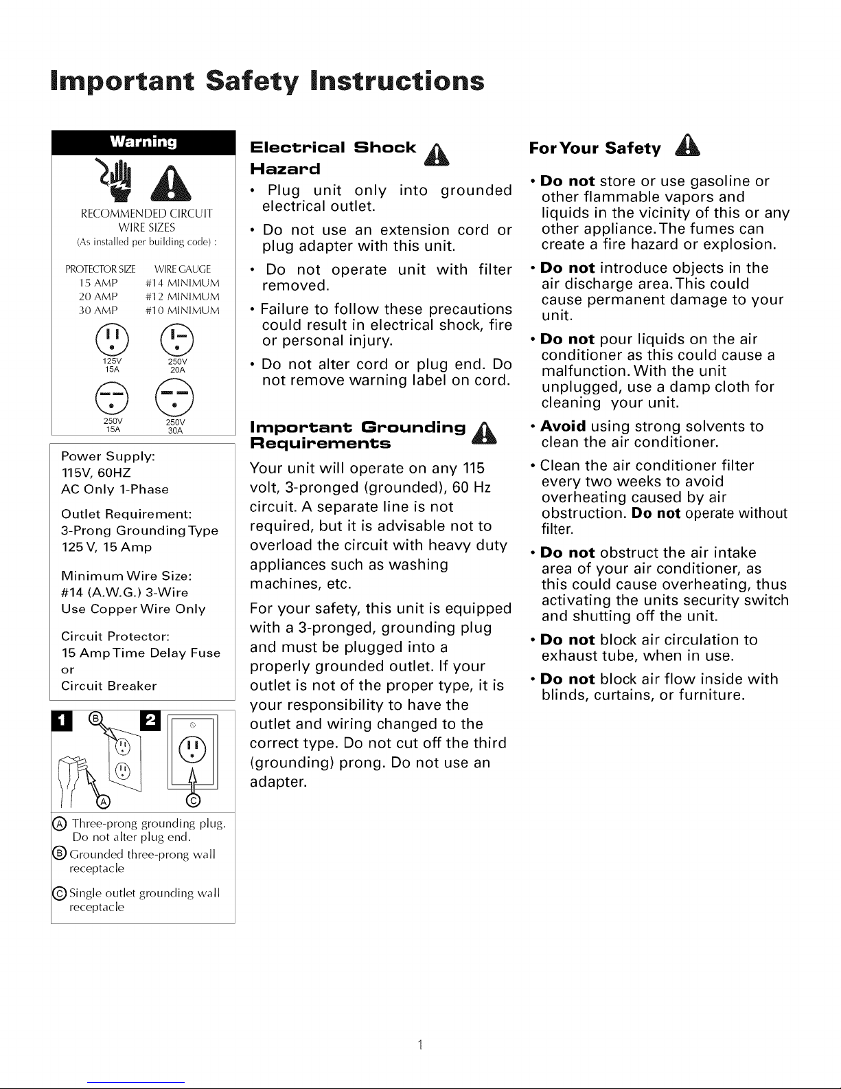
RECOMMENDED CIRCUIT
WIRE SIZES
(As installed per building code) :
PROTECTORSIZE WIRE GAUGE
15AMP #14 MINIMUM
20AMP #12 MINIMUM
30 AMP #10 MINIMUM
©©
125V 250V
15A 20A
©©
250V 250V
15A 30A
Power Supply:
115V, 60HZ
AC Only 1-Phase
Outlet Requirement:
3-Prong Grounding Type
125V, 15Amp
Minimum Wire Size:
#14 (A.W.G.) 3-Wire
Use CopperWire Only
Circuit Protector:
15 AmpTime Delay Fuse
or
Circuit Breaker
M
Electrical Shock
Hazard
• Plug unit only into grounded
electrical outlet.
• Do not use an extension cord or
plug adapter with this unit.
• Do not operate unit with filter
removed.
• Failure to follow these precautions
could result in electrical shock, fire
or personal injury.
• Do not alter cord or plug end. Do
not remove warning label on cord.
Important Grounding _ •
Requirements
Your unit will operate on any 115 •
volt, 3-pronged (grounded), 60 Hz
circuit. A separate line is not
required, but it is advisable not to
overload the circuit with heavy duty •
appliances such as washing
machines, etc.
For your safety, this unit is equipped
with a 3-pronged, grounding plug
and must be plugged into a
properly grounded outlet. If your
outlet is not of the proper type, it is •
your responsibility to have the
outlet and wiring changed to the
correct type. Do not cut off the third
(grounding) prong. Do not use an
adapter.
For Your Safety
Do not store or use gasoline or
other flammable vapors and
liquids in the vicinity of this or any
other appliance.The fumes can
create a fire hazard or explosion.
Do not introduce objects in the
air discharge area.This could
cause permanent damage to your
unit.
Do not pour liquids on the air
conditioner as this could cause a
malfunction. With the unit
unplugged, use a damp cloth for
cleaning your unit.
Avoid using strong solvents to
clean the air conditioner.
Clean the air conditioner filter
every two weeks to avoid
overheating caused by air
obstruction. Be net operate without
filter.
Do not obstruct the air intake
area of your air conditioner, as
this could cause overheating, thus
activating the units security switch
and shutting off the unit.
Do not block air circulation to
exhaust tube, when in use.
De net block air flow inside with
blinds, curtains, or furniture.
C) Three-prong grounding plug.
Do not alter plug end.
(_ Grounded three-prong wall
receptacle
(_) Single outlet grounding wall
receptacle
Page 3
Before Getting Started
BEFORE STARTING YOUR UNIT
• Read the instruction manual before operating the unit
for the first time. It contains important information on
operation, safety, maintenance, service and warranty.
• Keep this instruction manual for future reference.
• Do not start a damaged unit.
•The assembly and connection of the unit must be
carried out according to the instructions. If they are
not followed you run the risk of voiding the warranty.
Important information
1. The power cord is located in the rear of the unit.
2. Do not allow contact between the unit and water.
3. Do not cover the air discharge and air intake louvers
of the unit.
4. Proper venting of the air to the exterior is required
at all times.
The unit hascasters to ease movement. If it is necessaryto
tilt the unit, it must first be emptied of water in the internal
tank using the drain valve at the bottom of the unit. (See
the sectionWhen transporting the unit or Storing the unit
for the season.)
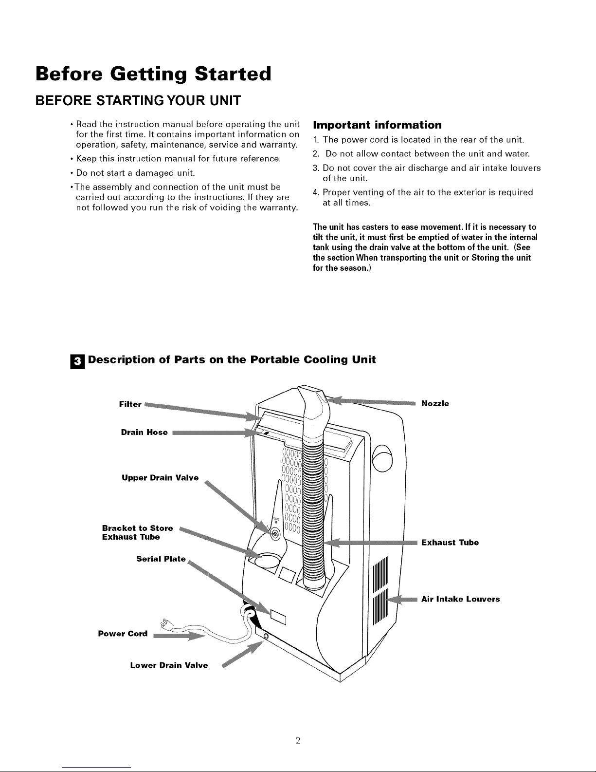
E] Description of Parts on the Portable Cooling Unit
Filter Nozzle
Drain Hose
Upper Drain Valve
Bracket to Store
Exhaust Tube
Serial Plate
Power Cord
Lower Drain Valve
Exhaust Tube
Air Intake Louvers
Page 4
Installation
MOBELE gNSTALLAT ON
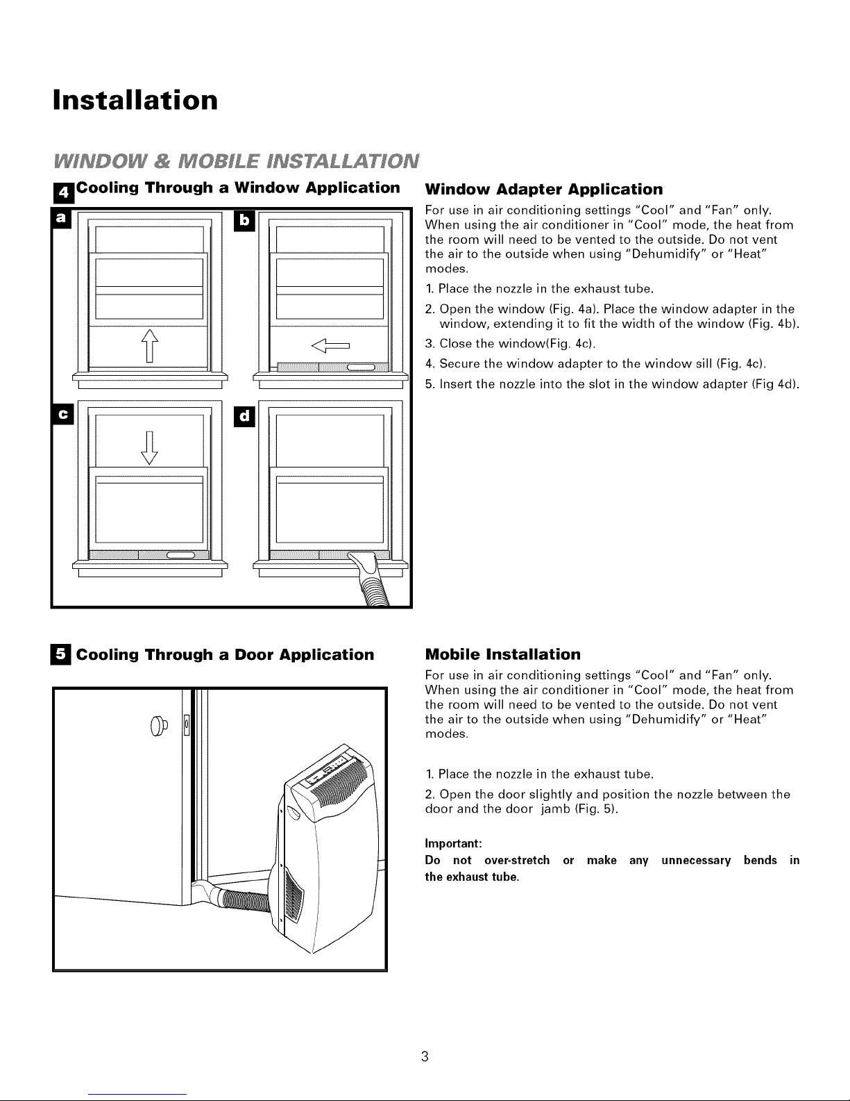
I_Cooling Through a Window Application
u k]
If_ -- I
I I
F
B
I I
13
h
Window Adapter Application
For use in air conditioning settings "Cool" and "Fan" only.
When using the air conditioner in "Cool" mode, the heat from
the room will need to be vented to the outside. Do not vent
the air to the outside when using "Dehumidify" or "Heat"
modes.
1. Place the nozzle in the exhaust tube.
2. Open the window (Fig. 4a). Place the window adapter in the
window, extending it to fit the width of the window (Fig. 4b).
3. Close the window(Fig. 4c).
4. Secure the window adapter to the window sill (Fig. 4c).
5. Insert the nozzle into the slot in the window adapter (Fig 4d).
I_1 Cooling Through a Door Application
Mobile Installation
For use in air conditioning settings "Cool" and "Fan" only.
When using the air conditioner in "Cool" mode, the heat from
the room will need to be vented to the outside. Do not vent
the air to the outside when using "Dehumidify" or "Heat"
modes.
1. Place the nozzle in the exhaust tube.
2. Open the door slightly and position the nozzle between the
door and the door jamb (Fig. 5).
Important:
Do not over-stretch or make any unnecessary bends in
the exhaust tube,
Page 5
Operation
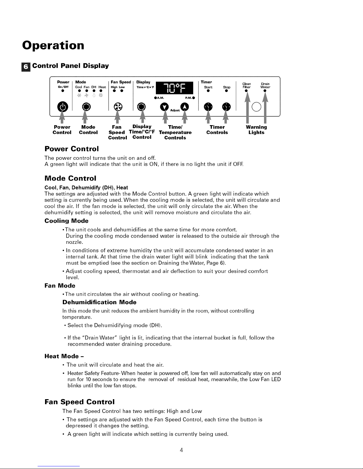
Control Panel Display
Mode
Cool Fan DH Heat
• A.M. P,M._)
Timer
Start Stop
Clean
Filter
i
Power Mode Fan Display Time/ Timer
Control Control Speed Time/°C/°F Temperature Controls
Control Control Controls
Power Control
The power control turns the unit on and off.
A green light will indicate that the unit is ON, if there is no light the unit if OFE
Mode Control
Cool, Fan, Dehumidify (DH), Heat
The settings are adjusted with the Mode Control button. A green light will indicate which
setting is currently being used. When the cooling mode is selected, the unit will circulate and
cool the air. If the fan mode is selected, the unit will only circulate the air. When the
dehumidify setting is selected, the unit will remove moisture and circulate the air.
Cooling Mode
•The unit cools and dehumidifies at the same time for more comfort.
During the cooling mode condensed water is released to the outside air through the
nozzle.
• In conditions of extreme humidity the unit will accumulate condensed water in an
internal tank. At that time the drain water light will blink indicating that the tank
must be emptied (see the section on Draining theWater, Page 6).
• Adjust cooling speed, thermostat and air deflection to suit your desired comfort
level.
Fan Mode
•The unit circulates the air without cooling or heating.
Dehumidification Mode
In this mode the unit reduces the ambient humidity in the room, without controlling
temperature.
• Select the Dehumidifying mode (DH).
Warning
Lights
• If the "Drain Water" light is lit, indicating that the internal bucket is full, follow the
recommended water draining procedure.
Heat Mode -
• The unit will circulate and heat the air.
• Heater Safety Feature-When heater is powered off, low fan will automatically stay on and
run for 10 seconds to ensure the removal of residual heat, meanwhile, the Low Fan LED
blinks until the low fan stops.
Fan Speed Control
The Fan Speed Control has two settings: High and Low
• The settings are adjusted with the Fan Speed Control, each time the button is
depressed it changes the setting.
• A green light will indicate which setting is currently being used.
Page 6
Operation
Display Controls
Time/°C/°F Mode Control: The display control is used to change
the current display setting.
• There are three settings on the display: Temperature in
Fahrenheit,Temperature in Celsius, andTime.
• The display will return from the timer setting to the Fahrenheit
setting after the control has not been depressed for five seconds.
THE TEMPERATURE SETTING ONLY SHOWS THE SET
TEMPERATURE,NOTTHE ROOMTEMPERATURE.
Time/Temperature Controls: These buttons are used to change the
set temperature, the clock, start time, and stop time.
Changing the SetTemperature
Select either Fahrenheit or Celsius on the display by using the
Display Control, then change the set temperature in
increments of 1° using theTime%emperature.
Setting the Clock
Select the time display with the Display Control and change
the clock with the Time/Temperature controls. The time will
increase or decrease in one minute increments with each
depression. If either the up or down buttons is held down, the
time will change continuously until the button is released.The
AM and PM lights will change appropriately with the clock.
Timer Controls
TheTimer Controls can be used to set a time for the air conditioner to
start as well as atime for the air conditioner to stop.
Setting a StartTime
Press the start or stop button. The display will now show the
number of hours until the unit will automatically start.
Use the Time/Temperature controls to adjust the number of
hours before start.The timer will be set after no buttons have
been depressed for five seconds. A light above the start button
will indicate the timer is activated.
Setting a StopTime
While the unit is running, press the stop button. The display
will now show the number of hours until the unit will
automatically stop. Use the Time/Temperature controls to
adjust the number of hours before stop. The timer will be set
after no buttons have been depressed for five seconds. A light
above the start button will indicate the timer is activated.
Shutting theTimer Function OFF
If the Start function is set:
Press the Start button for three seconds. The light will go
off and the start function is now deactivated.
Warning Lights:
These lights will come on when the air conditioner needs attention.
Clean Filter Light
This light indicates that the filter needs to be cleaned. The air
conditioner will continue to run even when the light is on.
However, the filter should be cleaned as soon as possible after
the light comes on. After cleaning the filter, press both
Time/Temperature controls simultaneously to reset the filter
monitor.
Drain Water Light
This light indicates that the internal water bucket needs to be
drained. The unit will not operate until the water has been
drained. See the next page of the owners' manual for
instructions on how to drain the water. The air conditioner
must be set to dehumidify when the water is drained.
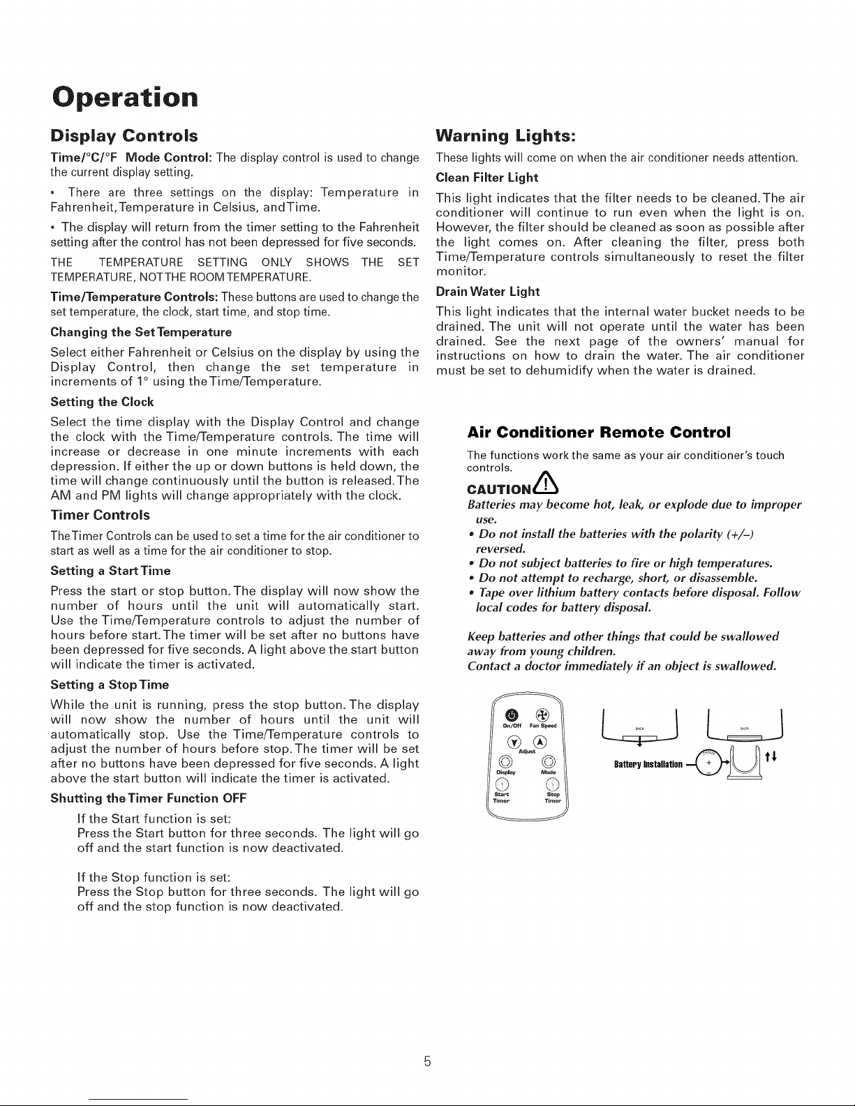
Air Conditioner Remote Control
The functions work the same as your air conditioner's touch
controls.
CAUTION_
Batteries may become hot, leak, or explode due to improper
Use.
, Do not install the batteries with the polarity (+/-)
reversed.
* Do not subject batteries to fire or high temperatures.
* Do not attempt to recharge, short, or disassemble.
o Tape over lithium battery contacts before disposal. Follow
local codes for battery disposal.
Keep batteries and other things that could be swallowed
away from young children.
Contact a doctor immediately if an object is swallowed.
® @
on/off Fan spee(
®®
_iust
© ©
Displav Node
© ©
Sta_ S±Qp
Tiraep Timer
.L4
Batteryinstallation_ t_
If the Stop function is set:
Press the Stop button for three seconds. The light will go
off and the stop function is now deactivated.
Page 7
Maintenance
Upper Drain Valve
CLOSE
@
OPEN
El
(WASH IN WATER EVERY 2
WEEKS)
CLOSE
@
Filter
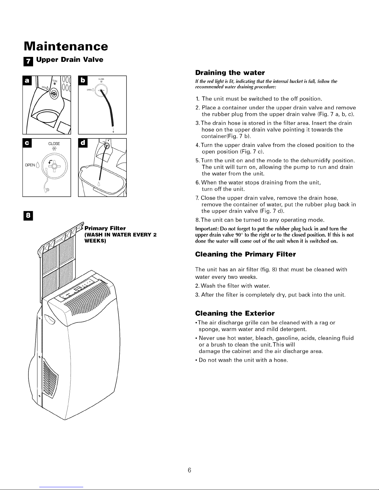
Draining the water
If the red light is lit, indicating that the internal bucket is full, follow the
recommended water draining procedure:
1. The unit must be switched to the off position.
2. Place a container under the upper drain valve and remove
the rubber plug from the upper drain valve (Fig. 7 a, b, c).
3.The drain hose is stored in the filter area. Insert the drain
hose on the upper drain valve pointing it towards the
container(Fig. 7 b).
4.Turn the upper drain valve from the closed position to the
open position (Fig. 7 c).
5.Turn the unit on and the mode to the dehumidify position.
The unit will turn on, allowing the pump to run and drain
the water from the unit.
6.When the water stops draining from the unit,
turn off the unit.
7. Close the upper drain valve, remove the drain hose,
remove the container of water, put the rubber plug back in
the upper drain valve (Fig. 7 d).
8.The unit can be turned to any operating mode.
Important:Do not forgetto putthe rubber plugbackin and turnthe
upperdrainvalve90° to the right or to the closedposition.If this isnot
donethewater will comeout ofthe unit when it isswitchedon.
Cleaning the Primary Filter
The unit has an air filter (fig. 8) that must be cleaned with
water every two weeks.
2. Wash the filter with water.
3. After the filter is completely dry, put back into the unit.
Cleaning the Exterior
•The air discharge grille can be cleaned with a rag or
sponge, warm water and mild detergent.
• Never use hot water, bleach, gasoline, acids, cleaning fluid
or a brush to clean the unit.This will
damage the cabinet and the air discharge area.
• Do not wash the unit with a hose.
Page 8
Maintenance
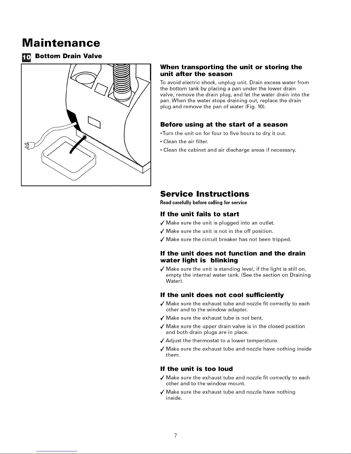
Bottom Drain Valve
When transporting the unit or storing the
unit after the season
To avoid electric shock, unplug unit. Drain excess water from
the bottom tank by placing a pan under the lower drain
valve, remove the drain plug, and let the water drain into the
pan. When the water stops draining out, replace the drain
plug and remove the pan of water (Fig. 10).
Before using at the start of a season
•Turn the unit on for four to five hours to dry it out.
• Clean the air filter.
• Clean the cabinet and air discharge areas if necessary.
Service Instructions
Readcarefully before calling for service
If the unit fails to start
7" Make sure the unit is plugged into an outlet.
7" Make sure the unit is not in the off position.
7" Make sure the circuit breaker has not been tripped.
If the unit does not function and the drain
water light is blinking
7" Make sure the unit is standing level, if the light is still on,
empty the internal water tank. (See the section on Draining
Water).
If the unit does not cool sufficiently
7" Make sure the exhaust tube and nozzle fit correctly to each
other and to the window adapter.
7" Make sure the exhaust tube is not bent.
7" Make sure the upper drain valve is in the closed position
and both drain plugs are in place.
7" Adjust the thermostat to a lower temperature.
7" Make sure the exhaust tube and nozzle have nothing inside
them.
If the unit is too loud
7" Make sure the exhaust tube and nozzle fit correctly to each
other and to the window mount.
7" Make sure the exhaust tube and nozzle have nothing
inside.
Page 9

Warranty
For Models Installed
in North America - if Service
or Parts are Required
First, make the recommended checks. If it appears that
service or parts are still required, see your room air
conditioner warranty "How to Obtain Warranty Service
or Parts':
For Models |nstalled
Outside North America
For room air conditioners purchased for use outside
North America, the manufacturer does not extend any
warranty either expressed or implied. Consult your local
dealer for any warranty terms extended by the importer
in your country.
Room Air Conditioner Warranty
(Within the 48 contiguous United States, state of Hawaii,
the District of Columbia, Puerto Rico and Canada)
Full (Five Year} Parts and Labor Warranty
During the five years after the date of original purchase,
Fedders Appliances will, through its authorized servicers
and free of charge to the owner or any subsequent user,
repair or replace any parts which are defective in
material or workmanship due to normal use. Ready
access to the air conditioner is the responsibility of the
owner.
Note: In the event of any required parts replacement
within the period of this warranty, Fedders Appliances
replacement parts shall be used and will be warranted
only for the period remaining on the original warranty.
Exceptions
The above warranty does not cover failure to function
caused by damage to the unit while in your possession
(other than damage caused by defect or malfunction), or
by its improper installation, or by unreasonable use of
the unit, including without limitation, failure to provide
reasonable and necessary maintenance or to follow the
written Installation and Operating Instructions. If the unit
is put to commercial, business, rental, or other use or
application other than for consumer use, we make no
warranties, express or implied, including but not limited
to, any implied warranty of merchantability or fitness for
particular use or purpose.
Some states do not allow limitations on how long an
implied warranty lasts or do not allow the exclusion or
limitation of incidental or consequential damages, so
the above limitations or exclusions may not apply to
you.This warranty gives you specific legal rights, and
you may also have other rights which may vary from
state to state.
No warranties are made for units sold outside of the above
stated areas. Your distributor or final seller may provide a
warranty on units sold outside of these areas.
How to Obtain
Warranty Service or Parts
Service for your room air conditioner will be provided
by CareCo, a division of the manufacturer with
authorized independent CareCo servicers nationwide.
Note: Before calling for service, carefully read the
Installation and Operating Instructions booklet. Then if
you need service:
1. Call a CareCo authorized servicer and advise them of
model number, serial number, date of purchase and
nature of complaint. Service will be provided during
normal working hours. Contact your dealer for the
name of an authorized servicer if unknown to you.
2. If your dealer is unable to give you the name of a
servicer or if you need other assistance, call the
following toll-free number for the name of an
authorized servicer or authorized parts distributor:
1=8664VlAYTAG 1
or you may write:
CareCo, Service Department
415 W Wabash Ave., RO. Box 200
Effingham, IL 62401
Proof of Purchase Date
It is the responsibility of the consumer to establish the
original purchase date for warranty purposes. We
recommend that a bill of sale, cancelled check, or some
other appropriate payment record be kept for that
purpose.
THE REMEDIES PROVIDED FOR INTHE ABOVE EXPRESS
WARRANTY ARETHE SOLE AND EXCLUSIVE REMEDIES
THEREFOR, NO OTHER EXPRESS WARRANTIES ARE
MADE. ALL IMPLIED WARRANTIES, INCLUDING BUT
NOT LIMITEDTO ANY IMPLIED WARRANTY OF
MERCHANTABILITY OR FITNESS FOR A PARTICULAR
USE OR PURPOSE, ARE LIMITED IN DURATIONTO FIVE
YEARS FROMTHE DATE OF ORIGINAL PURCHASE. IN
NO EVENT SHALL Fedders Appliances BE LIABLE FOR
INDIRECT, INCIDENTAL, OR CONSEQUENTIAL
DAMAGES, EVEN IF ADVISED IN ADVANCE OFTHE
POSSIBILITY OF SUCH DAMAGES. NO WARRANTIES,
EXPRESS OR IMPLIED, ARE MADETO ANY BUYER
UPON RESALE.
Page 10

TAMANOS RECOMENDADOS
DE LOS CONDUCTORES DEL
CIRCUITO
(Instaladosseg[inel c6digo de
construcci6n) :
CAPACIDADDE CALIBREDELOS
LOSFUSIBLES CQNDUCTORES
15AMP #14 COMO MINIMO
20AMP #12 COMO MINIMO
30AMP #10 COMO MINIMO
©©
125V 250V
15A 20A
©©
250V 250V
15A 30A
C) Enchufe de tres clavijas con
puesta a tierra. No
Modifique.
C) Tomacorriente para enchufe
de tres clavijas conpuesta a
tierra.
(_) Tomacorriente mural
sencillo con puesta a tierra.
Riesgo de Choque EI6ctrico
• Enchufe el aparato solamente en un
tomacorriente el6ctrico puesto a tierra.
• Con este aparato no use un cord6n de
extensi6n ni un adaptador de enchufe.
• No haga funcionar el acondicionador de
aire sin el panel delantero.
• El incumplimiento de estas precauciones
pueden causar un choque el6ctrico, incendio o
lesi6n personal.
• No modifique el cord6n ni el enchufe del
extremo.
Requisitos importantes
A
para la conexi6n a tierra
Su unidad funcionara en cualquier circuito
de 115 voltios, de 3 patillas (con conexion a
tierra) y 60 Hz. No se requiere linea
separada, pero es aconsejable no
sobrecargar el circuito con artefactos que
usan mucha corriente como maquinas de
lavar ropa, etc. Para su seguridad, esta
unidad esta equipada con un enchufe de 3
patillas de conexion a tierra y debe
enchufarse en un tomacorriente con la
debida conexion a tierra (Figuras 1 y 2).
Si su tomacorriente no es del tipo
adecuado, usted tiene la responsabilidad de
hacer que se cambien tanto el
tomacorriente como los alambres al tipo
adecuado.
No corte la tercera patilla de conexion a
tierra. No use un adaptador.
Para su seguridad
• No guarde ni use gasolina u otros vapores y
Ifquidos inflamables en 14::lindad de este
A
o cualquier otro artefacto. Los vapores
emitidos pueden crear un riesgo de
incendio o explosi6n.
• No introduzca objetos en el a'rea de
descarga del aire. Esto puede causar datio
irreparable a su acondicionador de aire.
• No vierta Ifquidos de limpieza en el
acondicionador de aire pues esto puede
causarun malfuncionamiento. Useun
patio ht_medo para limpiarlo.
• Evite usar solventes fuertes para limpiar el
acondicionador de aire.
Limpie el filtro del acondicionador de aire
cada dos semanas para evitar
sobrecalentamiento causado por
obstrucci6n del aire.
• No obstruya el a'rea de entrada del aire de
su acondicionador, pues esto puede causar
sobrecalentamiento, Io cual activara" el
interruptor de seguridad y apagara" el
aparato.
• Do not block air circulation to exhaust tube,
when in use
• No obstruya el flujo del aire hacia el
interior con persianas, cortinas o muebles
Suministro
de corriente:
Tomacorriente
clue se requiere: De 3 patillas,
Tamaffo mfnimo
rlel alambre: No. 14 (A.W.G.) de 3 alambres
Protector del
drcuito: Fusible con retardo de
llSE 60HZ
Cordente alterna monof#sica
solamente
tipo conexi6n a tierra
125V,, 15Amp
Use solamente
alambre de cobre
tiempo o interruptor de
circuito de 15 Amp
Page 11

Antes de empezar
ANTES DE ENCENDER SU UNIDAD
• Antes de usar la unidad por la primera vez, lea el manual
de instrucciones que contiene informaci6n importante
sobre su operaci6n, seguridad, mantenimiento, servicio y
garantfa.
• Guarde este manual de instrucciones para consultarlo en
el futuro.
• No encienda una unidad que est6 dahada.
• El ensamblado y la conexi6n de la unidad debe Ilevarse a
cabo de acuerdo alas instrucciones. Si no se siguen,
usted toma el riesgo de invalidar la garantfa.
_] Descripci6n de las partes
de la unidad de enfriamiento portatil
Filtro
Informacibn importante
1. El cord6n de electricidad esta" situado en la parte posterior
de la unidad.
2. No deje que la unidad est6 en contacto con el agua.
3. No cubra las rejillas de descarga y de toma
de aire de la unidad.
4. En todo momento se necesita una salida adecuada del
aire al exterior.
La unidad tiene ruedas para facilitar el movimiento.
Si es necesario inclinarla, se debe primero vaciar el agua del
tanque interno, usando la valvula de drenaje en la parte
inferior.Vea la seccion si se transporta o almacena la unidad
durante la estacion.
Boquilla
Manguera
de drenaje
V&lvula de
drenaje superior
Bracket to Store
Exhaust Tube
Placa con el
n_mero de
Cord6n de
electricidad
V&lvula de drenaje
inferior
Tube
Rejillas de toma
de aire
10
Page 12

Instalaci6n
Ve_a_a Y Poct_dE Y_s_Macfd_
I_Colocacibn del adaptador de ventana
u NI
If- -- I
I I
F
B
I I
D
h
Colocacibn del adaptador de ventana
Para uso en los ajustes "Cool" (Frfo) y "Fan" (Ventilador)
solamente. Cuando use el acondicionador de aire en el modo
"Cool" el aire caliente de la habitacion debe ser ventilado
hacia el exterior. No ventile el aire hacia el exterior cuando use
los modos "Dehumidify" (Deshumidificacion) o "Heat" (Calor).
1. Coloque la boquilla en el tubo de escape.
2. Abra la ventana (Fig.4a) y coloque el adaptador,
extendiendolo para que se acomode a la anchura de la
ventana; cierre la ventana (Fig.4h).
a. Asegure el adaptador para la ventana en el alfeizar de la
ventana (Fig.4c).
4. Inserte la boquilla en la ranura del adaptador para ventana
(Fig.4d).
I_1 Aire acondicionado poniendo la
unidad en una puerta
Instalacibn port&til
Para uso en los ajustes "Cool" (Frio) y "Fan" (Ventilador)
solamente. Cuando use el acondicionador de aire en el modo
"Cool" el aire caliente de la habitacion debe ser ventilado
hacia el exterior. No ventile el aire hacia el exterior cuando use
los modos "Dehumidify" (Deshumidificacion) o "Heat" (Calor).
1. Coloque la boquilla en el tubo de escape.
2. Abra la puerta un poco y coloque la boquilla entre la
puerta y la jamba (Fig. 5).
Importante: No extienda el tubo de escape ni Io doble sin
necesidad.
11
Page 13

Funcionamiento
J_ Panel de Control
Mode
Cool Fan DH Heat
• A.M. P.M.S)
Timer Clean Drain
Start Stop Filter Water
i
Control de Control Control de la Display Controles de Controles del Luces de
Alimontaci6n do Modo Velocidad TimoI°CI°F Hora/ Roloj Advortoncia
Control de Alimentacibn
Este bot6n pone en marcha y apaga el acondicionador de aire.
Control de modo
Modo 'Cool' (Fri6), Modo 'Fan' (Ventilador), Modo 'DH' (Deshumidificador), y Modo 'Heat' (Calor) [solamente los modelos con calor].
Las posiciones se ajustan con el bot6n de control de modo. La luz verde indica que el modo se encuentra actualmente en uso. Cuando
se selecciona el modo 'Cool' (enfriamiento), la unidad hara" circular el aire y Io enfriara'. Si se selecciona modo 'Fan' (ventilaci6n) la
unidad s61o hara" circular el aire. Cuando se selecciona la funci6n de deshumidificaci6n, la unidad eliminara" la humedad y hara" circular
el aire. Cuando se selecciona el modo 'Heat' (calor), la unidad calentara" y hara" circular el aire.
Modo 'Cool' (Fri6)
• Para mayor confort, la unidad enfrfa y deshumedece al mismo tiempo. Durante el modo de enfriamiento, el agua condensada
pasa al exterior por medio de la boquilla.
• En condiciones de humedad extrema la unidad acumulara" el agua condensada en un tanque interno. En este caso la luz roja se
encendera" para indicar que se debe vaciar el tanque. Vea la secci6n sobre Drenaje del agua.
• Ajuste la velocidad de enfriamiento, el termostato y la deflexi6n de aire al nivel de confort deseada.
Modo 'Fan' (Ventilador)
• El acondicionador de aire solamente hara" circular el aire.
Modo 'DH' (Deshumidificador)
En el modo de deshumidificador, la unidad reduce la humedad del ambiente en la habitaci6n.
1. Compruebe que la va'lvula de drenaje superior est6 en la posici6n de cierre y que el tap6n de caucho est6 en su lugar (Fig. 7 d).
2. Escoja el modo de deshumedecer (Fig. 6).
3. Si la luz roja que indica que el balde interno esta" Ileno se enciende, siga el procedimiento que se recomienda para drenaje.
del Control Tomporatura
Ventilador
Modo 'Heat' (Calor) [solamente los modelos con resistencia electrica] -
• El acondicionador de aire circula y calienta el aire.
• Caracterfstica de Seguridad del Calentador - Cuando el calentador esta" apagado, el ventilador de baja velocidad se activara" y
funcionara" durante 10 segundos para asegurar la eliminaci6n de alg_n calor residual, a la vez que el diodo LED 'Low Fan'
(ventilador de baja velocidad) destella hasta que se detenga el ventilador de baja velocidad.
Control de la Velocidad del Ventilador 'Fan Speed' • Alta y Baja
El ajuste de la velocidad del ventilador se cambia cada vez que se oprime el bot6n de control de velocidad del ventilador.
• Una luz verde indicara" el ajuste que se ha seleccionado.
12
Page 14

Funcionamiento
Controles de[ [ndicador Visual
Control de los Modos 'Time/°C/°F ' (Tiempo/°C/°F): El control
del indicador visual se usa para cambiar el ajuste actual.
. Hay tres ajustes en el indicador visual:Temperatura en
grados Fahrenheit, Temperatura en grados Celsius y el Reloj
. El indicador visual volver_ del ajuste de la hora al ajuste
Fahrenheit si el control no ha sido oprimido durante cinco
segundos.
. La temperatura en el indicador visual es la temperatura
implfcita. NO es la temperatura real de la habitaci6n.
Controies del Tiempo/Temperatura:
Estas teclas se usan para cambiar el ajuste de la
temperatura, para cambiar la hora, para cambiar el tiempo
de puesta en marcha y el tiempo de parada.
Cambio del Ajuste de [aTemperatura
Seleccione ya sea grados Fahrenheit o Celsius en el indicador
visual usando el control del indicador visual y luego cambie
el ajuste de la temperatura en incrementos de 1° usando la
tecla 'Time!Temperature' (Tiempo/Temperatura).
Programaci6n del Reloj
Seleccione la visualizaci6n de la hora con el control del
indicador visual y cambie el reloj con los controles
'Time/Temperature'. La hora aumentar_ o disminuir_ en
incrementos de un minuto cada vez que oprime la tecla. Si se
mantiene oprimido ya sea el bot6n flechado hacia arriba o
hacia abajo, la hora cambiar_ continuamente hasta que se
deje de oprimir la tecla. Las luces AM y PM cambiar_n de
acuerdo con el cambio de la hora.
Controles de[ Temporizador
Los controles del temporizador ('Timer') pueden usarse para
programar la hora en que se desea que el acondicionador de
aire se ponga en marcha asi como tambien la hora en que se
desea que el acondicionador de aire se apague.
Programaci6n de un tiempo de Puesta en Marcha
Oprima la tecla 'start' (puesta en marcha) o 'stop' (parada). El
indicador visual mostrara entonces el nQmero de horas que
falta para la puesta en marcha autom_tica del
acondicionador.
Use los controles del tiempo y de la temperatura para
programar el nQmero de horas antes de la puesta en marcha.
El temporizador se programar_ si no se oprime ninguna tecla
durante cinco segundos. Una luz indicadora situada arriba de
la tecla 'Start' se ilumina indicando que el temporizador est_
activado.
Programaci6n de un Tiempo de Parada
Cuando el acondicionador est_ en funcionamiento, oprima la
tecla 'Stop' (parada). El indicador visual mostrar_ el nQmero
de horas que faltan para que el acondicionador se detenga
autom_ticamente. Use los controles del tiempo y de la
temperatura para programar el nQmero de horas antes de la
parada. El temporizador se programara si no se oprime
ninguna tecla durante cinco segundos. Una luz indicadora
situada arriba de la tecla 'Start' se ilumina indicando que el
temporizador est_ activado.
CANCELACION de la funci6n de[ temporizador
Si est_ programada la puesta en marcha:
Oprima la tecla 'Start' durante tres segundos. La luz se
apagar_ y la funci6n de puesta en marcha queda
desactivada.
Si esta programada la parada:
Oprima la tecla 'Stop' durante tres segundos. La luz se
apagar_ y la funci6n de parada queda desactivada.
Luces de Advertencia: Estas luces se iluminar_n cuando el
acondicionador de aire necesite atenci6n especial.
Luz de Limpieza de[ Filtro
Esta luz indica que el filtro debe ser limpiado. El
acondicionador de aire continuar_ funcionando aun cuando
la luz este encendida. Sin embargo, el filtro debe ser
limpiado tan pronto como sea posible despues que la luz se
ilumina. Despues de limpiar el filtro, oprima
simult_neamente las teclas 'Time/Temperature'
(Tiempo/Temperatura) para reactivar el monitor del filtro.
Luz de Vaeiado del Agua
Esta luz indica que el dep6sito interno del agua necesita ser
vaciado. El acondicionador no funcionar_ hasta que no haya
sido vaciado. Vea la p_gina siguiente del manual del usuario
para obtener las instrucciones sobre como vaciar el dep6sito.
El acondicionador de aire debe estar ajustado para
deshumidificaci6n cuando el agua est_ siendo extraida.
Control Remoto del Acondicionador de Aire
Las funciones son id6nticas a ]as de los contro]es sensibles al tacto de su
acondicionador de aire,
ATENC|ON
Las pilas se pueden calentart tenet escape o explotar debide al
use incorrecto.
* No instale/as pilas con la polaridad (+/I-) inversa.
* No exponga/as pilas al fuego o a temperaturas altas.
* No intente recargart cortocircuitar o desarmar/as pilas.
Mantenga fuera del alcance de los nifios pequefios /aspilas y
etros artfculos que puedan set tragados. P6ngase
inmediatamente en contacto con un m_dice si un nifio
pequefio se traga un objeto.
® @
On/O# Fan Sp_c
®®
_Jlius_
© ©
D_pla v Mode
© ©
Sta_ S_p
Time_" Tiraer
Batteryinstallation_ 1_'
13
Page 15

Mantenimiento
El
OPEN
El
CLOSE
Filtro Principal de Aire
(limpiar con agua cada
dos semanas)
Drenaje del agua
Si se enciende la luz roja que indica que el balde interno est6
Ileno, siga el procedimiento que se recomienda para el drenaje:
1. Debe apagarse la unidad.
2. Coloque el recipiente bajo la va'lvula de drenaje superior y
saque el tap6n de caucho de dicha va'lvula (Fig. 7 a, b, c).
3. Inserte la manguera de desagLie en la va'lvula de drenaje
superior apuntando hacia el recipiente.
4. Mueva la va'lvula de drenaje superior de la posici6n de cerrado
a abierto (Fig. 7 b).
5. Encienda la unidad, ponga el interruptor en posici6n modo de
deshumidificaci6n, y la unidad se encendera', Io que permite que
funcione la bombay drene el agua (Fig. 6).
6. Apague la unidad cuando ya no salga agua.
7. Cierre la va'lvula de drenaje superior, saque la manguera de
drenaje, retire el recipiente de agua y vuelva a poner el tap6n de
caucho en la va'lvula de drenaje superior (Fig. 7 d).
8. Ahora la unidad puede ponerse en el modo de operaci6n
que desee.
Importante: Cuando cambie el modo de operaci6n nuevamente a
enfriamiento, no se olvide de volver a poner el tap6n y de girar la
va'lvula de drenaje superior 90 ° a la derecha o a la posici6n de
cierre. Si no realiza esta operaci6n, saldra" agua de la unidad al
encenderla.
Limpieza del filtro
El acondicionador de aire tiene un filtro de aire que debe
ser limpiado con agua cada dos semanas. Lave el filtro con
agua. Despu_s de que el filtro este completamente seco,
coloquelos de vuelta en el acondicionador de aire.
Limpieza el exterior
• La rejilla de salida del aire puede limpiarse con un trapo o
una esponja, agua tibia y un detergente suave.
• Nunca use agua caliente, lejfa, gasolina, a'cidos, Ifquidos de
limpieza ni cepillos para limpiar la unidad. El hacerlo daffara"
el gabinete y la zona de descarga del aire.
• No lave la unidad con una manguera.
14
Page 16

Mantenimiento
Valvula de drenaje inferior
Instrucciones de Servicio
L6alas cuidadosamente antes de solicitar el servicio.
Si se transporta la unidad o se guarda
despu_s de la estacibn
To avoid electric shock, unplug unit.
Drene el exceso de agua del tanque inferior colocando una
bandeja debajo del orificio de drenaje inferior. Retire el tap6n de
goma y deje que el agua drene hacia la bandeja. Cuando deje de
salir agua, vuelva a colocar el tap6n de drenaje inferior y retire la
bandeja con agua (Fig. 10).
Antes de usar la unidad al comienzo de la
estacibn
• Encienda la unidad durante cuatro o cinco horas
para que se seque.
• Limpie el filtro de aire.
• Limpie el gabinete y las zonas de descarga
del aire si es necesario.
Si la unidad no enciende
• Compruebe que la unidad est6 enchufada a un tomacorriente.
• Compruebe que la unidad no est6 en la posici6n de apagado.
• Compruebe que el interruptor del circuito no haya saltado.
Si la unidad no funciona y la luz roja esta encendida
• Verifique que la unidad est6 nivelada; si la luz sigue encendida, vacfe el
tanque interno de agua (vea la secci6n sobre Drenaje del agua).
Si la unidad no enfria Io suficiente
• Compruebe que el tubo de evacuaci6n de aire y el difusor est6n
conectados entre sf y tambi6n al adaptador de ventana.
• Compruebe que el tubo de evacuaci6n de aire no esta doblado.
• Compruebe que las va'lvulas de drenaje estan en su sitio yen
posici6n de cerrado.
• Ponga el termostato a una temperatura ma's baja.
• Compruebe que el tubo de evacuaci6n de aire y el difusor
no tengan nada dentro.
Si la unidad hace demasiado ruido
• Compruebe que el tubo de evacuaci6n de aire y el difusor est6n conectados
entre sf y tambi6n al adaptador para la ventana.
• Compruebe que el tubo de evacuaci6n de aire y el difusor no
tengan nada dentro.
15
Page 17

Garantia ooooooooooooooooooooo
0000000000000000000000000000000
Para modelos instalados en
Norteam6rica - En caso de necesidad
de servicio o piezas
Haga primer() las verificaciones recomendadas. En caso
de necesitarse servicio o piezas, consulte en la garantia de
su acondicionador de aire en la secci6n "C6mo obtener
servicio o piezas de garantia'.
Para modelos instalados
fuera de Norteam_rica
Para aires acondicionados comprados para uso fuera de
Norteam_rica el fabricante no otorgar_ ninguna garantia
implicita o explicita. Consulte a su distribuidor
autorizado sobre las condiciones de la garantia extendida
pot el importador de los equipos de su pais.
Garantia del acondicionador de aire
(Dentro de los 48 estaclos contiguos de los Estaclos
Unidos, estaclo de Hawai, Distrito de Columbia, Puerto
Rico y Canacla)
Garantia para todas las piezas (cinco a_os)
y mano de obra
A partir de la fecha de compra y durante un periodo de
cinco aflos, Fedders Appliances, mediante sus estaciones
de servicio autorizadas, repararfi o reemplazarfi sin costo
alguno para el propietario o usuario, cualquier pieza que
presente dafios de material o mano de obra derivados del
uso normal del producto. Es responsabilidad del
propietario facilitar el acceso al acondicionador de aire
para realizar los servicios de reparaci6n.
Nota: En caso de que se requiera reemplazar una pieza
mientras la garantia esta vigente, se utilizaran los
repuestos de Fedders Appliances los cuales continuaran
en vignecia solamente durante el resto del periodo de
garantia de la unidad.
Excepciones
La garantia antes indicada no cubre las fallas de
funcionamiento causadas por daflos que sufra la unidad
mientras _sta est_ en posesiOn del usuario (excluyendo los
daflos causados por defecto o funcionamiento
defectuoso), o por la instalacidn incorrecta, o la utilizaciOn
indebida de la unidad, incluyendo pero sin limitarse a
ello, la negligencia en proporcionar el mantenimiento
necesario y adecuado o en seguir las "instrucciones de
InstalaciOn y Uso" indicadas por escrito. En caso de
utilizarse la unidad para fines comerciales, de negocios, de
arriendo u otro uso o aplicaciOn que no sea el uso del
consumidor, no otorgamos garantia explicita ni implicita,
incluyendo, pero sin limitarse a, toda garantia implicita de
negociabilidad o idoneidad para un uso o finalidad
particular.
LAS SOLUCIONES EXPUESTAS EN LA (;ARANTIA
ANTERIOR SON EXCLUSIVA8. SE RECHAZA CUALQUIER
OTRA GARANTIA YA SEA EXPRESA 0 IMPLICITA,
INCLUYENDO, PERO SIN LIMITARSE A ELLO, TODAS LAS
GARANTIAS DE COMERCIABILIDAD 0 IDONEIDAD PARA
UN FIN EN PARTICULAR DURANTE CINCO ANOS A
PARTIR DE LA FECHA DE COMPRA. BAJO NINGUNA
CIRCUNSTANCIA Fedders Al_,liances SE HARA
RESPONSABLE POR NINGUN DAN() DIRECT(), INDIRECT()
0 CONSECUENCIAL, SIN IMPORTAR LA CAUSA DE LA
ACCION, AUN CUANDO Feddet_s Aplfliances HAYA SIDO
ADVERTIDO CON ANTERIORIDAD DE LA POSIBILIDAD
DE DICHOS DANOS. NO SE OFRECE NINGUNA (;ARANTIA
EXPRESA 0 IMPLICITA A COMPRADORES DESPUES DE LA
REVENTA.
Algunos estados no permiten limitar el tiempo de
duracidn de una garantia implicita ni permiten excluir ni
limitar los daflos incidentales o emergentes, de modo que
las limitaciones o exclusiones antes indicadas podrian no
aplicarse en su caso. Esta garantia le otorga derechos
legales especificos. Usted podria tener tambi_n otros
derechos que pueden variar de estado a estado.
No se ofrecen garantias para las unidades vendidas fuera
de las _reas antes indicadas. Su distribuidor o vendedor
final podria proporcionar una garantia para las unidades
vendidas fuera de estas _reas.
C6mo obtener servicio
o piezas de garantia
E1servicio para su acondicionador de aire ser_ provisto por
CareCo, una divisi6n del fabricante con estaciones de
servicio independientes CareCo autorizadas en todo el
pais.
Nora: Antes de solicitar servicio, lea cuidadosamente el
folleto de "lnstrucciones de Instalacion y Uso" Luego, si
necesita servicio:
1. Llame a un taller de servicio autorizado CareCo y
suministreles el nfimero de modelo, nfimero de serie, la
fecha de compra y la naturaleza del problema. E1 servicio
se prestar_ durante horas normales de trabajo.
Comuniquese con su distribuidor para obtener
recomendaciones sobre una estaci6nde servicio
autorizada.
2. Si su distribuidor no puede proporcionarle el nombre
de un taller de servicio o si necesita otro tipo de
asistencia, llame al siguiente nfimero gratis para
obtener el nombre de un taller de servicio autorizado o
distribuidor de piezas autorizado:
1-866-MAYTAG 1
o escriba al:
Departamente de Servicio de CareCo
415 W. Wabash Ave., RO. Box 200
Effingham, IL 62401 EE. UU.
Prueba de la fecha de compra
E1 establecimiento de la fecha de compra original para
efectos de la garantia es responsabilidad del consumidor.
Recomendamos mantener la factura de compra, el cheque
cancelado o algOn otro registro de pago apropiado para
dicho efecto.
16
Page 18

i = = -
CALIBRERECOMMAND[_DES
CONDUCTEURS
(selonlecodedub_timent):
CAPACITI_ CALIBREDES
DUFUSIBLE CONDUCTEURS
15A NO14ouplus gros
20A NO12ouplusgros
30A No10ouplus gros
©©
125V 250V
15A 20A
©©
250V 250V
15A 30A
(_ Fiche de branchement _ trois
broches (liaison _ laterre).
Ne pas modifier la fiche de
branchement.
I_) Prises de courant murales
trois alv6oles(liaison _ la
terre).
Risque de choc _lectrique _
• Brancher I'appareil uniquement sur une
prise de courant electrique reliee a la terre.
• Ne pas utiliser avec cet appareil un c_ble
de rallonge ou un adaptateur de fiche.
• Ne pas faire fonctionner cet appareil
Iorsque le filtre a air est enleve.
• Le non-respect de ces precautions peut
entraTner choc electrique, incendie ou
blessures.
• Ne pas modifier le cordon d'alimentation
ou la fiche de branchement. N'enlever
aucune etiquette d'avertissement fixee sur
le cordon d'alimentation.
Liaison & la terre- Exigences Zi,
importantes
• Pour la protection des utilisateurs contre
les risques de choc electrique, le climatiseur
comporte un cordon d'alimentation muni
d'une fiche de branchement a trois broches
(liaison a la terre) qu'on dolt brancher sur
une prise de courant murale a trois alveoles
convenablement reliee a la terre. Pour un
modele dont la demande de courant est de
7,5 A ou moins, utiliser une prise de courant
murale reliee a la terre de m6me
configuration que la fiche de branchement.
• Pour un modele dont la demande de
courant est superieure a 7,5A, utiliser une
prise de courant simple avec liaison a la
terre, de m6me configuration que la fiche de
branchement.
Mesures de s_curit_ additionnelles
• Ne jamais remiser ou utiliser d'essence ou
autre produit inflammable liquide ou gazeux
au voisinage des appareils ou de tout autre
appareil menager. Les vapeurs emises
pourraient entraTner un risque d'incendie ou
d'explosion.
• N'introduire aucun objet dans la zone de
decharge de Pair; ceci pourrait provoquer
une deterioration non reparable de
I'appareil.
• Ne verser aucun liquide sur le climatiseur;
ceci pourrait entraTner une anomalie de
fonctionnement. Pour le nettoyage de
I'appareil, utiliser un chiffon humide.
• Lors du nettoyage du climatiseur, eviter
d'employer un solvant energique.
• Pour eviter une obstruction et un
echauffement excessif, nettoyer le filtre du
climatiseur a intervalles de deux semaines.
• Veiller a ne pas obstruer les entrees d'air
du climatiseur; ceci provoquerait un
echauffement excessif et le declenchement
des dispositifs de securite qui provoquent
I'arr6t de I'appareil.
• Ne pas bloquer la circulation de I'air vers
les claires-voies exterieures de la caisse.
• Ne pas bloquer la circulation de I'air au
voisinage de I'appareil, a I'interieur (stores,
rideaux, meubles), ou a I'exterieur
(arbustes, enceintes ou autre b_timent).
(_ Prise de courant murale
simple avec liaison _ la terre.
Alimentation
dectrique:
monophas_
Prise
d'alimentation: Prise avec mise _ la terre
Calibre de fil
minimum: #14 A.W.G.
Protection
du circuit:
115V, 6OHZ
c. a. seulement
3 trous 125V, 15A
3 conducteurs,
fil de cuivre seulement
Fusible temporis#
ou disjoncteur 15A
17
Page 19

Pr6paratifs
Avant de mettre I'appareil en marche
• Lire le manuel d'instructions avant de faire
fonctionner I'appareil pour la premiere fois.
Le manuel contient des renseignements sur I'utilisation et
I'entretien de I'appareil, la garantie ainsi que des consignes
de securite.
• Conserver ce document pour reference ulterieure.
• I_viter de mettre I'appareil en marche s'il est endommag&
• £assemblage et le branchement de cet appareil doivent
6tre effectu6s conformement aux instructions de la
garantie.
Renseignements importants
1. Le cordon d'alimentation est situ6 a I'arriere de
I'appareil.
2. I_viter le contact de I'appareil avec I'eau.
3. Ne pas couvrir I'entree ni la sortie d'air de I'appareil.
4. £appareil dolt 6tre adequatement ventile vers I'exterieur
en permanence.
Apr#s avoir arr#t# le syst#me, attendre au moins 3 minutes avant de le
remettre en marche.
L'appareil est pourvu de roulettes destinies _ faciliter son transport. S'il
est n#cessaire d'incliner I'appareil, le r#servoir de celui-ci dolt d'abord
#tre vid# (utiliser le robinet de vidange situ# au bas de I'appareil).
R6f6rez-vous _ la section Awmt de transporter I'appareil ou De le i_mger
pour la saison.
I_1 Description des pi6ces du climatiseur portatif
Filtre Buse
Tuyau de vidange
Robinet de vidange
sup6rieur
Plaque signal6tique
Cordon
d'alimentation
Tube d'6chappement
Bouche d'entr6e
d'air
Robinet de vidange
inf6rieur
18
Page 20

Pr6paratifs
FENETRE & MOBILE INSTALLATION
I_lClimatisation Iorsque I'appareil est
mont_ dans une porte
A i
I/- -- I
I I
B
I
D
Window Adapter Application
Pour utilisation avec les r6glages _<Cool_ (Froid) et _<Fam_
(Ventilateur) seulement. Lors de I'utilisation du climatiseur en mode
<<Cool>>,la chaleur de la piece doit 6tre 6vacu6e vers I'ext6rieur. L'air
ne doit pas 6tre 6vacu6 vers I'ext6rieur Iors de I'utilisation des modes
<<Dehumidify>> (D6shumidication)ou <<Heat>>(Chauffage).
Installation dans une fen_tre
1. Placer la buse dans le tube d'echappement (Fig. 4a).
2. Ouvrir la fen&tre et y placer I'adapteur pour fen&tre. [_tirer
I'adaptateur sur la largeur de la fen&tre puis fermer celle-ci
(Fig. 4b).
3. Fixer I'adaptateur a I'appui de la fen_tre. (Fig. 4c)
4. Inserer la buse dans la rainure de I'adaptateur (Fig. 4d).
i I
I_1 Climatisation Iorsque I'appareil est
mont_ dans une porte
Installation Mobile
Pour utilisation avec les r6glages <<Cool>>(Froid) et <<Faro>
(Ventilateur) seulement. Lors de I'utilisation du climatiseur en mode
<<Cool>>,la chaleur de la piece doit 6tre 6vacu6e vers I'ext6rieur. L'air
ne doit pas 6tre 6vacu6 vers I'ext6rieur Iors de I'utilisation des modes
<<Dehumidify>> (D6shumidication)ou <<Heat>>(Chauffage).
1. Placer la buse dans un tube d'echappement.
2, Entreb_iller la porte et placer la buse entre celle-ci et le
montant (Fig. 5).
Important: Eviter d'_tirer le tube d'_chappement ou de le tordre
inutilement.
19
Page 21

Panel de Control
Mode
Cool Fan DH Heat
Fan Speed
High Low
Q •
Commande Selecteur S_lecteur de Commande Commandes de
marchelarr_t de mode la vitesse du des modes temp_raturel
ventiiateur Temps/ooC/ooF minuterie
Commande marche/arr_t
II permet de mettre en marche et d'arr_ter I'appareil. Un
temoin lumineux vert indique que
I'appareil est en marche. II s'eteint _ I'arr_t de I'appareil.
Mode
Froid, Ventilation, D_shumidification, Chauffage
Le bouton de commande de mode permet de regler I'ap-
pareil sur le mode choisi. Un voyant lumineux vert indique le
mode en cours d'utilisation. Lors de la selection de I'un de
mode de climatisation, I'appareil fait circuler I'air et le
refroidit. Lors de la selection de mode de ventilation, I'ap-
pareil fait circuler I'air sans le refroidir. Lors de la selection d
mode de DI_SHUMIDIFICATION, I'appareil elimine I'humidite
et fait circuler I'air. Lors de la selection de I'un de mode de
chauffage <<Heat>>, I'appareil fait circuler I'air et le refroidit.
Timer Clean Drain
Start Stop Filter Water
P,M,•
Minuterie - Temoins
marche/arr6t d'alarmes
Mode de chauffage (seulement pour un modele avec chauffage)
Cet appareil peut rechauffer I'air qu'il fait circuler.
Mesure de securite pour la fonction de chauffage - Lorsqu'on
interrompt I'alimen-tation de I'element chauffant, le ventilateur
continue _ fonctionner (basse vitesse) pendant 10 secondes pour
I'evacuation du residu de chaleur, tandis que letemoin DEL vitesse
basse clignote jusqu'_ I'arr_t du ventilateur.
S_lecteur de la vitesse du ventilateur =
_lev_e et basse
Chaque pression sur le bouton fait changer la vitesse
selectionnee pour le fonctionnement du ventilateur. Un
temoin vert indique quelle vitesse est actuellement
selectionnee.
Mode Climatiseur
Pour un confort maximal, I'appareil refroidit et deshumidifie
simultanement. Utilise sur ce mode, I'eau condensee par
I'appareil est dirigee vers I'exterieur par la buse.
Dans des conditions d'humidite extreme, I'appareil
accumule I'eau condensee dans un reservoir interne. Dans
ce cas, le voyant rouge s'allume Iorsque le reservoir doit
6tre vide. Referez-vous & la section Vidange de I'eau pour
plus de details.
Permet de regler la vitesse de ventilation, le thermostat et
la direction de I'air selon votre niveau de confort.
Mode de ventilation -
Eappareil ne fait que circuler I'air.
Mode D_shumidificateur
Sur ce mode, I'appareil r_duit I'humidit_ ambiante dans
la piece.
1.Choisir le mode de deshumidification.
2. Si le voyant rouge indiquant que le reservoir interne est
plein s'allume, suivre les indications de vidange de I'eau.
2O
Page 22

Operation
Display Controls
Commandes d'affichage :
Commande des modesTemps/ocC/ooF : La commande
d'affichage est utilis6e pour changer I'affichage present.
* II y a trois r6giages pour I'affichage : La temp6rature en degr6s
Fahrenheit, la temp6rature en degr6s Celsius et I'horloge.
e L'affichage retournera au r6glage en degr6s Fahrenheit si la
commande n'a pas 6t6 appuy6e pendant cinq secondes.
e La temp6rature affich6e est la temp6rature de r6glage, ce n'est
PAS la temp6rature de la piece.
Commandes de temps et de temperature :
Ces boutons sont utilis6s pour changer le rr_glage de la temperature,
de ]'horloge, du temps de mise en marche et du temps d'arr6t.
Changement du regJage de la temperature :
S_lectionner soit les degr6s Fahrenheit ou les degr6s Celsius pour
I'affichage en utilisant la commande d'affichage, puis modifier le
r6glage de la temp6rature par incr6ments de 10o en utilisant le
bouton <<Time/Temperature>> (Temps/Temp6rature).
Reglage de I'horloge :
S61ectionner I'affichage du temps _ I'aide de la commande
d'affichage et modifier I'heure en appuyant sur le bouton de
commande de temps et de temp6rature. L'heure augmentera ou
diminuera par incr6ments d'une minute _ chaque fois que I'on
appuie sur le bouton. Si le bouton comportant une fl_che vers le
haut ou vers le bas est maintenu, I'heure changera de mani_re
continue jusqu'_ ce que le bouton soit rel_ch6. Les t6moins AM
(matin) et PM (apr_s-midi) changeront automatiquement avec
I'heure.
Commandes de minuterie :
Les commandes de minuterie peuvent 6tre utilis6es pour r6gler
I'heure _ laquelle le climatiseur dolt se mettre en marche ainsi que
I'heure _ laquelle il dolt s'arr6ter.
Reglage de I'heure de raise en marche :
Appuyer sur le bouton de raise en marche <<Start>>ou le bouton
d'arr6t <<Stop>>.L'affichage montrera alors le nombre d'heures )usqu'_
la mise en marche automatique de I'appareil.
Utiliser les commandes de temps et de temp6rature pour r6gler le
nombre d'heures jusqu'_ la mise en marche de I'appareil. La
minuterie sera r6gl6e si I'on n'appuie sur aucun bouton pendant cinq
secondes. Un t6moin s'allume au-dessus du bouton <<Start>>pour
indiquer que la minuterie est en fonction.
Reglage de I'heure d'arr6t :
L'appareil r_tant en marche, appuyer sur le bouton d'arr6t <<Stop>>.
L'affichage montrera alors le nombre d'heures jusqu'_ I'arr6t
automatique de I'appareil. Utiliser la commande de temps et de
temp6rature pour r6gler le nombre d'heures jusqu'_ I'arr6t de
]'apparei]. La minuterie sera r6gl6e si ]'on n'appuie sur aucun bouton
pendant cinq secondes. Un t6moin s'allume au-dessus du bouton
<<Start>>pour indiquer que ]a minuterie est en fonction.
ARRI_T de la fonction de minuterie :
Si la raise en marche automatique est en fonction : Appuyer sur
le bouton <<Start>>pendant trois secondes. Le t6moin s'6teint et la
mise en marche automatique est maintenant d6sactiv6e.
Si I'arr6t automatique est en fonction : Appuyer sur le bouton
<<Stop>> pendant trois secondes. Le t6moin s'6teint et I'arr6t
automatique est maintenant d6sactiv6.
T6molns d'alarmes : Ces t6moins s'allumeront si le climatiseur
n6cessite une attention particuliSre.
Temoin de nettoyage du filtre : Ce t6moin indique que le filtre
n6cessite un nettoyage. Le climatiseur continuera _ fonctionner
m6me si le t6moin est allum6. Cependant, le filtre dolt 6tre nettoy6
aussit6t que possible Iorsque le t6moin s'allume. Une lois le filtre
nettoy6, appuyer simultan6ment sur les boutons de commande du
temps et de la temp6rature pour r6armer la surveillance du filtre.
T6moin de vidange de reau :
Ce t6moin indique que le r6cipient interne de collecte de I'eau dolt
6tre vid6. L'appareil s'arr6te de fonctionner jusqu'5 ce que le
r6cipient soit vid6. Voir la page suivante du manuel de I'utilisateur
pour consulter les instructions de vidange de I'eau. Le climatiseur
dolt 6tre r6g16 en d6shumidificateur Iorsque I'eau est vid6e.
Commande a distance du climatiseur
Les fonctions de la t616commande sont identiques _ celles du tableau
de commande principal du climatiseur.
MISE EN GARDE
La pile peut faire I'objet d'6chauffement, fuite ou explosion si elle
n'est pas utilis_e correctement.
• Lots de I'installation de la pile, veiller _ respecter la polarit6
(+/-).
• Ne pas exposer les piles _ un feu ou _ une temperature _lev_e.
• Ne pas tenter de recharger les piles, ni de court-circuiter ou
d_monter la t_l_commande.
Veiller _ ce qu'un jeune enfant ne puisse avoir acc6s aux piles ou
d'autres petits objets qu'il pourrait avaler. Contacter
imm_diatement un m_decin si un jeune enfant avale un objet de
petite taille.
® @
On/Off Fan Speed
®®
© ©
Oisplav Mode
© ©
Sta_ st_p
Timer Timer
Installation de la pile _ _'
21
Page 23

Mantenimiento
Valvula de drenaje inferior
CLOSE
CLOSE
@
OPEN
Vidande de I'eau
@
Si le voyant rouge indiquant que le r_servoir interne est plein s'allume, suivre les indications de
vidange de I'eau ci-dessous.
1. Fermer I'appareil.
2. Placer un reservoir sous le robinet de vidange superieur puis retirer le
bouchon de caoutchouc du robinet ('Fig.7a, b, c).
3. Inserer le tuyau de vidange dans le robinet superieur, puis orienter le
tuyau vers le reservoir.
4.Tourner le robinet de vidange superieur, de la position fermee a la
position ouverte (Fig. 7 b).
5. Mettre I'appareil en marche, regler le thermostat a la temperature le plus
elevee et ainsi mode de deshumidification (Fig.6).
6. Lorsqu'il ne reste plus d'eau, fermer I'appareil.
7. Fermer le robinet de vidange superieur, retirer le tuyau de vidange,
enlever le reservoir puis remettre le bouchon de caoutchouc sur le robinet
superieur (Fig. 5 d).
8. £appareil peut maintenant 6tre regle sur n'importe quel mode de
fonctionnement.
El
Filtre
Important: Avant de r_ler I'appareil sur le mode Climatiseur, s'assurer d'avoir replac# le bouchon de
caoutchouc sur le robinet sup#rieur et d'avoir tourn# ce demier de 90 degr#s vers la droite (position
ferrule), sinon I'eau s'#chappera de I'appareil _ sa remise.
Nettoyage du ou des filtres •
L'appareil possede un filtre qui doit 6tre nettoye a I'eau toutes les deux
semaines. Laver le filtre a I'eau.
Lorsque le filtre est completement sec, remettre dans I'appareil.
Nettoyage de I'exterieur de I'appareil •
• La grille de sortie d'air peut 6tre nettoyee a I'aide d'un linge ou d'une
eponge avec de I'eau tiede et un detergent doux.
• NE jamais utiliser d'eau cahude, d'agents de blanchiment, d'essence,
d'acide, de liquide nettoyant ni de brosses pour netoyyer I'appareil. Cela
pourrait endommager le boitier et la zone de sortie d'air.
• I_VITER DE laver I'appareil avec un tuyau d'arrosage.
22
Page 24

Robinet de vidange inf6rieur
Entretien
Avant de transporter I'appareil ou de le
ranger la saison
Vidanger I'exces d'eau a partir du reservoir inferieur en placant
un recipient a-dessous del'orifice inferieur de drainage. Retirer
le bouchon de caoutchouc et laisser I'eau s'ecouler dans le
recipient. Une fois I'eau ecoulee, remettre le bouchon de
drainage en place et retirer le recipient (Fig.le). Pour vidanger
I'eau en utilisant I'orifice superieur de vidange, se reporter _ la
intitulde "Vidange de I'eau'.
Avant le d6but de la saison
• Laisser I'appareil fonctionner durant 4 a 5 heures afin qu'il
soit bien sec.
• Nettoyer le filtre a air.
• Nettoyer le boitier et les zones de sortie d'air (si necessaire).
D6pannage
Lireattentit/ement at/ant d'appelerle sort/iced_entretien.
Si i'appareii ne d6marre pas
. S'assurer que I'appareil est bien branch&
. S'assurer que la commande de I'appareil n'est pas sur la
position Arr_t.
. S'assurer que le disjoncteur n'a pas ete declench&
Si |'apparei| ne fonctionne pas, et que le
voyant rouge est allum6
, S'assurer que ]'appalei] repose bien _ plat. Si ]e w)yant est toujours allun/6,
vider ]e r6servoir d'eau interne (volt/a section Vidange d'eau).
Si rappareii ne rafraichit pas la piece
suffisamment
, S'assurer que le tube d'echappement et la buse sont fixes
correctement I'un & I'autre et & I'adaptateur de la fen6tre.
S'assurer que le tube de I'adaptateur n'est pas pile ni tordu.
S'assurer que le robinet de vidange superieur est sur la
position fermee.
Regler le thermostat & une temperature inferieure.
S'assurer que le tube d'echappement et la buse ne sont pas
bouches.
Si |'appareii est trop bruyant
, S'assurer que le tube d'echappement et la buse sont fixes
correctement I'un & I'autre et & I'adaptateur de la fen6tre.
S'assurer que le tube d'echappement et la buse ne sont pas
bouches
Toutautre typede pannedoit _tre signald, et los rdparations eddectudes
aupr6s d'un centre de service d'entretien autoris#, pour omen# I'adresse
du centre le plus proche de chez vous, t/euillez
composer le 800-332-6658.
23
Page 25

Garantie
Pour les mod_ies insta|14s en
Am4rique du Nord - Si des
r4parations ou pi_ces s'av_rent
n_cessaires
S'il s'av_re, apr_s les v_rifications recommand_es, qu'il est
n_cessaire d'effectuer des r@arations ou de se procurer des
pi_ces, reportez-vous _ <<Comment obtenir des
r@arations ou pi_ces dans le cadre de la garantie>> dans
la garantie de votre climatiseur.
Pour les mod_ies months b
I'ext_rieur de I'Am4rique du Nord
Pour les climatiseurs de piece achet_s en vue de leur
utilisation/_ l'ext4rieur de l'Am_rique du Nord, le fabricant
ne donne aucune garantie, explicite ou implicite.
Consultez votre vendeur local pour connaitre les
modalit4s de la garantie offerte par l'importateur dans
votre pays.
Garantie du climatiseur
(Applicable clans les 48 Etats-Unis limitrophes, I_tat
d'Hawai, le District de Columbia, a Porto-Rico,au Canada)
Garantie complete {cinq ans)
sur les pibces et la main d'oeuvre
Pour une p_riode de cinq ans suivant la date d'achat par
l'acheteur original, Fedders Appliances s'engage, par le biais
de ses postes de service agr_4s et sans aucun frais de la part
de l'acheteur ou de tout utilisateur subsequent,/_ r@arer ou
remplacer toute piece d4fectueuse darts la mati_re ou la
fabrication dans des conditions normales d'utilisation. Un
acc_s rapide au conditionneur d'air pour en pennettre
l'entretien est la responsabilit4 du propri_taire.
Remarque: Dans le cas oii tout remplacement de pieces
est requis clans les limites de temps de cette garantie, les
pieces de rechange de Fedders Appliances sent usagees
et ne sent garanties que pour la periode restante de la
garantie originale.
Exceptions
La garantie susmentionn_e ne couvre pas les d_faillances
caus_es par des dommages subis par l'appareil tant qu'il est
en votre possession (autres que les dommages dus /_un
d4faut ou/_ un d4r_glement), par son installation incorrecte
ou par une utilisation d4raisonnable de l'appareil, y
compris, entre autres, l'absence d'entretien r_gulier et
n_cessaire ou le non-respect des instructions 4crites
d'installation et d'utilisation. Si l'appareil est utilis_ /_des
fins commerciales, de location ou autres que domestiques,
nous n'offrons aucune garantie expresse ou tacite, y
compris, entre autres, des garanties tacites de qualit_
marchande ou d'adaptation/_ un usage ou objet particulier.
LES RECOUPS STIPULES DANS LA (;ARANTIE EXPRESSE
SUSMENTIONNEE REPRESENTENT LES SEULS RECOURS
EXCLUSIFS DISPONIBLES. IL N'EXISTE AUCUNE AUTRE
(;ARANTIE EXPRESSE. TOUTES LES (;ARANTIES IMPLICITES,
Y COMPRIS it TITRE NON LIMITATIF TOUTES (;ARANTIES
IMPLICITES DE QUALITE LOYALE ET MARCHANDE ET
D'UTILITE PARTICULIERE, SONT LIMITEES it CINQ ANS k
PARTIR DE LA DATE DE L 'ACHAT INITIAL. Feddet=sAppliances
NE SAURAIT EN AUCUN (;AS ETRE TENU RESPONSABLE
POUR LES DOMMAGES INDIRECT& SECONDAIRES OU
ACCESSOIRES, SANS E(;ARD it LA CAUSE, MEME AU CAS OU
Feddens Appliances A URAIT ETE PREVENU DE LA POSSIBILITE
DE TELS DOMM24(;ES. AUCUNE (;ARANTIE, EXPRESSE OU
IMPLICITE, N'EST OFFERTE ]_ UN ACHETEUR QUELCONQUE
EN (;AS DE REVENTE.
Certains 4tats n'autorisent pas les limitations de dur4e des
garanties tacites, ni les exclusions ou limitations frappant
les dommages accessoires ou indirects. I1se peut donc que
les exclusions ou limitations susmentionn4es ne vous
soient pas opposables. La pr4sente garantie vous conf_re
des droits pr4cis; w-ms pouvez 4galement jouir d'autres
droits qui varient d'un 4tat _ l'autre.
Les appareils vendus en dehors des r4gions
susmentionn4es ne sent couverts par aucune garantie. I1
se peut que votre distributeur ou revendeur vous offre une
garantie si w-ms r4sidez en dehors de ces r4gions.
Comment obtenir des r_parations ou
pi_ces duns le cadre de la garantie
Le service apr_s-vente pour votre climatiseur sera assur4
par CareCo, une division du fabricant qui dispose d'un
r4seau de centres de service agr44s ind@endants dans tout
le pays.
Remarque: Avant de demander une intervention, lisez
attentivement le livret d'instructions d'installation et
d'utilisation. Si vous devez ensuite avoir recours au
service apres-vente:
1. Appelez un centre de service apr_s-vente agr44 CareCo
en indiquant le num4ro de mod_le, le num4ro de s4rie,
la date de l'achat et la nature du probl_me. La
r4paration sera effectu4e pendant les heures ouvrables.
En cas de besoin, demandez /_ votre revendeur les
coordonn4es d'un centre de service apr_s-vente agr44.
2, Sivotre revendeur n'est pas en mesure de vous indiquer
les coordonn4es d'un centre de service apr_s-vente
agr44 ou si vous avez besoin d'une autre assistance
quelconque, appelez sans frais le num4ro suivant pour
obtenir les coordonn4es d'un centre de service apr_s-
vente ou distributeur de pi_ces agr44:
_-866-1VlAYTAG
Vous pouvez egalement ecrire a:
CareCo, Service Department
415 W. Wabash Ave., P.O.Box 200
Effingham, IL 62401 h-.-U.
Preuve de la date de I'achat
I1 incombe au client de fournir la preuve de la date de
l'achat initial pour des raisons tenant /_la garantie. Nous
w-msrecommandons de conserver dans ce but une facture,
un cheque annul_ ou tout autre document appropri_
apportant la preuve du r4glement.
24
Page 26

23-11-2222N-003
Mode
Cool Fan DH Heat
®
Fan Speed
High Low
@
Display
Time _°C ,°F
®
•A,M,
O AdiustO
a b e d
a_Power Control/Control de Alimentation/
Commande arr_t
The power control turns the unit on and off.
El control de alimentacion enciende y apaga la unidad.
II permet de mettre en marche et d'arr6ter I'appareil.
b_Mode Control/Control de modo/
Commande de Mode
Cool, Fan, Dehumidify, Heat (some models)
The settings are adjusted with the Mode Control button. A
green light will indicate which setting is currently being used
Frio, Ventilador, Ventilador, Deshumidificador, Calor
Las posiciones se ajustan con el boron de control de modo.
La luz verde indica que el modo se encuentra actualmente en
USO.
Froid, Ventilation, D_shumidification, Chauffage
Le bouton de commande de mode permet de regler I'ap-
pareil sur le mode choisi. Un voyant lumineux vert indique le
mode en cours d'utilisation.
_ Fan Speed Control/
Control de la velocidad del ventilator/
S_lecteur de la vitesse du ventilateur
These lights will come on when the air conditioner needs
attention.
Estas luces se encenderan cuando sea necesario que preste
atencion al acondicionador de aire.
Ces voyants s'allument pour prevenir de la necessite d'une
operation d'entretien.
d_Display Control/Control de pantalla
/Commandes d'affichage
The display control is used to change the current display setting.
There are three settings on the display:
Temperature/Fahrenheit, Temperature/Celsius,Timer
The display will return from the time setting to the Fahrenheit
setting after the control has not been depressed for five
seconds.
El control de pantalla se usa para cambiar la configuracion de pan-
talla actual. Lapantalla puede presentar:
Temperatura/Grados fahrenheit, Tem peratu ra
/Grados centigrados, Reloj
La pantalla volvera a pasar de mostrar el reloj a mostrar la
temperatura en grados fahrenheit despu6s de transcurridos 5
segundos sin que se presione el control.
Timer
Start Step
RM.•
Clean Drain
Filter Water
@ @
f f
La commande d'affichage permet de changer le
type d'information affichee. II existe trois
affichages possibles:
Temperature en degres Fahrenheit,Temperature en degres
Celsius, Minuterie
Uaffichage indiquera la minuterie puis la temperature en
degres Fahrenheit si la commande n'a pas ete pressee depuis
5 secondes.
_ Time&Temperature Controls/
Controles de hora & temperatura
/Commandes d'heure et de temperature
These buttons are used to change the set temperature, the
clock, start time, and stop time. Estos botones se usan para
cambiar la temperatura fijada, el reloj, la hora de comienzo y
la hora de finalizacion.
Ces boutons sont utilises pour changer le reglage de la
temperature, de I'horloge, de I'heure de debut et de I'heure de
fin de la minuterie.
# Timer Controls/Controles del reloj
/Commandes de minuterie
The Timer Controls can be used to set a time for the air
conditioner to start as well as a time for the air conditioner to
shut off.
Los controles del reloj se usan para fijar un horario para que
se encienda el acondicionador de aire y un horario para que se
apague.
Ces commandes peuvent 6tre utilisees pour determiner
I'heure de debut de mise en marche du climatiseur et I'heure
d'arr6t.
g_Warning Lights/Luces de advertencia/
Voyants avertisseurs
These lights will come on when the air conditioner needs
attention.
Estas luces se encenderan cuando sea necesario que preste
atencion al acondicionador de aire.
Ces voyants s'allument pour prevenir de la necessite d'une
operation d'entretien.
For additional questions please call:
866-MAYTAG 1
Maytagisa trademarkoftheMaytagCorporationand is usedunder licenseby FeddersNorthAmerica,Inc.
Maytages unamarcaregistradade MaytagCorporationy seusabajo licenciaotorgadaaFeddersNorthAmericaInc.
MaytagestunemarquedecommercedeMaytagCorporation,utilis6esous licenceparFeddersNorthAmerica,Inc.
 Loading...