

Page 1
Owner's ManualOwner's Manual
Owner's Manual
Owner's ManualOwner's Manual
Side by Side
Refrigerator
English........................................................... 2
Deutsch ....................................................... 27
Français....................................................... 51
Sección española......................................... 75
Svenskt avsnitt............................................. 99
Suomalainen osa ....................................... 123
Nederlands................................................. 147
Sezione italiana ......................................... 171
Norsk seksjon............................................ 195
Dansk afsnit............................................... 219
ЕгчейсЯдйп ЙдйпкфЮфз .................................... 243
Secção portuguesa .................................... 267
Türkçe........................................................ 291
Part No. 12591308
Printed in U.S.A. 02/02
Page 2

Please read this Owner's Manual thoroughly. This manual provides proper
maintenance information.
Warranty service must be performed by an authorized servicer. The
manufacturer also recommends contacting an authorized servicer if service is
required after warranty expires. To locate an authorized servicer, contact your
distributor.
When contacting your servicer, please provide the following information. Product
information is on the serial plate, located on ceiling of fresh food section.
Model Number _____________________________________________________
'P' Number ________________________________________________________
Serial Number _____________________________________________________
Purchase Date _____________________________________________________
Dealer Name ______________________________________________________
Dealer Address _____________________________________________________
Dealer Phone ______________________________________________________
Contents
Introduction.............................................................................. 2
Contents ..................................................................................2
Important Safety Information ...................................................3
Installing Your Refrigerator......................................................4
How to Transport Your Unit ................................................. 4
How to Select the Best Location ......................................... 4
How to Install and Remove Handles .................................. 5
How to Level Your Refrigerator ............................................6
How to Adjust the Temperature Controls ............................ 7
About Your Filtration System ................................................... 8
Refrigerator Features ..............................................................9
Interior Shelves .................................................................... 9
Door Storage ......................................................................1 0
Drawers ............................................................................. 11
Freezer Features ................................................................... 1 2
Primary Features ............................................................... 1 2
Shelves ..............................................................................13
Door Storage ......................................................................1 3
Dispenser Features ..............................................................14
Primary Features ............................................................... 1 4
Water Dispenser Operation ..............................................14
Control Features (5-button control) ................................... 1 5
Control Features (Electronic control) ................................ 1 6
Hints and Care ...................................................................... 1 9
How to Clean Your Unit .....................................................1 9
How to Remove and Replace Light Bulbs........................2 0
Before Calling Service...........................................................2 1
Water Filter Data....................................................................2 5
How to Obtain Replacement
Parts and Services?
Problems? Save yourself the nuisance
of unnecessary service calls; check the
“Before Calling Service” section of the
owner’s manual.
Your new refrigerator has been carefully
engineered and manufactured under
strict quality standards and should give
you satisfactory and dependable
operation. However, like all mechanical
merchandise, it may occasionally
require adjustment, replacement parts,
or maintenance. Should you ever need
assistance, please contact the dealer
from whom you purchased the
refrigerator.
Provide the following:
• Model
• Manufacturing Number
• Serial Number and all of the other
data shown on the model serial
plate.
• State briefly the trouble you are
having.
The page area to the left has been
provided to record valuable information.
This book is intended to show the
variety of features that are available in
the product line. If interested in
purchasing additional items available
for your unit, please contact your
distributor.
2
Page 3
3
Page 4
Installing Your Refrigerator
These instructions were provided to aid you in the installation of your unit. The manufacturer cannot be responsible for
improper installation.
Steps to Follow...
A qualified engineer must connect refrigerator in accordance with these installation instructions. Measure door opening
and depth and width of refrigerator. Remove handles or doors if required. Engineer must also do the following:
1. Follow local water and electrical company connection regulations.
2. Complete water supply connection before electrical supply connection.
Service to or replacement of power cord must be performed by a qualified servicer.
Installation Requirements
1. Install on an earthed outlet with a separate 230-240 volt, 50hz., 10A circuit Y-connection type power cord.
2. Protect soft flooring with cardboard or rugs.
3. Install on a floor which supports up to 429 kg.
4. Provide 5 mm clearance at side of refrigerator and for models more than 60 cm deep, provide 25 mm clearance at top of
refrigerator.
5. 60 cm deep models.
Trim corners of counter top to a 45° angle if counter top has 25 mm overhang.
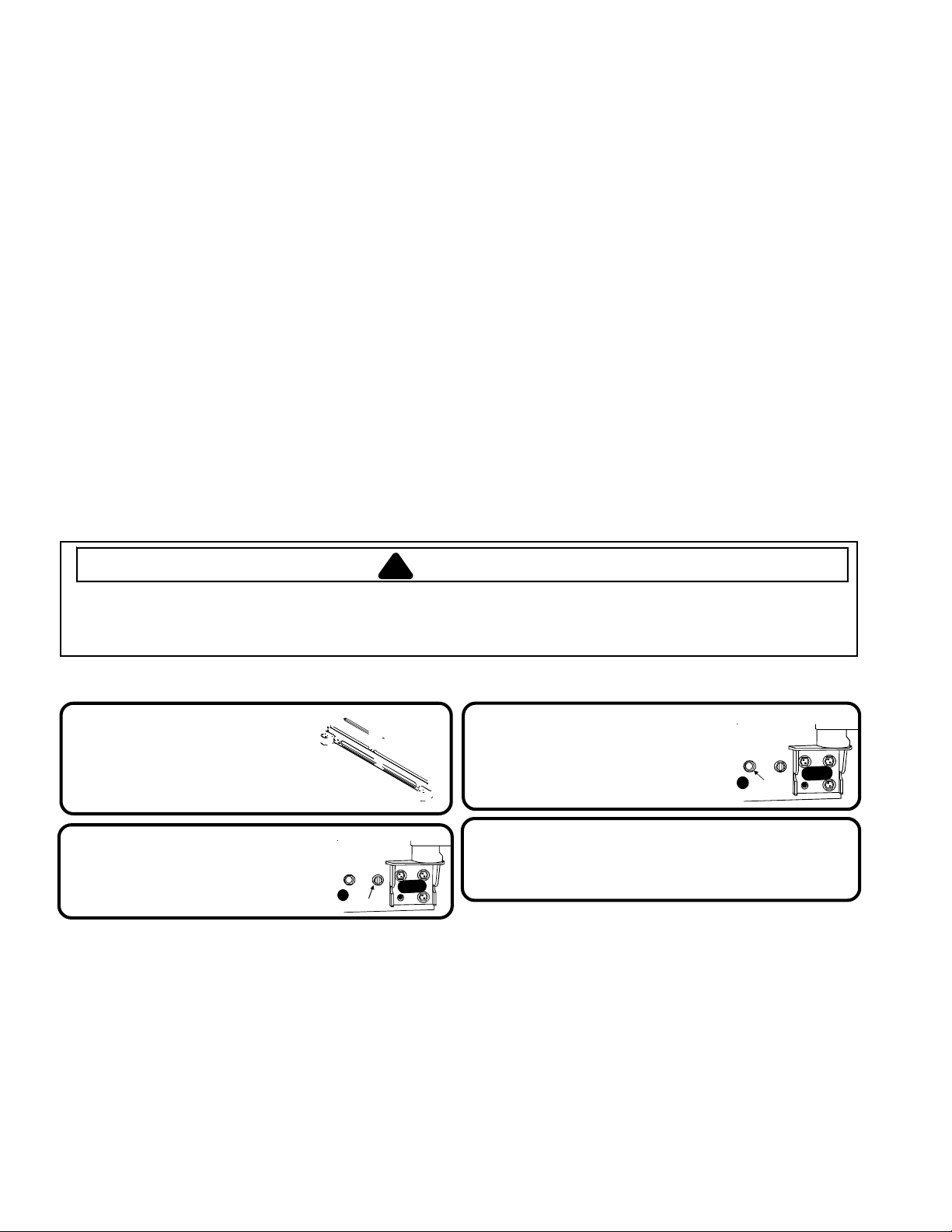
How to Remove Wooden Base
CAUTION
!
To avoid personal injury or property damage, two people must remove wooden base.
1. Tape doors shut to prevent doors from opening unexpectedly.
2. Slide appliance cart under side of refrigerator.
3. Wrap refrigerator with blanket or pad. Thread strap around refrigerator. Put foam shipping pads, located in shipping
carton, under strap. Tighten strap securely.
4. Lower appliance cart to floor with appliance cart handles on bottom.
5. Remove top two bolts from skid.
6. Return refrigerator and appliance cart to an upright position. Remove strap.
7. Slide appliance cart under opposite side of refrigerator.
8. Repeat steps 3–5.
9. Remove wooden base.
10. Return refrigerator and appliance cart to an upright position and remove appliance cart.
IMPORT ANT:
Do not leave refrigerator on its side longer than necessary to remove bolts.
How to Remove and Replace Doors and Hinges
• Contact a qualified engineer to perform this task.
4
Page 5
Installing Your Refrigerator
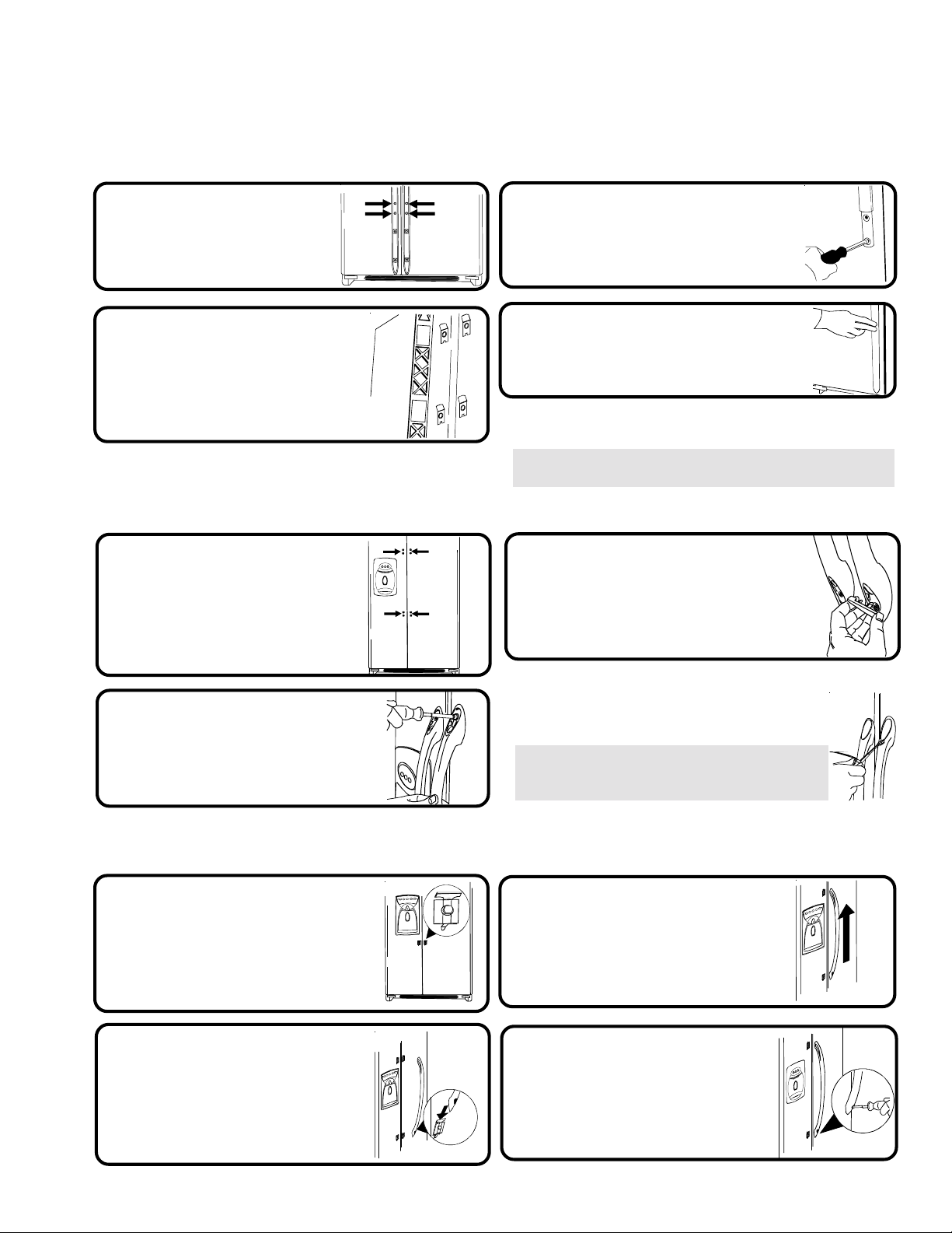
How to Install and Remove Handles
Handles are located within fresh food section of refrigerator. Trim, plugs, and accent pieces will be located within the
literature assembly.
Full-Length Grab Handles (non-stainless steel)
Remove two 1/4" hex nut
1
screws from bottom of
refrigerator
and freezer door.
Align door handles with top
2
and bottom sets of door clips,
and slide down until screw
holes on bottom of handles
match with door screw holes.
Half-Length Grab Handles (non-stainless steel)
Remove four 1/4" hex nut
1
screws from top and
bottom of doors.
Insert screws removed in step 1
3
into screw holes at bottom of
handle section.
Snap trim over bottom portion
4
of handles and retainers on
bottom of door
To remove after initial install...
• Follow steps 3 through 4 in reverse order.
NOTE: Fit may be tight. When removing handle, pull up and
out.
Snap colored handle trim over
3
screw holes at top and bottom of
handles.
• Snap in trim by inserting large round
end first.
Align door handles with
2
screw holes and insert screws
removed in step 1.
Stainless Steel Models
Loosen lower door clip on
1
refrigerator door with 1/4"
hex nut driver.
Locate predrilled hole at
2
base of handle, and fit
hollow end of handle over
lower door clip.
To remove after initial install...
Handles may need to be removed if transporting unit
through tight spaces.
• Follow steps 2 and 3 in reverse order.
IMPORTANT: To avoid damage to handle, use a
flat blade screwdriver edge wrapped in masking
tape to remove colored handle trim.
Fit other end of handle over
3
upper door clip and slide
up as far as possible.
Insert 1/4" hex nut
4
driver into predrilled hole at
base of handle and tighten
screw.
5
Page 6
Installing Your Refrigerator
How to Install the Handles continued
How to Connect the Water Supply
• Contact a qualified engineer to perform this task.
How to Level Your Refrigerator
CAUTION
!
• To avoid damage to walls and flooring, protect soft vinyl or other flooring with cardboard, rugs, or other protective material.
• To avoid damage or breakage to adjusting bolt, do not use power tools to correct leveling.
• DO NOT adjust unit to be any shorter than 173.9 cm tall (minus hinge and cap). Doing so may damage underside
components.
Materials Needed
•3/8" hex head driver • Level
Remove Toe Grille and
1
Bottom Hinge Covers
• Open both doors 180°, or as wide as
possible, to remove.
Turn both front adjustment
2
screws (A) clockwise to raise
and counterclockwise to
lower.
A
What if my doors are not aligned?
• Locate the higher door, and turn front adjustment screw
counterclockwise. Continue until doors are level.
• If bottom of adjustment range is reached, and doors are
not level–raise opposite door by turning front
adjustment screw clockwise.
• Replace toe grille
Turn both rear adjustment
3
screws (B) clockwise to raise
and counterclockwise to
lower.
Check with level to verify 6 mm tilt to the
4
back for proper door closure.
• If unit is aligned and stable, replace toe grille.
What if my unit rocks?
• Turn rear adjustment screw clockwise to raise
rocking corner.
• Replace toe grille.
B
6
Page 7
Installing Your Refrigerator
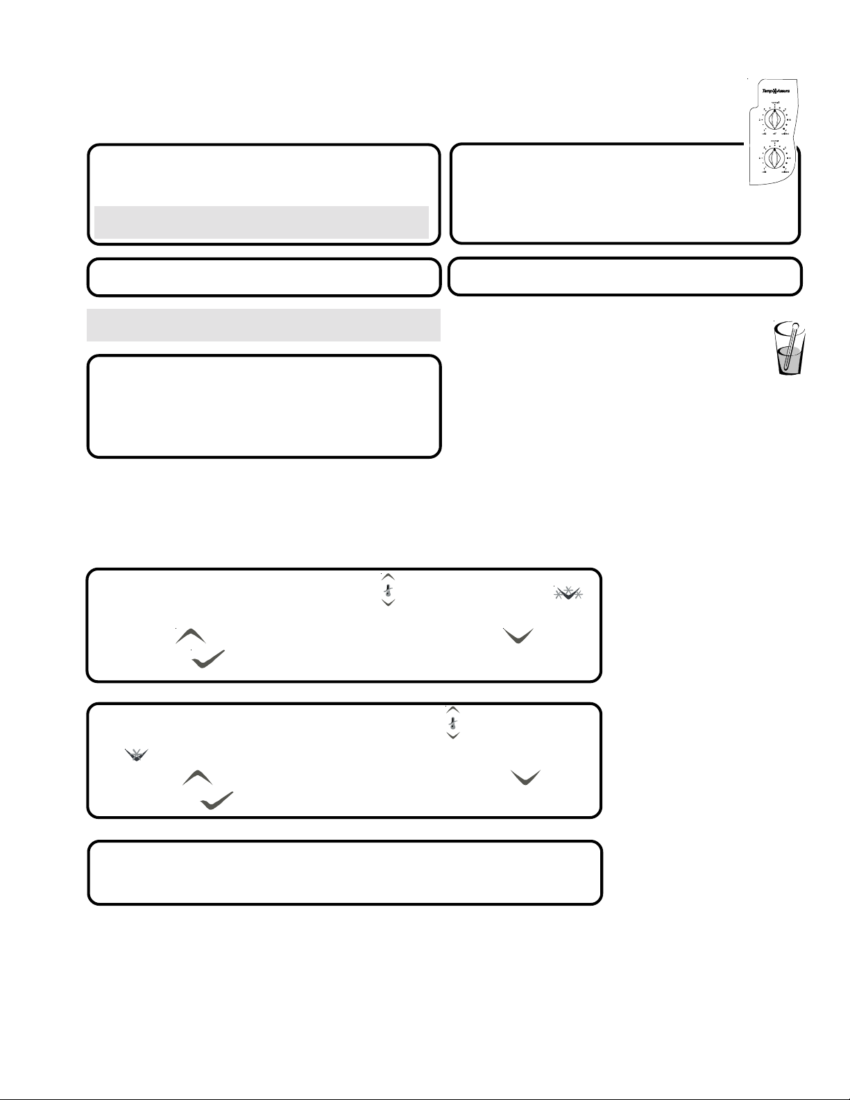
How to Adjust the Temperature Contr ols
This refrigerator is designed to operate at a household temperature of 16° to 43° C.
Locate refrigerator and freezer controls on
1
upper left wall of fresh food section, and
set both controls to 4.
IMPORTANT: Neither section will cool if freezer control is
set to Off.
Check to see that fresh food section
4
is 3° to 4° C.
• Turn control to next highest number if too warm.
• Turn control to next lowest number if too cold.
• Allow 5 to 8 hours for adjustments to take effect.
r
e
z
e
e
r
F
r
o
t
a
r
e
g
i
r
f
e
R
Allow 24 hours for temperatures to stabilize.
2
IMPORTANT: Due to design of unit, always start temperature
adjustments with freezer section.
Check to see if freezer temperature is -17°
3
to -16° C.
• Turn control to next highest number if too warm.
• Turn control to next lowest number if too cold.
• Allow 5 to 8 hours for adjustments to take effect.
Repeat process, as necessary.
5
How do I perform a temperature test?
Materials needed
• 2 thermometers measuring -21° to 10°C
• 2 drinking glasses
For Freezer
• Place thermometer in glass
of vegetable oil in middle
of freezer and continue
with step 3 of Temperature
Adjustment section.
Electronic Temperature Control Models
To set temperature of the freezer, use the buttons next to the
1
button. A setting of 0° to 2° F (-17° to -16° C) is recommended.
• Use the button to raise the temperature of the freezer section, or the to lower it.
• Press the
button to confirm the settings.
For Refrigerator
• Place thermometer in glass
of water in middle of unit
and continue with step 3
of Temperature Adjustment
section.
To set temperature of the fresh food section, use the buttons next to the
2
button. A setting of 38° to 40° F (3° to 4° C) is reommended.
• Use the button to raise the temperature of the fresh food section, or the to lower it.
• Press the button to confirm the settings.
Allow 24 hours for temperatures to stabilize.
3
NOTE: If adjusting the temperature of an operational unit, only 5 to 8 hours is
required for temperatures to take effect.
7
Page 8
About Your Filtration System...
Water Filter Removal and Installation
WARNING
!
To avoid serious illness or death, do not use unit where water is unsafe or of unknown quality without adequate
disinfection before or after use of filter.
CAUTION
!
• Bypass cartridge DOES NOT filter water. Be sure to have replacement cartridge available when filter change is required.
• If water filtration system has been allowed to freeze, replace filter cartridge.
• If system has not been used for several months, and water has an unpleasant taste or odor, flush system by dispensing
2–3 glasses of water. If unpleasant taste or odor persists, change filter cartridge.
Initial Install of Water Filter
Remove blue bypass cap and
1
retain for later use.
Remove sealing label from
2
end of filter and insert into
filter head.
• Rotate gently clockwise until filter stops
and snap filter cover closed.
Reduce water spurts by flushing air from
3
system. Run water continuously
(approximately 2 minutes) through
dispenser until water runs steady.
• Additional flushing may be required in some households
where water is of poor quality.
I'm trying to dispense water to
flush the system. Where's the water?
During initial use, allow about a 1 to 2 minute delay to
allow internal water tank to fill.
Replacing Water Filter
IMPORTANT: Air trapped in system may cause water and
cartridge to eject. Use caution when removing.
Turn filter counterclockwise until it
1
releases from filter head.
Drain water from filter into sink or toilet,
2
and dispose in normal household garbage.
Wipe up excess water in filter cover and
3
continue with installation steps 2 and 3.
When do I change the water filter?
Select dispenser models feature a water filter change indicator.
For instructions on how to operate and reset this feature, refer
to the dispenser features section in your manual.
For units without indicator feature, filter should be changed
approximately every 6 months.
IMPORTANT: Condition of water and amount used
determines life span of water filter cartridge. If water use is
high, or if water is of poor quality, replacement may need to
take place more often.
What if I choose not to use the water
filtration system?
Dispenser feature may be used without water filter cartridge.
If you choose this option, replace filter with blue bypass
cap.
How do I order a replacement filter
cartridge?
Replacement Water Filter cartridge model OWF51
is available through your dealers and servicers. Contact
your local distributor for more information.
8
Page 9

Fresh Food Features
9
Page 10

Fresh Food Features
A
Door Storage
Dairy Center
The dairy center provides convenient storage
for items such as butter, yogurt, cheese, etc.
This compartment is an adjustable feature
located in the door. It can be moved to
several different locations to
accommodate storage needs.
• To remove, slide dairy center
up and pull straight out.
• To install, reverse above
procedure.
Tilt-Out Door Buck ets
(some models)
The Tilt-Out Bucket assembly consists of a bucket and
frame, providing adjustable, convenient storage for
food items in door. The bucket assembly tilts forward
for easy access of items, and lifts out for ease in
cleaning and adjusting.
T o remove and install bucket:
• To remove bucket, tip bucket
forward and pull straight out
to remove.
• To install bucket, slide bucket
into bucket frame and push
bucket upright.
Beverage Chiller™/
Mini-Chiller™
The Temperature-Controlled Beverage Chiller™ and
Temperature-Controlled Mini Beverage Chiller™ keep
beverages and other items up to 3°C colder than the
rest of the fresh food section. Air inlet allows air from
the freezer section to pass to Beverage Chiller™.
The Beverage Chiller™ control is located
on the left wall of fresh food section.
Control adjusts amount of air circulating in
Beverage Chiller™. Turn control toward the
large snowflake icon for colder temperature.
To remove and inst all Beverage Chiller™:
• If located directly above Chiller,
dairy center or door bucket may
need to be removed. Refer to
appropriate instructions and
remove item. Slide Beverage
Chiller™ assembly up and pull
straight out.
• To install, align one of the
Beverage Chiller™ cold air
intake holes (A) with one of
the two air inlets (B) in door
liner. Push assembly down
onto door liner retainer until
it stops.
(some models)
B
T o adjust bucket frame:
• Remove bucket per above instructions.
• Lift frame off door support and place in desired
door location.
Grip Pads
The Grip Pads prevent objects
from sliding in the door bucket.
Grip Pads are removable and are
top-rack dishwasher safe for easy
cleaning.
IMPORTANT: Beverage Chiller™ will not operate
properly if air intake holes are not aligned with air
inlet in door liner.
Door Buckets
Door buckets adjust to meet
individual storage needs.
• To remove, slide bucket up and
pull straight out.
• To install, reverse above procedure.
10
Page 11

Drawers
Deli/Crisper Drawer climate controlled
The Deli/Crisper system provides a drawer with a
variable temperature control that keeps the
compartment up to 3°C colder than refrigerator
temperature. This drawer can be used for deli storage
or additional produce storage.
NOTE: Cold air directed to the Deli/Crisper System
can decrease refrigerator temperature. Refrigerator
control may need to be adjusted.
Controls
Located on the wall to the left of the drawer, the
climate controls regulate the air temperature in the
Deli/Crisper drawer. Set control level to cold to provide
normal refrigerator temperature for produce with outer
skins. Use the coldest setting for meats or other deli
items.
Crisper Drawer climate controlled
Garden Fresh™ crisper keeps produce fresh longer
by providing an environment with adjustable humidity.
Controls
The Garden Fresh™ controls regulate the amount of
humidity in the crisper drawer. Use the low setting for
produce with outer skins. Use the high setting for leafy
produce.
Fresh Food Features
T o remove and install drawers:
• To remove drawer, pull drawer out
to full extension. Tilt up front of
drawer and pull straight out.
• To install, reverse above
procedure.
T o remove and install crisper shelf:
• Lift off wall supports and remove.
• To install shelf, lower shelf onto wall supports
and push in until shelf is flush with rear wall.
11
Page 12

Freezer Features
Automatic Dispensing Ice Maker
This ice maker creates the ice used in the dispensing
system.
Using Ice Maker for the First Time
• Confirm ice bin is in place
and ice maker arm is down.
• After freezer section reaches
between -18° to -17° C, ice
maker fills with water and
begins operating.
• Allow approximately 24 hours
after installation to receive first harvest of ice.
• Discard ice created within first 12 hours of
operation to verify system is flushed of impurities.
Operating Instructions
• Confirm ice bin is in place and ice maker arm is
down.
• After freezer section reaches -18° to -17° C, ice
maker fills with water and
begins operating. You will
have a complete harvest
of ice approximately every
3 hours.
• Stop ice production by
raising ice maker arm until
click is heard.
• Ice maker will remain in the off position until arm is
pushed down.
Ice Cream Shelf
The Ice Cream Shelf provides a space for items to be
chilled or frozen quickly.
• To remove, lift Ice Cream Shelf
from ice bin rails and pull
straight out.
• To install, reverse above
procedure.
Ice Storage Bin
The ice storage bin is located below the automatic
dispensing ice maker.
T o remove and install ice storage bin:
• To remove bin, remove Ice Cream
Shelf. Raise ice maker arm to
deactivate ice maker.
• Lift front of bin and pull out to its full extension. Lift up
front of bin and remove.
• To install, slide bin into rails below ice maker until
bin locks into place. Drop ice maker arm to activate
ice maker, and replace Ice Cream Shelf.
IMPORT ANT: Ice bin must
be locked in proper place for
proper ice dispensing. If freezer
door does not close, bin is not
in proper location. Turn auger
driver as shown to properly align
ice bin with back of unit.
12
Page 13

Shelves
Stor-Mor® System
Baskets slide out for easy access of items in back.
Shelves can be removed to meet individual storage
needs.
®
T o remove and install Stor-Mor
• To remove, snap right side of
shelf from cabinet railing and
remove from wall mounting
clips.
• To install, reverse above procedure.
NOTE: Back of shelf must be flush with back of
cabinet to secure firmly in cabinet railing. Improper
alignment will cause shelf to slide.
T o remove and install basket s:
• To remove, pull basket forward
to full extension. Lift front handle
to release basket from rails and
remove.
• To install, reverse above procedure.
shelf:
Freezer Features
Door Storage
13
Page 14

Dispenser Features
Primary Features
Dispenser Light not shown
A light activates within the dispenser area at full power when dispensing ice or water.
Front Fill Button (some models)
14
Page 15

Dispenser Features
Control Features
(Five button control)
Ice Dispenser Operation
To dispense ice:
• Select Cubed or Crushed ice mode by pushing button on dispenser control panel. A green
indicator light above button shows mode selection.
• Press container against dispenser pad. When dispensing crushed ice, hold container as close
to chute as possible to reduce spraying. Selection mode may not be changed while ice dispenser
is in operation.
NOTE: If dispenser is active for more than 3 minutes, an automatic lock out sensor will shut down power
to dispenser area. See Automatic Lock Out for further information.
Dispenser Lock
This feature prevents ice or water from being dispensed.
To lock and unlock dispenser:
• To lock dispenser, press and hold Dispenser Lock button for
3 seconds. A green indicator light above button confirms
dispenser is locked.
• To unlock dispenser, hold Dispenser Lock button for 3 seconds.
Green indicator light above button will go out.
What is the Automatic Lock Out feature?
The Automatic Lock Out feature shuts down power to the
water and ice dispenser when either dispenser has run
continuously for approximately 3 minutes. If this mode goes
into effect, the green light will activate above the Dispenser
Lock button.
To unlock dispenser:
• T o unlock dispenser, hold Dispenser Lock button for 3
seconds. Green indicator light above button will go out.
Filter Status Indicator Light
The Filter Status Indicator Light serves as a reminder to replace the water filter. A green light indicates that the
filter is in good condition. A red light indicates the filter should be changed. Once light turns red, it will remain
red until function is reset.
To reset indicator:
• Press and hold both Dispenser Lock and Water buttons simultaneously for 4 seconds. The green Filter Status
Indicator Light will flash 3 times when the function has successfully reset.
Auto Light
The Auto Light function offers the ability to activate the dispenser light at half-power when the Light Sensor
detects that the light levels in room are low.
To activate and deactivate Auto Light:
• To activate, press Auto Light button located on control panel. A green
indicator light above button displays to show that sensor is active.
• To deactivate, press Auto Light button. Green indicator light will go out.
NOTE: Dispenser light will operate whether
or not Auto Light is selected.
Sabbath Mode (some models)
This mode is intended to deactivate power to the LED and dispenser lights,
while allowing the controls to remain operational.
To activate Sabbath Mode:
• Press and hold both Dispenser Lock and Auto Light buttons simultaneously
for 3 to 4 seconds. After 3 to 4 seconds, the LED and dispenser lights will turn
off. Dispenser light will not activate during dispensing while in this mode.
To deactivate Sabbath Mode:
• Press and hold both Dispenser Lock and Auto Light buttons simultaneously for 3 to 4 seconds. After 3 to 4 seconds,
the LED and dispenser lights will activate.
NOTE: In the event that power is
interrupted while the Sabbath Mode
is active, the control will remain in
Sabbath Mode when power returns.
+
15
Page 16

Dispenser Features
Control Features
(Electronic control)
Water and Ice Dispensing (main activator)
The water and ice dispensing functions work independently of each other.
T o dispense water:
To dispense ice:
• Press the
button
• Press water activator
• Press the
• Press the
button for crescent ice.
button for crushed ice.
Dispenser Lock
This feature prevents ice or water from being dispensed.
T o lock and unlock dispenser:
• To lock dispenser, press and hold the button for 3 seconds. A green indicator light above button confirms dispenser
is locked.
• To unlock dispenser, hold the button for 3 seconds. Green indicator light above button will go out.
Light Function
The Light function offers offers two setting: OFF and AUTO.
The OFF setting allows the light to function only as a dispenser cavity light.
The AUTO setting allows the SENSOR to measure the surrounding light levels and adjust the power of
the cavity light accordingly. When the sensor registers lower light levels (night time, darkened kitchen), the cavity light will
respond at 50% power. When the sensor registers high light levels (lighted kitchen, direct sunlight), the cavity light will not
activate.
T o deactivate the AUTO setting:
• Press the
function only when dispensing ice or water.
• To activate the AUTO setting, press the
cavity dispenser light will use the AUTO setting.
button located on control panel. When the green indicator light above button display is off, the light will
button. When the green indicator light above the button display is on, the
NOTE: Dispenser light will operate at full
power when ice or water functions are in use.
Filter Status Indicator Light
The Filter Status Indicator Light serves as a reminder to replace the water filter. A green light indicates that the
filter is in good condition. A red light indicates the filter should be changed. Once light turns red, it will remain red
until function is reset.
T o reset indicator:
• Press and hold both the
will flash 3 times when the function has successfully reset.
and the buttons simultaneously for 4 seconds. The green Filter Status Indicator Light
What is the Automatic Lock Out feature?
The Automatic Lock Out feature shuts down power to the water and ice dispenser when either dispenser has run continuously for approximately
2 minutes. If this mode goes into effect, the green light will activate above the
To unlock dispenser:
• T o unlock dispenser , hold
button for 3 seconds. Green indicator light above button will go out.
button.
16
Page 17

Dispenser Features
Temper ature Keys
These keys will lower or raise the freezer or fresh food compartment temperature.
T o set the fresh food temperature:
• Press the
Control Features continued
(Electronic control)
button to confirm the setting.
• Locate the
button to raise the temperature of the fresh food
section, or the to lower it.
Max Cool
This function causes the fresh food temperature to drop to the Minimum Refrigerator Temperature Setting preset
by the control. This setting remains in effect for approximately 10 hours.
T o activate Max Cool:
• Press the
button will indicate active status.
Max Freeze
This function causes the freezer temperature to drop to the Minimum Freezer Temperature Setting preset by
the control. This setting remains in effect for approximately 24 hours.
T o activate Max Freeze:
• Press the button. The green light above the
button will indicate active status.
next to the button. Use the
NOTE: The temperature setting cannot be changed if Max Cool or Max Freeze setting is active.
button. The green light above the
NOTE: The temperature setting cannot be changed if Max Cool or Max Freeze setting is active.
To set the freezer temperature:
• Repeat the above instructions with the
the
To deactivate Max Cool:
• Press the
turn off.
T o deactivate Max Freeze:
• Press the
button will go out.
button on the display.
button. The green light above the button will
button. The green light above the
buttons next to
Display On/Off
The Display On/Off switch controls power to the LED display.
To deactivate display:
• Press the button. The display will turn off.
To reactivate display:
• Press the button. The display will turn back on.
Vacation Mode
This key, if enabled, causes less frequent defrost cycles. This conserves energy.
T o place refrigerator into Vacation Mode:
• Press the button.
Alarm Off
This key is used to turn the HI TEMP Warning Indicator and
audio alarm, as well as the OPEN DOOR audio
alarm off.
T o deactivate Vacation Mode:
• Press the button, or open either refrigerator door.
To turn the alarm off:
• Press the
17
button.
Page 18

Dispenser Features
Hidden Control Features (Electronic Control)
Sabbath Mode
This mode is intended to deactivate power to the LED and dispenser lights, while allowing the
controls to remain operational. No visual or audio alarms will be available while in this mode.
T o activate Sabbath Mode:
• Press and hold both the
simultaneously for 3 seconds. After 3 seconds, the
LED and dispenser lights will turn off. Dispenser
light will not activate during dispensing while in
this mode.
and buttons
NOTE: In the event that power is interrupted while the Sabbath Mode is active, the control will remain in
Sabbath Mode when power returns.
T o deactivate Sabbath Mode:
• Press and hold both
seconds. After 3 seconds, the LED and dispenser lights will
activate.
and buttons simultaneously for 3
Auto Display
The AUTO Display controls the illumination of the LED display based on the light readings received from the SENSOR.
In AUTO mode, if the SENSOR indicates low light levels, the display will be dimmer than if displaying during well-lit
periods. In ON mode, the display will have only one illumination setting and will not change due to light levels.
T o set the power level of the display:
+
• Press and hold both the
the display by using
• Use the refrigerator
• Activate the chosen setting by pressing the
O for on, AL for auto.
Temper atur e Conver sion Mode
This mode is available to change the Temperature
Display between Fahrenheit and Celsius.
button and the freezer button for 3 seconds. The current active state will show in
button to scroll through the display states.
button.
T o change temperature reading:
• Press the
for 3 seconds. Pressing the same button combination will allow
the user to toggle between the two selections .
and freezer buttons simultaneously
Hidden Lockout for Upper Keypad
The purpose of this mode is to prevent tampering with the upper set of dispenser controls.
This includes the Display On/Off , Max Freeze, Max Cool, Vacation Mode, and Temperature Set
functions.
To activate Hidden Dispenser Lockout:
• Press the
3 seconds.
and buttons simultaneously for
To deactivate Hidden Dispenser Lockout:
• Press the
for 3 seconds.
and buttons simultaneously
° F
° C
+
ON/OFF Function
The ON/OFF function turns off cooling to the
fresh food and freezer sections.
To turn the unit off:
• Press the freezer button until the readout registers
beyond the maximum allowable freezer temperature. At
this point, the LED displays:
• Press the button to confirm the selection.
-- --
WARNING
!
To avoid electrical shock which can cause severe personal
injury or death, do not perform maintenance or service on
refrigerator unless unit is unplugged.
To reactivate the unit:
• Press the freezer
• Press the
button to confirm the selection.
button.
18
Page 19

How to Clean Your Unit
WARNING
!
To avoid electrical shock which can cause severe personal injury or death,
disconnect power to refrigerator before cleaning. After cleaning, connect power.
CAUTION
!
To avoid personal injury or property damage:
• Read and follow manufacturer's directions for all cleaning products.
• Do not place buckets, shelves, or accessories in dishwasher. Cracking or
warping of accessories may result.
• Handle tempered glass shelves carefully. Shelves may break suddenly if
nicked, scratched, or exposed to sudden temperature change.
• Protect soft vinyl or other flooring with cardboard, rugs, or other protective
material.
Hints and Care
General
1. Wash surfaces with a warm water and baking soda solution. Use a soft clean
cloth to clean surfaces.
2. Rinse surfaces with warm water. Dry surfaces with a soft, clean cloth.
Adhesives
1. Remove glue residue by rubbing toothpaste into adhesive with fingers until
adhesive loosens.
2. Rinse surface with warm water. Dry surface with a soft, clean cloth.
Door Gaskets
1. Keep gaskets clean at all times. Clean door gaskets thoroughly every 3 months
according to “General” instructions.
Condenser Coils
Clean condenser coil every 3 months to ensure maximum performance of
refrigerator. Accumulated dust and lint may cause the following:
• reduced cooling performance
• increased energy usage
• in extreme cases, premature compressor failure
1. Remove toe grille and bottom hinge covers as
shown right.
2. Clean front surface of condenser coil with a vacuum cleaner hose nozzle.
3. Replace toe grille by inserting clips in holes and snapping in. Snap bottom
hinge covers over bottom hinges.
Glass Shelves
Remove shelf by lifting front, releasing hooks from metal track then pulling out.
Place shelf on a towel. Allow shelf to adjust to room temperature before cleaning.
Clean crevices by completing the following steps:
1. Dilute mild detergent and brush solution into crevices using a plastic bristle
brush. Let set for 5 minutes.
2. Spray warm water into crevices using faucet spray attachment.
3. Dry shelf thoroughly and replace shelf by inserting hooks into metal track and
lowering front.
19
Page 20

Hints and Care
A
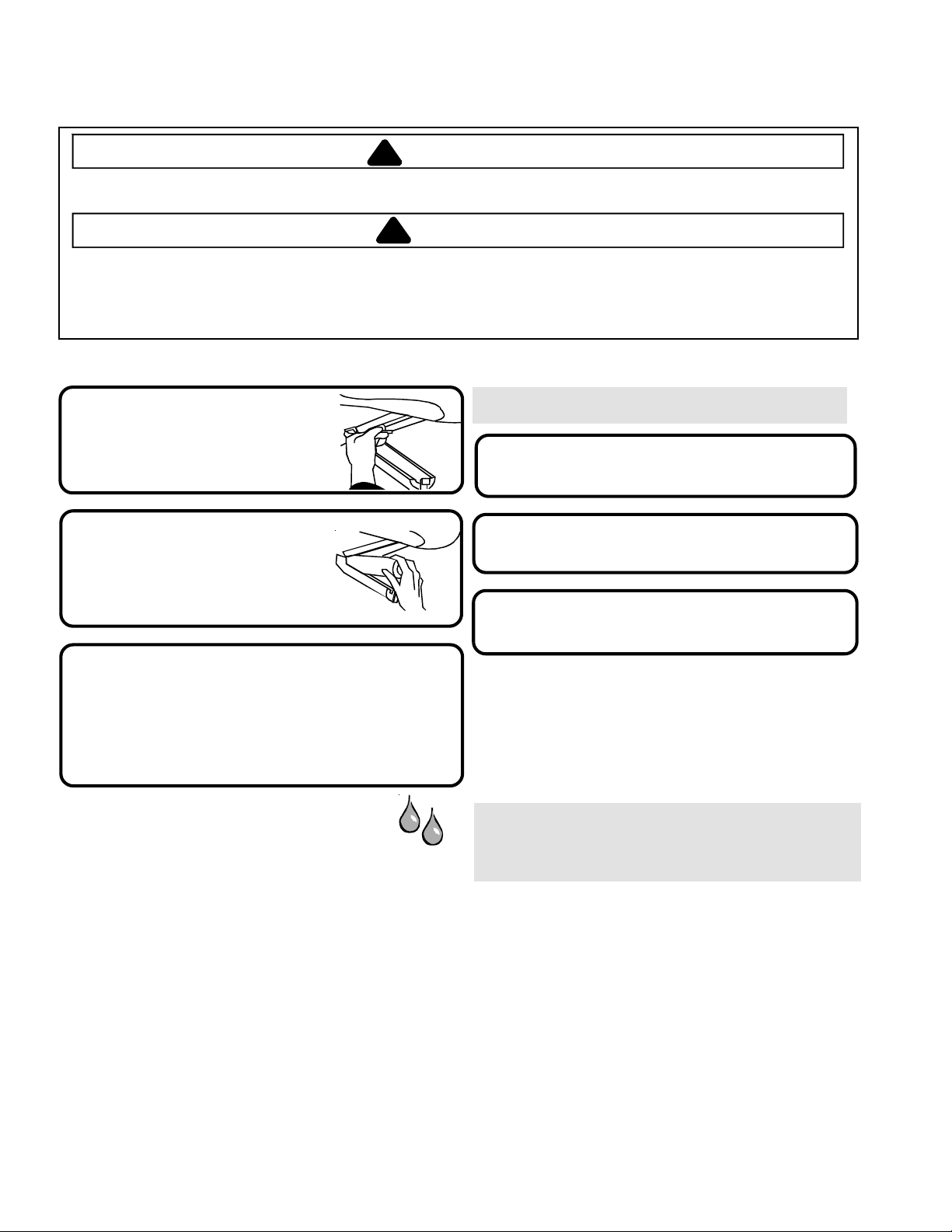
How to Remove and Replace Light Bulbs
WARNING
!
To avoid electrical shock which can cause severe personal injury or death,
disconnect power to refrigerator before replacing light bulb. If unable to
disconnet power by unplugging power cord then remove the fuse at mains.
After replacing light bulb, connect power.
CAUTION
!
To avoid personal injury or property damage, observe the following:
• Allow light bulb to cool.
• Wear gloves when replacing light bulb.
Upper fresh food section
1. Locate finger gaps on each side of clear light
shield. Insert fingers and press in on each side
of shield. Pull shield down and remove.
2. Remove light bulbs.
3. Replace with appliance bulbs, type Krypton E27,
no greater than 25 watts.
4. Replace light bulb cover by inserting front tabs of
light shield into holes in liner directly in front of light assembly.
5. Snap back of light cover into place.
Lower fresh food section and
Non-dispensing model freezer section
1. Pinch bottom tabs (A) on light cover and pull straight
out.
2. Remove light bulb.
3. Replace with appliance bulbs, type Krypton E27,
no greater than 25 watts.
4. Insert top tabs (B) of light cover into refrigerator liner and
snap bottom portion over light assembly.
B
Dispensing model freezer section
1. Remove ice bin by lifting front of bin and pulling out.
2. Remove light bulb cover by pinching top tab (A) and
pulling cover out of liner.
3. Replace with appliance bulbs, type Krypton E27,
no greater than 25 watts.
4. Insert bottom tab (B) of light cover into liner and snap
top portion over light assembly.
5. Replace ice bin by sliding in until bin locks into place.
A
B
Ice ’N Water dispenser
1. Locate light bulb inside top edge of dispenser frame. Unscrew to remove.
2. Replace bulbs with a 230/240VAC bulb no greater than 12 watts. Extra
light bulbs are provided in crisper due to local unavailability.
20
Page 21

Before Calling Service
Today’ s refrigerators have new features and are more ener gy efficient. Foam insulation is very energy efficient and has
NOISE
TOPIC POSSIBLE CAUSE SOLUTION
excellent insulating capabilities, however, foam insulation is not as sound absorbent. As a result, certain sounds may be
unfamiliar. In time, these sounds will become familiar . Please refer to this information before calling service.
Clicking
Air rushing or
whirring
Gurgling or
boiling sound
Thumping
Vibrating noise
Buzzing Ice maker water valve (J) hookup (some
Humming
Freezer control (A) clicks when starting or
stopping compressor.
Defrost timer (B) sounds like an
electric clock and snaps in and out
of defrost cycle.
Freezer fan (C) and condenser fan (D)
make this noise while operating.
Evaporator (E) and heat exchanger (F)
refrigerant makes this noise when flowing.
Ice cubes from ice maker(some models)
drop into ice bucket (G).
Dispenser ice chute (H) closing. Normal operation
Compressor (I) makes a pulsating sound
while running.
Refrigerator is not level.
models) buzzes when ice maker fills
with water.
Ice maker (K) is in the ‘on’ position without
water connection.
Ice auger (L) (some models) hums as
auger agitates ice during dispensing.
Compresser (I) can make a high pitched
hum while operating.
Solenoid valve (M) operating ice
chute door.
OPERATION
Freezer control
and lights are on,
but compressor
is not operating.
Deli/Crisper
system
temperature
is too warm
Refrigerator does
not operate
Refrigerator still
won’t operate
Fresh food
temperature is
too cold
Refrigerator is in defrost mode.
Control settings are too low. See section on Deli/Crisper system to adjust controls.
Freezer controls are set too low.
Drawer is improperly positioned.
Refrigerator is not plugged in. Plug in unit.
Freezer control is not on. See section on controls in your Owner’s Manual.
Fuse is blown, or circuit breaker needs
to be reset.
Power outage has occurred Call local power company listing to report outage.
Unit is malfunctioning.
Condenser coils are dirty.
Refrigerator or freezer controls are set
too high.
Beverage Chiller™ (some models) is
improperly positioned.
Normal operation
Normal operation
Normal operation
Normal operation
Normal operation
Normal operation
See Installation
Instructions for details
on how to level your unit.
Normal operation
Stop sound by raising ice
maker arm to ‘off’ position.
See Automatic Ice Maker
section in your owner’s
manual for details.
Normal operation
Normal operation
E
D
F
I
J
C
Normal operation
Normal operation Wait 40 minutes to see if refrigerator
restarts.
See controls section in Owner’s Manual on how to adjust
your controls.
See section on Deli/Crisper system to verify drawer
positioning.
Replace any blown fuses. Check circuit breaker and reset
if necessary.
Unplug refrigerator and transfer food to another unit. If
another unit is not available, place dry ice in freezer
section to preserve food. Warranty does not cover
food loss . Contact service for assistance.
Clean according to cleaning instructions in your
Owner’s Manual.
See controls section in Owner’s Manual on how to adjust
your controls.
See section on Temperature-Controlled Beverage Chiller™
to verify proper positioning.
21
K
G
L
H
M
B
A
Page 22

Before Calling Service
OPERATION
TOPIC POSSIBLE CAUSE SOLUTION
Food temperature
appears too warm
Refrigerator has an odor
Water droplets form on
outside of refrigerator
Water droplets form on
inside of refrigerator
Refrigerator or ice maker
make unfamiliar sounds
or seems too loud
Deli/Crisper System and/or
crisper drawers do not
close freely
Refrigerator runs
too frequently
Door is not closing properly.
Controls need to be adjusted.
Condenser coils are dirty.
Rear air grille is blocked on models
over 60 cm deep.
Door has been opened frequently,
or has been opened for long periods
of time.
Food has recently been added.
Compartment is dirty or has odorcausing food.
Air filter (some models) needs to
be changed.
Check gaskets for proper seal.
Humidity levels are high. Normal during times of high humidity.
Controls require adjustment
Humidity levels are high or door has
been opened frequently.
Check gaskets for proper seal.
Normal operation
Contents of drawer, or positioning of
items in the surrounding compartment
could be obstructing drawer
Drawer is not in proper position
Refrigerator is not level. See Installation Instructions for details on how to level your unit.
Drawer channels are dirty or
need treatment.
Doors have been opened frequently
or have been opened for long periods
of time.
Humidity or heat in surrounding area
is high.
Food has recently been added.
Unit is exposed to heat by
environment or by appliances nearby.
Condenser coils are dirty.
Refrigerator is not level. See Installation Instructions for details
on how to level your unit.
Check gaskets for proper seal. Clean, if necessary, according to
cleaning instructions in Owner’s Manual.
Check for internal obstructions that are keeping door from
closing properly (i.e. improperly closed drawers, ice buckets,
oversized or improperly stored containers or foodstuffs, etc.).
See the controls section in your Owner’s Manual for assistance
in how to adjust your controls.
Clean according to cleaning instructions in your
Owner’s Manual.
Check the positioning of food items in refrigerator to make
sure grille is not blocked. Rear air grille is located behind
crisper drawers.
Reduce time door is open. Organize food items efficiently to
assure door is open for as short a time as possible.
Allow interior environment to adjust for period the door has
been open.
Allow time for recently-added food to reach refrigerator or
freezer temperature.
Refer to odor removal instructions in Owner’s Manual.
Change air filter.
Clean, if necessary, according to cleaning instructi ons i n
Owner’s Manual.
See the controls section in your Owner’s Manual for assistance
in how to adjust your controls.
See the controls section in your Owner’s Manual for assistance
in how to adjust your controls.
Reduce time door is open. Organize food items efficiently to
assure door is open for as short a time as possible.
Clean, if necessary, according to cleaning instructi ons i n
Owner’s Manual.
Refer to “Noise” section of Before Calling Service in your
Owner’s Manual.
Reposition food items and containers to avoid interference with
the drawers.
See section on Deli/Crisper System and/or crisper drawer
section for proper placement.
Clean drawer channels with warm, soapy water. Rinse and
dry thoroughly.
Apply a thin layer of petroleum jelly to drawer channels.
Reduce time door is open. Organize food items efficiently to
assure door is open for as short a time as possible.
Allow interior environment to adjust for period the door has
been open.
Normal operation
Allow time for recently-added food to reach refrigerator or
freezer temperature.
Evaluate your unit’s environment. Unit may need to be moved
to run more efficiently.
Clean according to cleaning instructions in your
Owner’s Manual.
22
Page 23

Before Calling Service
OPERATION (continued)
TOPIC POSSIBLE CAUSE SOLUTION
Refrigerator runs too
frequently (continued)
ICE & WATER
Water appears cloudy
Particles in wate r and/or
ice cubes.
No indicator lights are lit
on dispenser control
(some models)
Neither ice nor water is
dispensed when pads are
pushed (some models)
Ice maker is not producing
enough ice or ice is
malformed (some models)
Ice maker is not producing
ice (some models)
Controls need to be adjusted.
Door is not closing properly
Air or air bubbles in water.
Carbon dust from water filter cartridge.
Concentrations of minerals in water will
form particles when water becomes frozen
and melts.
Freezer door is not closed.
Refrigerator is not plugged in. Plug in unit.
Fuse is blown, or circuit breaker needs to
be reset.
Power outage has occurred. Call local power company listing to report outage.
Freezer door is not closed. Verify that freezer door is closed. Power is removed from the
Controls are in lock m ode. See Dispenser control instructions.
Water tank is filling. At initial use, there is an approximate 45-second delay in
Ice maker or ice maker-equipped unit has just
recently been installed or a large amount of ice
has just been used.
Water filter is clogged or needs to be changed. Change water filter.
Ice maker has just recently been installe d or a
large am ount of ice ha s just been used.
Water pre s sure is too low. Low water press ure can caus e v alve to leak . W ater press ure
Water filter is clogged or needs to be changed. Change water filter.
Ice maker arm is not in correct position Confirm ice maker arm is down. See Automatic Ice Maker
Household water supply is not reaching
water valve
Water supply tubing has kinks. Turn off water supply and remove kinks. If kinks cannot be
Water pressure is too low. Water pressure must be between 20 to 100 pounds per square
Check freezer temperature. See the controls section in your Owner’s Manual for assistance
Ice bin is not installed properly See ice bin section for proper installation and alignment.
See the controls section in your Owner’s Manual for
assistance in how to adjust your controls.
Refrigerator is not level. See Installation Instructions for
details on how to level your unit
Check for internal obstructions that are keeping door
from closing properly (i.e. improperly closed drawers,
ice buckets, oversized or improperly stored containers
or foodstuffs, etc.).
Check gaskets for proper seal. Clean, if necessary,
according to cleaning instructions in Owner’s Manual.
This is normal when first using dispenser and will
disappear with use.
Initial water ejected through cartridge may contain
harmless carbon dust flushed from cartridge. Particles are
safe for consumption. Will disappear after the first few
uses.
Particles are not harmful and naturally occur in
water supplies.
Verify that freezer door is closed. Power is removed from
the control when freezer door is opened.
Replace any blown fuses. Check circuit breakers for any
tripped circuits.
control when freezer door is opened.
dispensing while the internal water tank is filling.
Wait 24 hours for ice production to begin and for ice make r to
restock after emptied.
Wait 24 hours for ice production to begin and for ice make r to
restock after emptied.
must be between 20 to 100 pounds per square inch to function
properly. A minimum pressure of 35 pound s per squa re inc h is
recommended for units with water filters.
section in your Owner’s Manual for details.
Check water connection procedure in your Installation
Instructions.
removed, replace tubing.
inch to function properly. A minimum pressure of 35 pounds
per square inch is recommended for units with water filters.
on how to adjust your c ontrols. Freezer must be between 0 to
2°F (-18 to –17°C) to produce ice.
23
Page 24

Before Calling Service
ICE & WATER
TOPIC POSSIBLE CAUSE SOLUTION
Ice maker is not producing
ice (some models-continued)
Unit is leaking water
Ice forms in inlet tube to
ice maker
Water fl ow is slow er
than normal
Dispenser water is not cold
Improper water valve was installed. Check water connection procedure in your Installation
Plastic tubing was used to complete
water connection.
Improper water valve was installed.
Water pressure is low.
Freezer temperature is too high.
Water pressure is low.
Improper water valve was installed.
Water inlet tubing has kinks.
Water filter is clogged or needs to
be changed.
Refrigerator has been recently installed
Water supply in holding tank has
been depleted.
Water has settle into water lines outside
holding tank and has warmed to
room temperature.
Instructions. Se lf-piercing and
low water pressur e and may clog the line over time. The
manufacturer is not responsible for prope rty damage
due to improper installation or water c onne c ti on.
The manufacturer recommends using copper tubing
for installation. Plastic is l ess durabl e and can cause
leakage. The manufacturer is not responsible for
property damage due to improper installation or
water connection.
Check water connection procedure in your Installation
Instructions. Self-piercing and
low water pressure and may clog the line over time. The
manufacturer is not responsible for property damage
due to improper installation or water connection.
Water pressure must be between 20 to 100 pounds per
square inch to function properly. A minimum pressure of
35 pounds per square inch is recommended for units with
water filters.
See the controls section in your Owner’s Manual for
assistance on how to adjust your controls. Freezer is
recommended to be between 0 to 2°F (-18 to –17°C).
Water pressure must be between 20 to 100 pounds per
square inch to function properly. A minimum pressure of
35 pounds per square inch is recommended for units with
water filters.
Check water connection procedure in your Installation
Instructions. Self-piercing and
low water pressure and may clog the line over time. The
manufacturer is not responsible for property damage
due to improper installation or water connection.
Turn off water supply and remove kinks. If kinks cannot be
removed, replace tubing.
Change water filter.
Allow approximately 12 hours for water in holding tank
to chill.
Discard first glass of water and refill.
3
/16” saddle valves cause
3
/16” saddle valves cause
3
/16” saddle valves cause
24
Page 25

Water Filter Data
System Specification and Performance Data Sheet
Refrigerator Water Filter Cartridge Model OWF51
Specifications
Service Flow Rate (Maximum) ............................................. 0.75 GPM (2.83 L/min)
Rated Service Life OWF50-NI300 (Maximum) ..................... 300 gallons/ 1135 liters
Rated Service Life OWF50-WI500 (Maximum) ..................... 500 gallons/ 1892 liters
Maximum Operating Temperature........................................ 100° F/38° C
Minimum Pressure Requirement .......................................... 35 psi/ 138 kPa
Minimum Operating Temperature......................................... 33° F/ 1° C
Maximum Operating Pressure .............................................. 120 psi/ 827 kPa
General Use Conditions: Read this Performance Data Sheet and compare the capabilities of this unit with your actual
water treatment needs.
DO NOT use this product where water is microbiologically unsafe or of unknown quality without adequate disinfection
before or after the system. System certified for cyst reduction may be used on disinfected water that may contain
filterable cysts.
The retractable water filtration system uses a OWF51 replacement cartridge (see your distributor to order). Timely
replacement of filter cartridge is essential for performance satisfaction from this filtration system. Please refer to the
applicable section in this Owner's Manual for general operation, maintenance requirements and troubleshooting.
This systems has been tested according to ANSI/NSF 42 and 53 for reduction of the substances listed
below. The concentration of the indicated substances in water entering the system was reduced to a
concentration less than or equal to the permissible limit for water leaving the system, as specified in
ANSI/NSF 42 and 53.
Average
Substance
Influent challenge
concentration
Effluent
Average
%
Reduction
Maximum
Effluent
Min. Required
Reduction
Inlet
pH
Lead 0 . 1 5 m g / L + / - 10 % 0.001 mg/L 99.33% 0.001 mg/L 0.010 mg/L 6.5
Lead 0 . 1 5 m g / L + / - 10 % 0.002 mg/L 98.66% 0.003 mg/L 0.010 mg/L 8.5
Cyst Minimum 50,000/L 1count/mL 99.99% 3 count/mL > 99.95% NA
Turbidity 1 1 + / - 1 NT U 0.12 NTU 98.98% 0.18 NTU 0.5 NTU NA
Lindane 0.002 mg/L +/- 10% 0.00005 mg/L 92.06% 0.00005 mg/L 0.00001 mg/L NA
97.62%
2
Atrazine 0 . 0 0 9 m g / L + /- 1 0 % 0.0002 mg/L 97.93% 0.0006 mg/L 0.003 mg/L NA
Chlorine 2 . 0 m g / L +/ - 1 0 % 0.09 mg/L 95.26% 0.17 mg/L
Particulate**
at least 10,000
particles/mL
900 count/mL 99.68% 2400 count/mL
≥75%
≥85%
NA
NA
2,4-D 0 . 2 1 0 m g / L + / - 1 0 % 45.45 ug/L 84.42% 100 ug/L 0.0017 mg/L NA
Asbestos
* Tested using a flow rate of 0.75 GPM (2.83 L/min.) and a maximum pressure of 120 psi (827 kPa)
107 to 108 fibers/L; fibers greater than
10 micometers in length
0.16 MFL/mL 99.96% 0.16 MFL/mL 99% NA
under standard laboratory conditions, however, actual performance may vary. Health Claim
Performance tested and certified by NSF International
** Particle size range classification of test. Particles used were 0.5 –1 microns.
Pentapure, Incorporated
1000 Apollo Road
Eagan, Minnesota U.S.A.
EPA EST #35917-MN-1
Tested and Certified by NSF International against ANSI/NSF Standards
42 & 53 in models OWF50-WI500 and OWF50-NI300 for the reduction of:
Standard No. 42: Aesthetic Effects
T aste & Odor Reduction
®
Chlorine Reduction
Mechanical Filtration Unit
Particlate Reduction Class 1
Standard No. 53: Health Effects
Chemical Reduction Unit
Lead, Atrazine, Lindane & 2,4-D Reduction
Mechanical Filtration Unit
Cyst, Turbidity, & Asbestos Reduction
25
 Loading...