

Page 1

(1)- (MAYTAG) TOP LOAD WASHER VIBRATION
REDUCTION KIT #12001736.
Page 2
Customer
Service
Instruction
Sheet
This instruction she
REPAIR PART NO.: 12001736
DESCRIPTION: Vibration Reduction Kit
CONTENTS;
16010016
2606860-0299
Qtv. MCS Part no.
1
6 22002782
2
2
1
1
12001702
22002966
216423
22001817
16010016
Description
Plastic Plugs (Pkg. Of 2)
Foam Pads (Cabinet to base vibra
U-Nuts (Front panel vibration)
Screws, Console to Top Cover
Asphaltic Pad
Instruction Sheet
Although vibration is attributed to unlevel appliances or weak flooring, the components of this
kit are put together to aid the service technician in the home when addressing loose cabinet
metal to baseframe and front panel vibration. First identify the source of the vibration
complaint on the product. The following general instructions are intended to be followed by a
trained technical service technician familiar with the tear down and servicing of Maytag
washers,
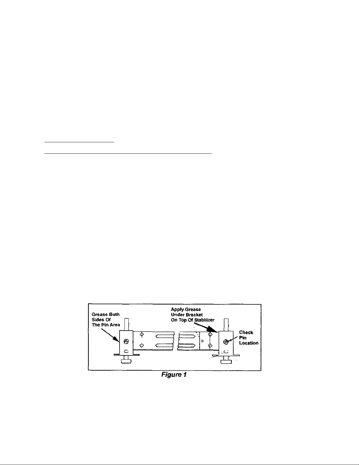
REAR LEVELING LEG SYSTEM:
Check rear leveling leg system. Verify the pins are fully inserted through the leveling legs.
Apply some lithium grease to the top of the stabilizer arm beneath the mounting bracket.
(Figure 1}
TS647 Page 2
Page 3

FRONT PANEL NOiSE:
1. Disconnect electrica! power to washer.
2. Remove the front panel of the washer.
3. Locate the package containing the two plastic
plugs in the kit. Press the plugs into the flange of
the cabinet. (Figure 2}
The plugs will bow the front panel slightly, thus
stiffening the panel and eliminating panel
vibration.
4. Locate the two "U" nut tinnermans in the kit.
5. Remove the two screws securing the "J" clips to
the baseframe. (Figure 3}
6. Position the "U" nut tinnermans onto the
baseframe over the two screw holes.
7. Remount the "J" clips to the baseframe by
screwing into the "U" nut tinnermans on the base
frame.
CABINET TO BASE NOISE:
1. Disconnect electrical power to
washer.
2. Remove the front panel of the
washer.
3. Locate the package containing the
six small foam pads in the kit.
Loosen the screws securing the
cabinet to baseframe.
4. Insert a foam pad between the
inside of the cabinet and the
baseframe and retighten the
screws securing the cabinet to
baseframe. {Figure 4)
TS647 Pages
Page 4

LOOSE CABINET NOISE
1. Disconnect electrical power to washer.
2. Remove the front panel and lift the top
cover or remove the rear access panel.
3. Locate the asphaltic pad in the kit. Clean
the surface area as indicated in Figure 5.
4. Peel the backing from the pad and posi
tion the pad onto the cabinet. Apply
pressure to the pad to firmly attach the
pad to the cabinet.
5. Lower the top cover and remount the
front panel.
CONSOLE TO TOP COVER
1. Disconnect electrical power to washer.
2. Remove the rear panel of the console.
3. Locate the two console reattachment
screws in the kit. Insert the screws
through the base of the console and into
the top cover. Fasten the screws down
into the top cover. (Figure 6)
4. Reattach rear control console panel.
TS647 Page 4
 Loading...