


Installation and Operational Instructions for
ROBA®-ES Couplings Type 940. _ _ _ . _ Sizes 14 - 65 (B.9.6.GB)
Please read the Installation and Operational Instructions carefully
and follow them accordingly.
Ignoring these instructions may lead to malfunctions or to coupling failure, resulting in damage to other parts.
Contents:
Page 1: - Contents
- Declaration of Conformity
- Safety Regulations
Page 2: - Coupling Variants
- Parts List
- Safety and Guideline Signs
- Function – Application
- State of Delivery
Page 3: - Table 1: Technical Data Type 940._22._
- Table 2: Technical Data Type 940._00._
Page 4: - Table 3: Technical Data Type 940._11.P/F
Page 5: - Table 4: Technical Data Type 940._11.A
- Table 5: Torques
Page 6: - Table 6: Permitted Misalignment Values
- Table 7: Spring Rigidities
Page 7: - Elastomeric Elements
- Elastomeric Elements - Agent Resistance
- Elastomeric Elements - Temperature Resistance
- General Installation Guidelines
- Table 8: Elastomeric Element Hardnesses and
Temperature Ranges
Declaration of Conformity
A conformity evaluation for the applicable EU directives has been carried out for this product.
The conformity evaluation is set out in writing in a separate document and can be requested if required.
It is forbidden to start use of the product until the machine or system into which it should be built is operating in accordance with all
applicable EU directives.
Without a conformity evaluation, this product is not suitable for use in areas where there is a high danger of explosion.
This statement is based on the ATEX directive.
Page 8: - Installation
- Installation of the Coupling Halves
- Installation of the Clamping Hubs
- Installation of the Key Hubs
- Installation of the Shrink Disk Hubs
- De-installation of the Shrink Disk Hubs
Page 9: - Joining Both Coupling Hubs
- Table 9: Tightening Torques & Dimension "E"
- Shaft Misalignments
- Coupling Alignment
Page 10: - Balancing the Coupling
- With Key and Clamping Hubs
- With Shrink Disk Hubs
- Diagram: Balancing the Shrink Disk Hubs
(Permitted Speeds)
- Suitable Coupling Dimensioning
Page 11: - Maintenance
- Disposal
- Malfunctions / Breakdowns
Page 12: - Malfunctions / Breakdowns
Safety Regulations
These Installation and Operational Instructions (I+O) are part of the coupling delivery.
Please keep them handy and near to the coupling at all times.
Danger!
This warning applies if:
the ROBA®-ES couplings are modified.
the relevant standards for safety and / or installation conditions are ignored.
User-implemented Protective Measures
Cover moving parts to protect against seizure, dust or foreign body impact.
To prevent injury or damage, only professionals and suitably qualified personnel should work on the devices,
following the relevant standards and directives. Please read the Installation and Operational Instructions
carefully before installing and operating the device.
These Safety Regulations are user hints only and may not be complete!
08/09/2008 TK/GH/RJ/GC Chr. Mayr GmbH + Co. KG Tel.: 08341 / 804-0
Eichenstraße 1 Fax: 08341 / 804-421
D-87665 Mauerstetten http://www.mayr.de
Page 1 of 12 Germany eMail: info@mayr.de

Installation and Operational Instructions for
3
1.123
1.1
4
1.221.2
1.2b41.2a
1.321.3
Flexible intermediate ring
ROBA®-ES Couplings Type 940. _ _ _ . _ Sizes 14 - 65 (B.9.6.GB)
Type 940._00._ Type 940._11._ Type 940._22._
ROBA®-ES with clamping hubs ROBA®-ES with shrink disk ROBA®-ES with keyway
Fig. 1 Fig. 2 Fig. 3
Parts List (Only use mayr
1.1 Clamping hub
1.2 Shrink disk hub assembly
1.2a Shrink disk
1.2b Shrink disk hub
1.3 Hub with keyway
Safety and Guideline Signs
®
original parts)
2 Elastomeric 98 Sh A (red)
Element 92 Sh A (yellow)
80 Sh A (blue)
64 Sh D (green)
3 Socket set screw
for clamping hub
4 Socket set screw
for shrink disk hub
Danger!
Danger of injury to personnel and damage
to machines.
Please Observe!
Guidelines on important points.
Please Observe!
According to German notation, decimal
points in this document are represented
with a comma (e.g. 0,5 instead of 0.5).
Function – Application
ROBA®-ES stands for:
flexible (E), backlash-free (S) shaft coupling.
It consists of two coupling hubs and a flexible, star-shaped
intermediate ring (elastomeric element) Figs. 1 – 4.
ROBA®-ES couplings are specially designed for backlash-free
operation at comparatively high speeds.
ROBA®-ES couplings are mainly used in measurement and
regulation technology as well as in control and process
technology.
ROBA®-ES couplings are shaft-shaft connections for flexible
backlash-free torque transmission in high dynamic servo drives.
08/09/2008 TK/GH/RJ/GC Chr. Mayr GmbH + Co. KG Tel.: 08341 / 804-0
Eichenstraße 1 Fax: 08341 / 804-421
D-87665 Mauerstetten http://www.mayr.de
Page 2 of 12 Germany eMail: info@mayr.de
State of Delivery
ROBA®-ES couplings are delivered manufacturer-assembled
(Please check state of delivery).
Depending on size or Type, ROBA®-ES coupling hubs are made
of aluminium or steel.
The flexible, star-shaped intermediate ring (elastomeric element)
is pressed into specially designed jaws (Fig. 5) under light pretension.
Coupling hub
Fig. 4
Fig. 5

Installation and Operational Instructions for
ROBA®-ES Couplings Type 940. _ _ _ . _ Sizes 14 - 65 (B.9.6.GB)
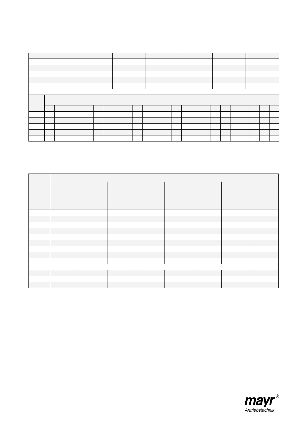
Table 1: Technical Data for Type 940._22._ (Fig. 3)
Size 14 19 24 28 38 42 48 55 65
Min. bore [mm]
Max. bore [mm]
Max. speed [rpm]
Adjusting screw thread (see Fig. 10)
Adjusting screw tightening torques [Nm]
Table 2: Technical Data for Type 940._00._ (Fig. 1)
Size 14 19 24 28 38 42 48 55 65
Min. Bore [mm]
Max. Bore [mm]
Max. speed [rpm]
Socket set screw thread
Socket set screw tightening torques [Nm]
Preferred bores on clamping hubs and respective transmittable torques [Nm]
Ø 6 Ø 7 Ø 8 Ø 9 Ø 10 Ø 11 Ø 12 Ø 14 Ø 15 Ø 16 Ø 19 Ø 20 Ø 22 Ø 24 Ø 25 Ø 28 Ø 30 Ø 32 Ø 35
Size
14
2,5 3,0 3,4 3,8 4,2 4,7 5,1 6,0 6,4 - - - - - - - - - -
19
24
28
38
42
48
55
65
Size Ø 38 Ø 40 Ø 42 Ø 45 Ø 48 Ø 50 Ø 52 Ø 55 Ø 58 Ø 60 Ø 62 Ø 65 Ø 68 Ø 70 Ø 72 Ø 75 Ø 78 Ø 80
14
19
24
28
38
42
48
55
65
- - - - 23 25 27 32 34 36 43 45 - - - - - - -
- - - - - - - - 34 36 43 45 50 54 57 63 - - -
- - - - - - - - - - 79 83 91 100 104 116 124 133 145
- - - - - - - - - - - 83 91 100 104 116 124 133 145
- - - - - - - - - - - - - - - 208 228 248 280
- - - - - - - - - - - - - - - - - - 350
- - - - - - - - - - - - - - - - - - -
- - - - - - - - - - - - - - - - - - -
- - - - - - - - - - - - - - - - - -
- - - - - - - - - - - - - - - - - -
- - - - - - - - - - - - - - - - - -
- - - - - - - - - - - - - - - - - 158 166 174 187 - - - - - - - - - - - - - 315 340 365 404 442 470 - - - - - - - - - - - 390 420 455 505 560 600 640 705 - - - - - - - - - -
- 340 365 405 435 465 490 525 570 600 625 665 700 740 - - - -
- - - 545 590 630 662 710 764 800 840 900 954 990 1032 1095 1158 1200
6 6 8 10 12 14 20 20 38
15 24 28 38 45 55 60 70 80
19000 14000 10600 8500 7100 6000 5600 5000 4600
M4 M5 M5 M6 M8 M8 M8 M10 M10
1,5 2 2 4,1 8,5 8,5 8,5 20 20
6 10 15 19 20 28 35 40 45
15 20 28 35 45 50 55 70 80
19000 14000 10600 8500 7100 6000 5600 5000 4600
M3 M6 M6 M8 M8 M10 M12 M12 M14
1,4 10 10 25 25 70 120 120 200
on clamping hubs frictional locking with shaft tolerance k6
08/09/2008 TK/GH/RJ/GC Chr. Mayr GmbH + Co. KG Tel.: 08341 / 804-0
Eichenstraße 1 Fax: 08341 / 804-421
D-87665 Mauerstetten http://www.mayr.de
Page 3 of 12 Germany eMail: info@mayr.de

Installation and Operational Instructions for
ROBA®-ES Couplings Type 940. _ _ _ . _ Sizes 14 - 65 (B.9.6.GB)
Table 3: Technical Data for Types 940._11.P and 940._11.F (Fig. 2) – Steel design
Size 14-32 19-37.5 19 24-50 24 28 38 42 48 55 65
Min. bore [mm]
Max. bore [mm]
Bore
acc. DIN 69002 [mm]
Max. speed [rpm]
6 10 10 15 15 19 20 28 35 40 45
14 16 20 24 28 38 45 50 60 70 75
14 16 19 24 25 35 - - - - -
28000 21000 21000 15500 15500 13200 10500 9000 8000 6300 5600
Clamping screw thread
Clamping screw
tightening torques [Nm]
Size
14-32
19-37,5
19
24-50
24
28
38
42
48
55
65
Size Ø 32 Ø 35 Ø 38 Ø 40 Ø 42 Ø 45 Ø 48 Ø 50 Ø 52 Ø 55 Ø 58 Ø 60 Ø 62 Ø 65 Ø 68 Ø 70 Ø 72 Ø 75
14-32
19-37,5
19
24-50
24
28
38
42
48
55
65
Ø 6 Ø 7 Ø 8 Ø 9 Ø 10 Ø 11 Ø 14 Ø 15 Ø 16 Ø 17 Ø 18 Ø 19 Ø 20 Ø 22 Ø 24 Ø 25 Ø 28 Ø 30
7 9 11 13 15 17 25 - - - - - - - - - - -
- - - - 26 30 45 50 60 - - - - - - - - -
- - - - 33 38 55 61 67 73 78 84 88 - - - - -
- - - - - - - 45 50 54 60 65 70 85 112 - - -
- - - - - - - 56 62 68 74 81 87 100 120 125 135 -
- - - - - - - - - - - 141 153 177 203 216 256 282
- - - - - - - - - - - - 197 228 261 279 332 368
- - - - - - - - - - - - - - - - 300 350
- - - - - - - - - - - - - - - - - -
- - - - - - - - - - - - - - - - -
- - - - - - - - - - - - - - - - - -
- - - - - - - - - - - - - - - - - -
- - - - - - - - - - - - - - - - - -
- - - - - - - - - - - - - - - - - -
- - - - - - - - - - - - - - - - - -
- - - - - - - - - - - - - - - - - 308 343 373 - - - - - - - - - - - - - - 405 460 513 547 577 617 - - - - - - - - - - - 400 500 600 680 730 790 850 880 - - - - - - - - - -
- 450 500 600 720 850 1000 1180 1270 1353 1428 1471 - - - - - -
- - - 723 814 946 1085 1187 1284 1436 1585 1682 1795 1943 2100 2207 - -
- - - - - 1402 1596 1731 1873 2095 2308 2420 2570 2750 2989 3157 3306 3550
4 x M3 6 x M4 6 x M4 4 x M5 4 x M5 8 x M5 8 x M6 4 x M8 4 x M8 4 x M10 4 x M12
1,3 3,0 3,0 6,0 6,0 6,0 10 25 30 52 90
Preferred bores on clamping hubs and respective transmittable torques [Nm]
on clamping hubs frictional locking with shaft tolerance k6
08/09/2008 TK/GH/RJ/GC Chr. Mayr GmbH + Co. KG Tel.: 08341 / 804-0
Eichenstraße 1 Fax: 08341 / 804-421
D-87665 Mauerstetten http://www.mayr.de
Page 4 of 12 Germany eMail: info@mayr.de
Installation and Operational Instructions for
ROBA®-ES Couplings Type 940. _ _ _ . _ Sizes 14 - 65 (B.9.6.GB)
Table 4: Technical Data for Type 940._11.A (Fig. 2) – Aluminium design
Size
Min. bore [mm]
Max. bore [mm]
Max. speed [rpm]
Clamping screw thread
Clamping screw tightening torques [Nm]
Preferred bores on clamping hubs and respective transmittable torques [Nm]
Ø 6 Ø 7 Ø 8 Ø 9 Ø 10 Ø 11 Ø 14 Ø 15 Ø 16 Ø 17 Ø 18 Ø 19 Ø 20 Ø 22 Ø 24 Ø 25 Ø 28 Ø 30 Ø 32 Ø 35 Ø 38 Ø 40 Ø 42 Ø 45
Size
14
7 9 11 13 15 17 24 - - - - - - - - - - - - - - -
19
- - - - 33 38 55 61 67 73 78 84 88 - - - - - - - - - - -
24
- - - - - - - 56 62 68 74 81 87 100 120 125 135 - - - - - - -
28
- - - - - - - - - - - 141 153 177 203 216 256 282 308 343 373 - - -
38
- - - - - - - - - - - - 197 228 261 279 332 368 405 460 513 547 577 617
on clamping hubs frictional locking with shaft tolerance k6
14 19 24 28 38
6 10 15 19 20
14 20 28 38 45
28000 21000 15500 13200 10500
4 x M3 6 x M4 4 x M5 8 x M5 8 x M6
1,3 3,0 6,0 6,0 10
Table 5: Torques
This concerns measurement torques. For exact dimensioning, please observe the transmittable torques of the respective shafthub connections as well as the design calculation for the most recent ROBA®-ES catalogue.
Torque Type 940._ _ _._
Elastomeric element
hardness
80 Sh A (blue)
Size
14
19
24
28
38
42
48
55
65
Only available as Type 940._11.P
14-32
19-37,5
24-50
TKN
[Nm]
4 8 8 16 13 26 16 32
5 10 10 20 17 34 21 42
17 34 35 70 60 120 75 150
46 92 95 190 160 320 200 400
- - 190 380 325 650 405 810
- - 265 530 450 900 560 1120
- - 310 620 525 1050 655 1310
- - 410 820 685 1370 825 1650
- - 900 1800 1040 2080 - -
4 8 8 16 13 26 16 32
4 8 8 16 14 28 17 34
12 24 25 50 43 86 54 108
T
K max
[Nm]
Elastomeric element
hardness
92 Sh A (yellow)
TKN
[Nm]
T
K max
[Nm]
Elastomeric element
hardness
98 Sh A (red)
TKN
[Nm]
T
K max
[Nm]
Elastomeric element
hardness
64 Sh D (green)
TKN
[Nm]
T
K max
[Nm]
08/09/2008 TK/GH/RJ/GC Chr. Mayr GmbH + Co. KG Tel.: 08341 / 804-0
Eichenstraße 1 Fax: 08341 / 804-421
D-87665 Mauerstetten http://www.mayr.de
Page 5 of 12 Germany eMail: info@mayr.de

Installation and Operational Instructions for
Available on demand
Available on demand
Available on demand
ROBA®-ES Couplings Type 940. _ _ _ . _ Sizes 14 - 65 (B.9.6.GB)
Table 6: Permitted Misalignment Values
Shaft misalignments
Axial Radial Angular
∆Ka
80/92/98 Sh A
64 Sh D
Size
14
19
24
28
38
42
48
55
65
[mm]
1,0 0,21 0,15 0,09 0,06 1,1 1,0 0,9 0,8
1,2 0,15 0,10 0,06 0,04 1,1 1,0 0,9 0,8
1,4 0,18 0,14 0,10 0,07 1,1 1,0 0,9 0,8
1,5 0,20 0,15 0,11 0,08 1,3 1,0 0,9 0,8
1,8 - 0,17 0,12 0,09 - 1,0 0,9 0,8
2,0 - 0,19 0,14 0,10 - 1,0 0,9 0,8
2,1 - 0,21 0,16 0,11 - 1,0 0,9 0,8
2,2 - 0,24 0,17 0,12 - 1,0 0,9 0,8
2,6 - 0,25 0,18 - - 1,0 0,9 -
Only available as Type 940._11.P
14-32
19-37,5
24-50
1,0 0,21 0,15 0,09 0,06 1,1 1,0 0,9 0,8
1,2 0,15 0,10 0,06 0,04 1,1 1,0 0,9 0,8
1,4 0,18 0,14 0,10 0,07 1,1 1,0 0,9 0,8
Table 7: Spring Rigidities
∆Kr
80 Sh A
[mm]
∆Kr
92 Sh A
[mm]
∆Kr
98 Sh A
[mm]
∆Kr
64 Sh D
[mm]
∆Kw
80 Sh A
[°]
∆Kw
92 Sh A
[°]
∆Kw
98 Sh A
[°]
∆Kw
64 Sh D
[°]
Static Torsional Spring Rigidity Dynamic Torsional Spring Rigidity Static Radial Torsional Spring Rigidity
Size
14
19
24
28
38
42
48
55
65
C
T stat.
80 Sh A
[Nm/rad.]
50 80 120 230 120 240 300 730 180 300 470 960
350 820 900 1400 1050 1800 2200 4200 700 1200 2100 2700
820 2300 3700 4500 1300 4800 7600 10800 800 1900 2800 4200
1300 3800 4200 7000 2200 6800 10100 17200 950 2100 3500 4900
C
T stat.
92 Sh A
[Nm/rad.]
- 5600 7400 9000 - 11900 19900 30500 - 2900 4800 5600
- 9800 13800 15000 - 20500 31100 64900 - 4100 5400 6900
- 12000 15100 28500 - 22800 44900 102800 - 4500 6200 8200
- Available on demand - Available on demand - Available on demand
-
Only available as Type 940._11.P
14-32
19-37,5
24-50
50 80 120 230 120 240 300 730 180 300 470 960
280 660 720 1120 840 1440 1760 3360 560 960 1680 2160
600 1700 2700 3300 1000 3600 5700 8100 600 1500 2100 3200
C
T stat.
98 Sh A
[Nm/rad.]
C
T stat.
64 Sh D
[Nm/rad.]
- -
C
T dyn.
80 Sh A
[Nm/rad.]
C
T dyn.
92 Sh A
[Nm/rad.]
C
T dyn.
98 Sh A
[Nm/rad.]
C
T dyn.
64 Sh D
[Nm/rad.]
- -
C
r
80 Sh A
[Nm/mm]
C
r
92 Sh A
[Nm/mm]
C
r
98 Sh A
[Nm/mm]
C
r
64 Sh D
[Nm/mm]
-
08/09/2008 TK/GH/RJ/GC Chr. Mayr GmbH + Co. KG Tel.: 08341 / 804-0
Eichenstraße 1 Fax: 08341 / 804-421
D-87665 Mauerstetten http://www.mayr.de
Page 6 of 12 Germany eMail: info@mayr.de

Installation and Operational Instructions for
ROBA®-ES Couplings Type 940. _ _ _ . _ Sizes 14 - 65 (B.9.6.GB)
Elastomeric Elements (2)
The elastomeric elements (2) are the central element of the
ROBA®-ES coupling. They define the area of application via the
permitted torque, rigidity, damping and misalignment values and
the performance of the shaft connection.
By using a new polyurethane material and a special injection
method, a high degree of dimensional stability and uniformity in
the toothing of the elastomeric element (2) is achieved. The
elastomeric elements are available in different shore hardnesses
(see Table 8).
The teeth on the elastomeric element (2) are chamfered laterally,
which eases blind installation.
Elastomeric Elements - Agent Resistance (2)
The elastomeric elements (2) are very resistant against
pure mineral oils (lubricating oils)
waterproof greases.
They have similar resistance against fuels such as
standard petrol
diesel
kerosene.
Damage can occur due to longer influence of
alcohols
aromatic fuels (super petrol).
The elastomeric element material used is resistant to hydrolysis.
In contrast to other polyurethane materials, water (also sea
water) does not cause any substantial changes in the
mechanical characteristics even after many years of contact.
However, hot water reduces the mechanical rigidity.
Please contact the manufacturer in case of contact with special
agents or radiation.
Elastomeric Elements (2) - Temperature
Resistance
The ambient temperatures present during operation have a
considerable effect on the torque, the rigidity or the damping
behaviour of the coupling. The permitted temperature ranges
(according to Table 8) are to be kept to.
General Installation Guidelines
The bores of the coupling hubs have an H7 tolerance in shrink
disk and keyway designs or an F7 tolerance in clamping hub
design in standard production. We recommend a k6 tolerance*
for the shafts. The surface of the shafts should be finely turned
or ground (Ra = 0,8 µm).
In case of customer-side bores, please observe the shaft run-out
tolerance 0,05 to "A" (see Fig. 6).
The bores or shafts must not be oiled or greased when
installing the coupling with clamping hubs (1.1) or shrink disk
hubs (1.2).
(* Please contact the manufacturer for other shaft tolerances.)
Fig. 6 ROBA
with keyway
Fig. 7 ROBA
Table 8: Elastomeric Element Hardnesses and Permitted Temperature Ranges
®
-ES
®
with shrink disk hubs
-ES
hardness
[Shore]
80 Sh A Blue -50 up to +80 °C -60 up to +120 °C
92 Sh A Yellow -40 up to +90 °C -50 up to +120 °C
98 Sh A Red -30 up to +90 °C -40 up to +120 °C
64 Sh D Green -30 up to +100 °C -40 up to +140 °C
08/09/2008 TK/GH/RJ/GC Chr. Mayr GmbH + Co. KG Tel.: 08341 / 804-0
Eichenstraße 1 Fax: 08341 / 804-421
D-87665 Mauerstetten http://www.mayr.de
Page 7 of 12 Germany eMail: info@mayr.de
Colour
Permanent temperature Max. temporary temperature
Permitted temperature range Elastomeric element

Installation and Operational Instructions for
3
1.123
1.1
4
1.221.2
1.2b
4
1.2a
1.321.3
Adjusting screw threaded hole
ROBA®-ES Couplings Type 940. _ _ _ . _ Sizes 14 - 65 (B.9.6.GB)
Installation
Due to their optimised construction, the ROBA®-ES coupling
provides customers with the possibility of attaching the coupling
axially after the hubs have been installed on the input or output
shafts.
Subsequent screwing procedures and complex housing
constructions become unnecessary..
(see Installation Examples Figs. 6, 7 and 11).
Please Observe!
ROBA®-ES couplings with steel hubs and
steel shrink disks are coated with a zinc
phosphation, which provides corrosion
protection. All other components are
untreated.
For both steel and aluminium hubs, the
bores or shafts have to be degreased
before installing the coupling Types:
with clamping hubs 940._00._
with shrink disk hubs 940._11._.
Greasy or oily bores or shafts do not
transmit the indicated transmittable
torque TR specified on order.
Installation of the Coupling Halves (Hubs)
Installation of the Coupling Clamping Hubs
Type 940._00._ (Fig. 8)
Push the coupling hubs (1.1) using a suitable device onto
both shaft ends, and bring them into the correct position.
Tighten the clamping screw (3) using a torque wrench
evenly to the required torque acc. Table 2.
Fig. 8
Installation of the Coupling Hubs with Keyway
Type 940._22._ (Fig. 10)
In order to dimension the shaft-hub connection or to inspect the
permitted contact pressure per unit area of the keyway, the
calculation procedure acc. DIN 6892 usual in mechanical
engineering is to be applied.
For calculation, please take the yield point as Rp 0,2 for
aluminium 200 N/mm2 and for steel 350 N/mm2.
Push the coupling hubs (1.3) using a suitable device onto
both shaft ends and bring them into the correct position.
Secure the hubs (1.3) axially (see also Installation Example
Fig. 6).
Axial securement takes place via a set screw (adjusting
screw / Fig. 10).
The key must lie over the entire length of the hub.
Installation of the Coupling Shrink Disk Hubs
Type 940._11._ (Fig. 9)
The contact surfaces of the cone shrink disk (1.2b) or cone
shrink disk hub (1.2a) are greased manufacturer-side.
Push the coupling hubs (1.2) using a suitable device onto
both shaft ends and bring them into the correct position.
Tighten the clamping screws (4) until they are lying lightly up
against their receptor part.
Tighten the clamping screws stepwise and crosswise (in 3
to max. 6 tightening turns) evenly using a torque wrench to
the required tightening torque according to Tables 3 or 4
(dependent on Type).
Fig. 9
De-installation
Loosen all clamping screws (4) by several tightening turns.
Screw out the clamping screws next to the tapped extracting
holes, and screw them into the tapped extracting holes up to
their limits.
Tighten the clamping screws (4) stepwise evenly. In this
way, the clamping ring (1.2b) is forced away from the shrink
disk hub (1.2a) (Fig. 9).
Fig. 10
08/09/2008 TK/GH/RJ/GC Chr. Mayr GmbH + Co. KG Tel.: 08341 / 804-0
Eichenstraße 1 Fax: 08341 / 804-421
D-87665 Mauerstetten http://www.mayr.de
Page 8 of 12 Germany eMail: info@mayr.de

Installation and Operational Instructions for
∆
K
r
∆
K
a
∆
K
w
100
Angular misalignment
K [%] Axial displace
a
∆
m
i
s
a
l
i
g
n
m
e
n
t
K
[
%
]
R
a
d
i
a
l
ROBA®-ES Couplings Type 940. _ _ _ . _ Sizes 14 - 65 (B.9.6.GB)
Joining Both Coupling Hubs
Due to the pre-tension on the flexible elastomeric element (2), an
axial installation force must be produced (Fig. 5) when the
coupling hubs are joined (1.1-1.3).
The force required can be reduced by lightly greasing the
elastomeric element.
Right hub showed
mirrored
Fig. 11 ROBA
Please Observe!
Use PU-compatible lubricants
(e. g. Vaseline or HP 222)!
Please Observe!
After joining both coupling parts, no axial
pressure must be placed on the elastomeric
element (2).
Keep to distance dimension "E" acc. Fig. 11
and Table 9!
E
®
-ES with clamping hub
Table 9:
Tightening Torques und Distance Dimension "E"
Tightening torques
ROBA®-ES
Size
14
19
24
28
38
42
48
55
65
socket set
screws
(Item 3,
Fig. 1)
[Nm]
1,4 1,3 13
10 3 16
10 6 18
25 6 20
25 10 24
70 25 26
120 30 28
120 52 30
200 90 35
clamping
screws
(Item 4,
Fig. 2)
[Nm]
Distance
dimension
"E"
(Fig. 11)
[mm]
Shaft Misalignments
ROBA®-ES couplings are capable of compensating for radial,
axial and angular shaft misalignments (Fig. 13), without losing
their resistance to backlash.
However, the permitted shaft misalignments shown in Table 6
may not simultaneously reach their maximum value. If more than
one kind of misalignment takes place simultaneously, they
influence each other. Therefore, each permitted alignment value
(see Fig. 12) is dependent on another. The sum total of the
actual misalignments in percent of the maximum value must not
exceed 100 %.
The permitted shaft misalignments shown in Table 6 refer to
coupling operation at nominal torque, an ambient temperature of
+30 °C and an operating speed of 1500 rpm. In other or more
extreme coupling conditions, please contact the manufacturers.
100
80
60
40
30
r
20
0
0
50
75%
20
∆ ment
%
25%
40
∆ K
0
%
30
w
%
60
[%]
80
Fig. 12
Coupling Alignment
An exact coupling alignment greatly increases the lifetime of the
clutch and reduces the load on the shaft bearings.
In particularly high speed drives, we recommend the use of an
alignment device (e.g. laser).
Normally however, it is sufficient to align the coupling using a
straight edge at two vertical levels next to each other.
L
Fig. 13 Radial misalignment Axial displacement Angular misalignment
08/09/2008 TK/GH/RJ/GC Chr. Mayr GmbH + Co. KG Tel.: 08341 / 804-0
Eichenstraße 1 Fax: 08341 / 804-421
D-87665 Mauerstetten http://www.mayr.de
Page 9 of 12 Germany eMail: info@mayr.de

Installation and Operational Instructions for
30.000
n
G
n
max
e
d
Size
S
p
e
e
d
[
r
p
m
]
ROBA®-ES Couplings Type 940. _ _ _ . _ Sizes 14 - 65 (B.9.6.GB)
Balancing
Key hubs (1.3) and clamping hubs (1.1):
The key hubs (1.3) and clamping hubs (1.1) rotate at maximum
speed with a circumferential speed of 30 m/s.
They are not balanced in the standard process.
Shrink disk hub(1.2):
The shrink disk hubs (steel and aluminium) (1.2) maintain a
balance quality of G = 6,3 without being balanced up to speed n
(equals c. 30 m/s). Over this speed, balancing is recommended.
The hubs are balanced individually. The diagram (Fig. 14) gives
reference values for balancing the coupling, which we
recommended you use.
The running smoothness of a machine or system is not
dependent on the balance quality of the coupling, but rather on
many parameters such as rigidity or distance to the adjoining
bearing. For this reason there are no fixed regulations as to the
conditions for which a coupling should be balanced.
25.000
20.000
15.000
10.000
5.000
0
14 19 24 28 38 42 48 55 65
B
a
l
a
n
c
i
n
g
r
e
c
o
m
m
e
n
d
Fig. 14 Diagram: Balancing the Shrink Disk Hubs
G
Suitable Coupling Dimensioning
For malfunction-free function of the coupling, please keep to the
given coupling characteristic values (Technical Data) in the most
recent applicable catalogue. Suitable coupling dimensioning
according to the applicable ROBA®-ES catalogue is necessary for
malfunction-free and wear-free operation.
Large shaft misalignments, in particular with high speeds and an
alternating overall load configuration with high frequency, strain
and heat up the elastomer material.
Unpermittedly high load configuration, unpermittedly high speeds
and unpermitted shaft misalignments can destroy the coupling.
For suitable coupling dimensioning (see calculation in the most
recent applicable ROBA®-ES catalogue), please observe the
following points:
a.) Coupling nominal torque
b.) Coupling peak transient torque
c.) Max. speed
d.) Max. shaft misalignments
e.) Ambient conditions (see most recent applicable
ROBA®-ES catalogue)
f.) Service factors (see most recent applicable
ROBA®-ES catalogue)
The number and type of start-up impacts must be taken into
account according to the catalogue during coupling dimensioning.
Furthermore, elastomer heating may occur due to speed
resonance. This must also be taken into account according to the
catalogue during coupling dimensioning. Changed operating
parameters in the system require a renewed inspection of the
coupling dimensioning. The maximum given ambient
temperatures are to be kept to. Exceeding the permitted ambient
temperatures means a danger of elastomer destruction.
Danger!
Any operation outside the given
characteristic data is not allowed. Danger of
coupling destruction.
08/09/2008 TK/GH/RJ/GC Chr. Mayr GmbH + Co. KG Tel.: 08341 / 804-0
Eichenstraße 1 Fax: 08341 / 804-421
D-87665 Mauerstetten http://www.mayr.de
Page 10 of 12 Germany eMail: info@mayr.de

Installation and Operational Instructions for
Dismantle the coupling and remove the remains of the elastomeric
Elastomeric
Feeler gauge 0,1 mm
ROBA®-ES Couplings Type 940. _ _ _ . _ Sizes 14 - 65 (B.9.6.GB)
Maintenance
Please keep to the following maintenance and inspection
intervals:
1.) Visual check, inspection of the installation
parameters (misalignment and tightening torques),
running behaviour of the coupling before initial
operation.
2.) Visual check, torsional backlash and elastomer wear,
inspections of misalignment and tightening torques,
running behaviour of the coupling after 1000h or
after max. 3 months.
3.) If no irregularities or wear are found during the
second maintenance and inspection interval, all
further inspection intervals can be carried out under
unchanged operating parameters after 4000
operating hours or after max. 12 months.
Elastomer wear limit :
No abraded particles are allowed on the Elastomeric element (2),
as the ROBA®-ES is a backlash-free coupling. The gap between
two jaws must be filled with the elastomer, with no room for
backlash.
You should not be able to insert a feeler gauge with a thickness of
0,1 mm (Fig. 15).
Hub 1
Hub 2
element
Fig. 15
Malfunctions / Breakdowns
If wear or damage is discovered, the affected parts must be
replaced immediately and the cause of the malfunction is to be
found.
Malfunction causes could be:
a.) Excessive misalignment
b.) Excessive load
(alternating loads, start-up impacts, overload)
c.) Ambient influences
Wear or damage on the ROBA®-ES coupling becomes apparent
by:
a.) Noise development
b.) Disturbed running, vibrations
c.) Crack formation on the components
d.) Heating
e.) Loosened components
f.) Friction marks
Danger!
For any irregularities, independent of the
regular maintenance and inspection
intervals, the system is to be stopped and
the cause of malfunction is to be found
using the Table Malfunctions / Breakdowns
Disposal
All steel components:
Steel scrap (Code No. 160117)
All aluminium components:
Non-ferrous metals (Code No. 160118)
Elastomere:
Plastics (Code No. 160119)
Malfunctions Possible causes
1) Set the system out of operation
2) Find and solve the cause of incorrect alignment
Incorrect alignment
Changes in running
noise and / or
vibration occurrence
08/09/2008 TK/GH/RJ/GC Chr. Mayr GmbH + Co. KG Tel.: 08341 / 804-0
Eichenstraße 1 Fax: 08341 / 804-421
D-87665 Mauerstetten http://www.mayr.de
Page 11 of 12 Germany eMail: info@mayr.de
Wear on the elastomeric element,
temporary torque transmission due
to metal contact
Loose clamping screws and socket
set screws or locking set screw for
axial hub securement
(e. g. loose foundation screws, motor securement breakage, warmth
expansion of system components, changes in the coupling
installation dimension "E")
3) Check the coupling for wear
1) Set system out of operation
2)
element
3) Check the coupling parts and replace them if damaged
4) Insert a new elastomeric element, install coupling parts
5) Check the alignment and correct if necessary
1) Set system out of operation
2) Check the coupling alignment
3) Tighten the clamping and socket set screws for axial securement of
the hubs to the specified torque, or tighten the locking set screw and
paint it with thread locking solution against self-loosening
4) Check the coupling for wear
Solution

Installation and Operational Instructions for
lead to physical changes in the
Dismantle the coupling and remove the remains of the elastomeric
Dismantle the coupling and remove the remains of the elastomeric
Dismantle the coupling and remove the remains of the elastomeric
ROBA®-ES Couplings Type 940. _ _ _ . _ Sizes 14 - 65 (B.9.6.GB)
Malfunctions / Breakdowns
Malfunctions Possible causes
Wear on the elastomeric element,
Cam breakage
Premature wear on
the elastomeric
element
torque transmission due to metal
Cam breakage due to high impact
energy / overload / excessively high
Operating parameters do not match
the coupling performance
Operational mistakes due to
coupling characteristic data being
contact
shaft misalignments
exceeded
Incorrect alignment
Solutions
1) Set system out of operation
2) Replace the entire coupling
3) Check the alignment
1) Set system out of operation
2) Replace the entire coupling
3) Check the alignment
4) Find the cause of overload
1) Set system out of operation
2) Check the operating parameters and select a suitable coupling
(please observe the installation space)
3) Install a new coupling
4) Check the alignment
1) Set system out of operation
2) Check coupling dimensioning
3) Replace the entire coupling
4) Check the alignment
5) Train operating personnel
1) Set system out of operation
2) Find and solve the cause of incorrect alignment
(e. g. loose foundation screws, motor securement breakage, warmth
expansion of system components, changes in the coupling
installation dimension "E")
3) Check the coupling for wear
Premature wear on
the elastomeric
element
Premature wear on
the elastomeric
element (material
liquidation inside the
elastomeric element
toothing)
1) Set system out of operation
e.g. Contact with aggressive liquids /
oils, ozone influences, excessively
high ambient temperature etc., which
elastomeric element
The ambient or contact
temperatures permitted for the
elastomeric element are exceeded
(see Table 8)
Drive vibrations
Please Observe!
mayr ® will take no responsibility or guarantee for replacement parts and accessories which have not been delivered by
mayr ®, or for damage resulting from the use of these products.
2)
element
3) Check the coupling parts and replace them if damaged
4) Insert a new elastomeric element, install coupling components
5) Check the alignment and correct if necessary
6) Make sure that further physical changes to the elastomeric element
can be ruled out.
1) Set system out of operation
2)
element
3) Check the coupling parts and replace them if damaged
4) Insert a new elastomeric element, install coupling components
5) Check the alignment and correct if necessary
6) Check the ambient or contact temperature and regulate them (if
necessary, use other elastomeric element materials)
1) Set system out of operation
2)
element
3) Check the coupling parts and replace them if damaged
4) Insert a new elastomeric element, install the coupling components
5) Check the alignment and correct if necessary
6) Find the cause of vibration (if necessary, use an elastomeric
element with a lower or higher shore hardness)
08/09/2008 TK/GH/RJ/GC Chr. Mayr GmbH + Co. KG Tel.: 08341 / 804-0
Eichenstraße 1 Fax: 08341 / 804-421
D-87665 Mauerstetten http://www.mayr.de
Page 12 of 12 Germany eMail: info@mayr.de
 Loading...