

Installation and Operational Instructions for
CAUTION
Danger of injury to personnel and
damage to machines.
Please Observe!
Guidelines on important points.
Safety Regulations
These Installation and Operational Instructions (I + O) are part of the clutch delivery.
Please keep them handy and near to the clutch at all times.
It is forbidden to start use of the product until you have ensured that all applicable EU directives and directives for the
machine or system into which the product has been installed have been fulfilled.
At the time these Installation and Operational Instructions go to print, the EAS®-smartic® clutches accord with the known
technical specifications and are operationally safe at the time of delivery.
Without a conformity evaluation, this product is not suitable for use in areas where there is a high danger of explosion.
This statement is based on the ATEX directive.
CAUTION
If the EAS®-smartic® clutches are modified.
If the relevant standards for safety and / or installation conditions are ignored.
User-implemented Protective Measures
Cover all moving parts to protect against seizure, dust or foreign body impact.
The clutch may not be put into operation without a limit switch unless mayr ® has been contacted and has agreed
otherwise.
To prevent injury or damage, only professionals and specialists should work on the devices, following the
relevant standards and directives. Please read the Installation and Operational Instructions carefully before
installation and initial operation of the device.
These Safety Regulations are user hints only and may not be complete!
EAS®-smartic
®
synchronous clutch Type 48_._ _5._
Sizes 01 – 2 (B.4.17.1.GB)
Please read these Operational Instructions carefully and follow them accordingly!
Ignoring these Instructions may lead to malfunctions or to clutch failure, resulting in damage to other parts.
Contents:
Page 1: - Contents
- Safety and Guideline Signs
- Safety Regulations
Page 2: - Illustrations Type 481._ _5._
- Illustrations Type 484._ _5._
Page 3: - Illustrations Type 486._ _5._
Page 4: - Parts List
Page 5: - Table 1: Technical Data
Page 6: - Table 2: Screws Overview
Page 7: - Design
- State of Delivery
- Function
- Installation of the Output Elements
Page 8: - Mounting onto the Shaft on Type 481
Page 9: - Mounting onto the Shaft on Type 484
Page 10: - Mounting onto the Shaft on Type 486
Page 11: - Permitted Shaft Misalignments
- Shaft Alignment
Page 12: - Torque Adjustment
- Cup Spring Layering
- Changing the Torque
- Table 3: Cup Spring Layering and
Torque Ranges
Page 13: - Changing the Torque Adjustment Range
by Changing the Cup Spring Layering
Page 14: - Limit Switch Installation
- Maintenance
- Disposal
Page 15: - General Malfunctions / Breakdowns
Page 16: - Malfunctions / Breakdowns Type 484.
Page 17: - Malfunctions / Breakdowns Type 484.
Page 18: - Malfunctions / Breakdowns Type 486.
Safety and Guideline Signs
25/11/2011 TK/NU/SU Chr. Mayr GmbH + Co. KG Tel.: +49 8341 804-0
Eichenstraße 1 Fax: +49 8341 804-421
D-87665 Mauerstetten http://www.mayr.com
Page 1 of 18 Germany E-Mail: info@mayr.de

Installation and Operational Instructions for
15 14 13
17
16/16.1
23
24
Item 18 (contactless limit switch)
8 87 73 39 912 1210 105
22
21
20
1.2
19
6
1/1.1
2
11
11
44 4 Item 18
EAS®-smartic
®
synchronous clutch Type 48_._ _5._
Sizes 01 – 2 (B.4.17.1.GB)
Type 481._ _ _._
Clamping ring hub with and without keyway Hub key design
Fig. 1
Type 484._ _ _._
Clamping hub Clamping ring hub
with and without with and without
keyway keyway
Hub Hub
key key
design design
Fig. 2
25/11/2011 TK/NU/SU Chr. Mayr GmbH + Co. KG Tel.: +49 8341 804-0
Eichenstraße 1 Fax: +49 8341 804-421
D-87665 Mauerstetten http://www.mayr.com
Page 2 of 18 Germany E-Mail: info@mayr.de

28
27
27
27
37
31
30
30
30
29
31
26
263825
30 3827
38
25
32/32.1
35
33
33
34
36/36.1
29
29
40
29
39
Installation and Operational Instructions for
EAS®-smartic
®
synchronous clutch Type 48_._ _5._
Sizes 01 – 2 (B.4.17.1.GB)
Type 486._ _ _._
Clamping hub
with and without
keyway Single-jointed
Size 2 design
Hub
key
design
Size 2
Clamping ring hub
with and without
keyway
Hub large Double-jointed
keyway design
design
Size 2
Flange
Size 2
Single-jointed
design
Hub
key design
Clamping hub
with and without
keyway
Sizes 01 to 1
Double-jointed
design
Fig. 3
25/11/2011 TK/NU/SU Chr. Mayr GmbH + Co. KG Tel.: +49 8341 804-0
Eichenstraße 1 Fax: +49 8341 804-421
D-87665 Mauerstetten http://www.mayr.com
Page 3 of 18 Germany E-Mail: info@mayr.de

Installation and Operational Instructions for
Item
Name
Item
Name
1
Clamping ring hub
20
Adjusting nut (for key design)
1.1
Clamping ring hub with keyway
21
Locking ring (for key design)
1.2
Clamping ring
22
Hexagon head screw (for key design)
1.3
Spring pin (Fig. 15 / page 13)
23
Hub Type 484. (key design)
2
Cap screw
24
Set screw
3
Pressure flange
25
Connection flange Type 486.
4
Thrust washer
26
Cap screw
5
Adjusting nut (for clamping ring hub design)
27
Screw
6
Hexagon head screw (for clamping ring hub design)
28
Hexagon head screw
7
Deep groove ball bearing
29
Hexagon nut
8
Locking ring
30
Disk pack assembly
9
Steel ball
31
Connection plate
10
Cup spring (layering dependent on Type)
32
Clamping hub Type 486. (Size 2)
11
Adjustment Table
32.1
Clamping hub Type 486. with keyway (Size 2)
12
Type tag
33
Cap screw
13
Connection flange Type 484.
34
Hub Type 486. (key design / Size 2)
14
Cap screw
35
Set screw
15
Flexible elastomeric element
36
Clamping hub Type 486. (Sizes 01 to 1)
16
Clamping hub Type 484.
36.1
Clamping hub Type 486. with keyway (Sizes 01 to 1)
16.1
Clamping hub Type 484. with keyway
37
Cap screw
17
Cap screw
38
Screw
18
Limit switch
39
Hub, large (key design)
19
Hub (key design)
40
Flange
The limit switch Item 18 is not included in the
standard delivery.
EAS®-smartic
®
synchronous clutch Type 48_._ _5._
Sizes 01 – 2 (B.4.17.1.GB)
Parts List (Only use mayr
original parts)
25/11/2011 TK/NU/SU Chr. Mayr GmbH + Co. KG Tel.: +49 8341 804-0
Eichenstraße 1 Fax: +49 8341 804-421
D-87665 Mauerstetten http://www.mayr.com
Page 4 of 18 Germany E-Mail: info@mayr.de

Installation and Operational Instructions for
Size
01 0 1
2
Thread in the pressure flange (Item 3)
8 x M4
8 x M4
8 x M5
8 x M6
Max. screw-in depth b
max
in the pressure flange (Item 3) [mm]
6
6,5 7 9,5
Connection dimension "a" +0,1 [mm]
2,5
2,5
2,5
3
Connection dimension "e" [mm]
42 h5
52 h5
65 h5
78 h5
Tightening torque (Item 2) [Nm]
40
40
83
140
Tightening torque (Item 14) 1) [Nm]
4
4,5 9 16
Tightening torque (Item 17) [Nm]
Types 484.2_5._ to 484.7_5._
10 25 25 120
Type 484.8_5._
17
40
40
140
Tightening torque (Item 26) 1) [Nm]
4
4,5 9 16
Tightening torque (Items 27 / 28 / 38) [Nm]
8,5
8,5
8,5
8,5
Tightening torque (Item 33) [Nm]
13
33
33
42
Tightening torque (35) up to bore Ø 22 [Nm]
more than bore Ø 22 [Nm]
2
4,1
Tightening torque (37) [Nm]
8,5
8,5
8,5
-
Axial forces [N]
400
500
800
1200
Radial forces [N]
400
500
800
1200
Transverse force torques 2) [Nm]
3 5 10
15
Distance dimension "E" (see Figs. 5 and 6) [mm]
18
20
24
28
Distance dimension "U1" (see Figs. 7 and 8) [mm]
14,7
15,5
15,8
26,4
Distance dimension "S" (see Fig. 9) [mm]
2,6 3 2,9
7,2
Permitted shaft misalignments Type 484._ _ 5._
Radial misalignment ΔK
r
92 Sh A [mm]
98 Sh A [mm]
0,14
0,10
0,15
0,11
0,17
0,12
0,21
0,16
Axial displacement ΔKa [mm]
1,4
1,5
1,8
2,1
Angular misalignment ΔKw 92 Sh A [°]
98 Sh A [°]
1,0
0,9
1,0
0,9
1,0
0,9
1,0
0,9
Permitted shaft misalignments Type 486._ _ 5.0 (Double-jointed coupling)
Radial misalignment ΔKr [mm]
0,15
0,2
0,2
0,3
Axial displacement ΔKa [mm]
0,7
0,9
1,1
1,3
Angular misalignment ΔKw [°]
2,0
2,0
2,0
2,0
Permitted shaft misalignments Type 486._ _ 5.8 (Single-jointed coupling)
Radial misalignment ΔK
r
[mm]
- - -
-
Axial displacement ΔKa [mm]
0,35
0,45
0,55
0,65
Angular misalignment ΔKw [°]
1,0
1,0
1,0
1,0
EAS®-smartic
®
synchronous clutch Type 48_._ _5._
Sizes 01 – 2 (B.4.17.1.GB)
Table 1: Technical Data
1)
Secure Items 14 and 26 wit Loctite 243.
2)
Torques, which put strain on the deep groove ball bearing due to the non-centric axial forces having an effect on the pressure flange.
25/11/2011 TK/NU/SU Chr. Mayr GmbH + Co. KG Tel.: +49 8341 804-0
Eichenstraße 1 Fax: +49 8341 804-421
D-87665 Mauerstetten http://www.mayr.com
Page 5 of 18 Germany E-Mail: info@mayr.de
Installation and Operational Instructions for
Item
Design
Size 01
Size 0
Size 1
Size 2
2
with hub
Items 1 / 1.1
1x cap screw
M8 x 25
DIN EN ISO 4762
12.9
1x cap screw
M8 x 25
DIN EN ISO 4762
12.9
1x cap screw
M10 x 30
DIN EN ISO 4762
12.9
1x cap screw
M12 x 35
DIN EN ISO 4762
12.9
6
with hub
Items 1 / 1.1
1x hexagon head screw
M4 x 24,2 SO
(DIN EN ISO 4014)
8.8
1x hexagon head screw
M4 x 24,2 SO
(DIN EN ISO 4014)
8.8
1x hexagon head screw
M5 x 28 SO
(DIN EN ISO 4014)
8.8
1x hexagon head screw
M6 x 31,5 SO
(DIN EN ISO 4014)
8.8
14
Type
484._ _5._
8x cap screw
M4 x 16
DIN EN ISO 4762
12.9
8x cap screw
M4 x 16
DIN EN ISO 4762
12.9
8x cap screw
M5 x 18
DIN EN ISO 4762
12.9
8x cap screw
M6 x 22
DIN EN ISO 4762
12.9
17
with hub
Items 16 / 16.1
1x cap screw
M6 x 20
DIN EN ISO 4762
8.8
1x cap screw
M8 x 25
DIN EN ISO 4762
8.8
1x cap screw
M8 x 30
DIN EN ISO 4762
8.8
1x cap screw
M12 x 35
DIN EN ISO 4762
12.9
22
with hub
Item 19
1x hexagon head screw
M3 x 8
DIN EN ISO 4017
8.8
1x hexagon head screw
M4 x 10
DIN EN ISO 4017
8.8
1x hexagon head screw
M5 x 10
DIN EN ISO 4017
8.8
1x hexagon head screw
M5 x 12
DIN EN ISO 4017
8.8
26
Type
486._ _5._
4x cap screw
M4 x 16
DIN EN ISO 4762
12.9
8x cap screw
M4 x 16
DIN EN ISO 4762
12.9
6x cap screw
M5 x 20
DIN EN ISO 4762
12.9
6x cap screw
M6 x 20
DIN EN ISO 4762
12.9
27
with hub
Items 32 / 32.1 / 34 /
36 / 36.1 on
double-jointed design
2x cap screw
M5 x 16
DIN EN ISO 4762
10.9
2x cap screw
M5 x 18
DIN EN ISO 4762
12.9
3x cap screw
M5 x 20
DIN EN ISO 4762
12.9
3x cap screw
M5 x 20
DIN EN ISO 4017
10.9
with hub
Items 32 / 32.1 / 34 /
36 / 36.1 on
single-jointed design
2x cap screw
M5 x 16
DIN EN ISO 4762
10.9
2x cap screw
M5 x 18
DIN EN ISO 4762
12.9
3x hexagon head screw
M5 x 16
DIN EN ISO 4017
10.9
3x cap screw
M5 x 20
DIN EN ISO 4017
10.9
with hub
Item 39
- - -
- - -
- - -
3x hexagon head screw
M5 x 50
DIN EN ISO 4014
10.9
with flange
Item 40
- - -
- - -
- - -
3x hexagon head screw
M5 x 23
DIN EN ISO 4017
10.9
28
Type
486._ _5.0
- - -
- - -
- - -
3x hexagon head screw
M5 x 35
DIN EN ISO 4014
10.9
33
with hub
Items 32 / 32.1 /
36 / 36.1
1x cap screw
M6 x 20
DIN EN ISO 4762
12.9
1x cap screw
M8 x 25
DIN EN ISO 4762
12.9
1x cap screw
M8 x 30
DIN EN ISO 4762
12.9
2x cap screw
M8 x 25
DIN EN ISO 4762
12.9
37
Type
486._ _5.0
4x cap screw
M5 x 16
DIN EN ISO 4762
10.9
4x cap screw
M5 x 16
DIN EN ISO 4762
12.9
3x hexagon head screw
M5 x 16
DIN EN ISO 4017
10.9
+
3x cap screw
M5 x 16
DIN EN ISO 4762
12.9
- - -
38
Type
486._ _5._
2x cap screw
M5 x 16
DIN EN ISO 4762
10.9
2x cap screw
M5 x 18
DIN EN ISO 4762
12.9
3x cap screw
M5 x 16
DIN EN ISO 4762
12.9
3x hexagon head screw
M5 x 23
DIN EN ISO 4017
10.9
EAS®-smartic
®
synchronous clutch Type 48_._ _5._
Sizes 01 – 2 (B.4.17.1.GB)
Table 2: Screws Overview (dependent on Type or hub connection)
25/11/2011 TK/NU/SU Chr. Mayr GmbH + Co. KG Tel.: +49 8341 804-0
Eichenstraße 1 Fax: +49 8341 804-421
D-87665 Mauerstetten http://www.mayr.com
Page 6 of 18 Germany E-Mail: info@mayr.de

Installation and Operational Instructions for
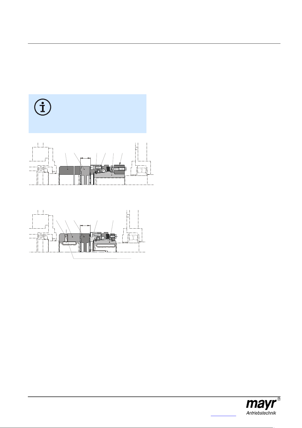
The radial forces, axial forces or transverse
force torques, which are introduced into the
clutch bearing must not exceed the permitted
values acc. Table 1.
Please observe the connection dimensions "a"
and "e" for the output elements as well as the
maximum permitted screw-in depth "b
max.
" in
the pressure flange (3); see Fig. 4 and Table 1
on page 5.
73
a
Ø e
b
max.
EAS®-smartic
®
synchronous clutch Type 48_._ _5._
Sizes 01 – 2 (B.4.17.1.GB)
Design
The EAS®-smartic® clutch is designed as a mechanical
disengaging overload clutch according to the ball detent
principle.
State of Delivery
The EAS®-smartic® clutch is manufacturer-assembled ready for
installation.
If no particular torque adjustment is requested customer-side,
the EAS®-smartic® clutch will always be pre-set to approximately
80 % of the maximum torque.
The reference marking on the adjusting nut (5) or on the locking
ring (21) and the torque specification on the Adjustment Table
(11) directly show the set value.
The hexagon head screw (6/22) is not secured with Loctite on a
pre-set clutch.
Before initial operation of the clutch, please secure the locking
screw (6/22) with Loctite 243.
Please check the state of delivery immediately according to the
Parts List!
mayr ® will take no responsibility for belated complaints.
Please report transport damage immediately to the deliverer.
Please report incomplete delivery and obvious defects to the
manufacturer.
Function
Function in Normal Operation
The EAS®-smartic® clutch Type 481. transmits the torque from
the input shaft onto the output element, which can be mounted
onto the ball bearing supported pressure flange (3) of the clutch.
The torque is transmitted backlash-free over the entire service
lifetime of the clutch.
The EAS®-smartic® Types 484. and 486. connect two shafts and
compensate for shaft misalignments.
Function on Overload
If the set limit torque is exceeded, the clutch disengages. The
torque drops immediately.
The residual torque is approx. 5 - 20 % of the set torque (at
approx. 1500 rpm).
Therefore, the EAS®-smartic® clutch is not load-holding.
An installed limit switch (Item 18 / not included in delivery)
registers the disengagement movement and switches off the
drive.
Once the cause of malfunction has been removed, the clutch is
automatically ready for operation after having reached the
synchronous position:
Re-engagement after 360°.
Installation of the Output Elements (Fig. 4)
The output elements are centred on the deep groove ball
bearing (7) (tolerance H7/h5) and screwed together with the
pressure flange (3).
Please use screws with a strength class of 12.9 with the
corresponding tightening torques acc. Table 1 (tightening
torque Item 14) for screwing onto the pressure flange (3).
The output element must be made of a material with a
minimum tensile strength of approx. 600 N/mm2.
Please contact the manufacturers if this is not the case.
If the resulting radial force from the output element is anywhere
near the centre of the ball bearing, an additional bearing for the
output element is not necessary.
No appreciable axial forces should be transmitted from the
output element onto the clutch pressure flange (3).
Output elements with a very small diameter can be screwed
together with the clutch pressure flange (3) via a customer-side
intermediate flange.
Ball bearings, needle bearings or bearing bushings are suitable
as bearings for the output element, depending on the
installation situation and the installation space.
Please make sure that the output element bearing is designed
as a location bearing (Fig. 4).
Fig. 4
25/11/2011 TK/NU/SU Chr. Mayr GmbH + Co. KG Tel.: +49 8341 804-0
Eichenstraße 1 Fax: +49 8341 804-421
D-87665 Mauerstetten http://www.mayr.com
Page 7 of 18 Germany E-Mail: info@mayr.de

Installation and Operational Instructions for
EAS®-smartic
®
synchronous clutch Type 48_._ _5._
Sizes 01 – 2 (B.4.17.1.GB)
Mounting onto the Shaft
General Shaft Requirements:
Tolerance: up to Ø38 h6.
from Ø38 h6 on clamping ring hubs
from Ø38 k6 on clamping hubs
Surface: finely turned or ground
(Ra = 0,8 µm)
Material: yield point
min. 350 N/mm2 ,
e.g. St60, St70, C45, C60.
1. EAS®-smartic® flange design without shaft coupling
1.1 Clamping ring hub design Type 481._35.0:
The shafts must be solid shafts without a keyway.
Degrease or remove preservation layers on the shafts and
bores before installing the clutch.
Greasy or oily bores or shafts do not transmit the
torque TR specified on order.
Mount the clutch onto the shaft end and bring it into the
correct position.
Tighten the clamping screw (2) using a torque wrench to
the torque stated in Table 1.
1.2 Key design Type 481._25.0:
Mount the clutch onto the shaft end and bring it into the
correct position.
On the EAS®-smartic® with keyway, the clutch must be
secured axially after mounting onto the shaft, e.g. using a
press cover and a screw screwed into the shaft threaded
centre hole.
1.3 Clamping ring hub design with keyway Type 481._45.0:
Degrease or remove preservation layers on the shafts and
bores before installing the clutch.
Greasy or oily bores or shafts do not transmit the
torque TR specified on order.
Mount the clutch onto the shaft end and bring it into the
correct position.
Tighten the clamping screw (2) using a torque wrench to
the torque stated in Table 1.
25/11/2011 TK/NU/SU Chr. Mayr GmbH + Co. KG Tel.: +49 8341 804-0
Eichenstraße 1 Fax: +49 8341 804-421
D-87665 Mauerstetten http://www.mayr.com
Page 8 of 18 Germany E-Mail: info@mayr.de
Installation and Operational Instructions for
Only use PU - compatible lubricants (e.g.
Vaseline)!
After joining both coupling hubs, do not
place axial pressure on the elastomeric
element (15).
Please observe the distance dimension "E"
acc. Figs. 5/6 and Table 1!
E
1 2316 15 14
E
1923 1524 14
Locking set screw depicted 180° offset
EAS®-smartic
®
synchronous clutch Type 48_._ _5._
Sizes 01 – 2 (B.4.17.1.GB)
2. EAS®-smartic® dual-shaft connection with elastomer coupling ROBA®-ES
General:
The elastomer coupling used is backlash-free and requires a
certain axial installation force for joining. The amount of force
required can be reduced by lightly greasing the elastomeric
element (15).
Fig. 5
Clamping (ring) hub design Type 484._ 35._
Fig. 6
Key design Type 484._25._
2.1 Clamping (ring) hub design Type 484._35._:
Install the overload clutch side as described in section 1.1.
Degrease or remove preservation layers on the shafts and
bores before installing the elastomer coupling.
The clamping hub (16) must be completely relaxed before
installation; if necessary loosen the screw (17) by several
thread turns.
Mount the elastomer coupling hub (16) onto the shaft end
and bring it into the correct position.
Tighten the clamping screw (17) using a torque wrench to
the torque stated in Table 1.
Joining the two clutch hubs:
Due to the pre-tensioning of the flexible elastomeric
element (15), an axial installation force is required for
joining both clutch hubs (1 and 16). The amount of force
required can be reduced by lightly greasing the elastomeric
element (15).
2.2 Key design Type 484._25._:
Install the overload clutch side as described in section 1.2.
Mount the elastomer coupling hub onto the shaft end and
bring it into the correct position.
The elastomer coupling hub (23) must be secured axially
onto the shaft, e.g. using a set screw (Item 24, see Fig. 6).
Joining both clutch hubs:
Due to the pre-tensioning of the flexible elastomeric
element (15), an axial installation force is required for
joining both clutch hubs (19 and 23). The amount of force
required can be reduced by lightly greasing the elastomeric
element (15).
2.3 Clamping (ring) hub design with keyway Type 484._45._:
Install the overload clutch side as described in section 1.3.
Degrease or remove preservation layers on the shafts and
bores before installing the elastomer coupling.
The clamping hub (16.1) must be completely relaxed
before installation; if necessary loosen the screw (17) by
several thread turns.
Mount the elastomer coupling hub (16.1) onto the shaft
end and bring it into the correct position.
Tighten the clamping screw (17) using a torque wrench to
the torque stated in Table 1.
Joining both clutch hubs:
Due to the pre-tensioning of the flexible elastomeric
element (15), an axial installation force is required for
joining both clutch hubs (1 and 16.1). The amount of force
required can be reduced by lightly greasing the elastomeric
element (15).
25/11/2011 TK/NU/SU Chr. Mayr GmbH + Co. KG Tel.: +49 8341 804-0
Eichenstraße 1 Fax: +49 8341 804-421
D-87665 Mauerstetten http://www.mayr.com
Page 9 of 18 Germany E-Mail: info@mayr.de

Installation and Operational Instructions for
After joining both coupling halves, please test
and keep to distance dimensions "U1" or "S"
acc. Figs. 7 / 8 / 9 and Table 1!
U
1
1 2332/36 31 26
1934 3135 26
U
1
Locking set screw depicted 180° offset
S
1 2332/36 26
EAS®-smartic
®
synchronous clutch Type 48_._ _5._
Sizes 01 – 2 (B.4.17.1.GB)
3. EAS®-smartic® dual-shaft connection with torsionally rigid shaft coupling ROBA®-DS
General:
On clamping hubs (36/36.1), the clamping screw (33) is lightly
greased manufacturer-side in the thread area.
If the grease layer is washed off, the customer must re-grease
the appropriate parts. For greasing, please use NLGI Class 2
grease with a basic oil viscosity of 220 mm2/s at 40 °C,
e.g. Mobilgrease XHP222.
Fig. 7
Clamping (ring) hub design Type 486._35.0
Fig. 8
Key design Type 486._25.0 (Size 2)
Fig. 9
Type 486._ _5.8 (Single-jointed design)
3.1 EAS®-smartic® Clamping (ring) hub design Type 486._35.0:
On clamping (ring) hubs, the torque is transmitted via
frictional locking, which means that the hub bores and
shafts must be completely grease-free during installation.
Greasy or oily bores or shafts do not transmit the
maximum clutch torque.
The shafts must not have a keyway.
The clamping hubs (32/36) must be completely relaxed
before installation; if necessary the screws (33) must be
loosened by several thread turns.
Mount the first clutch hub of the entire clutch onto the
respective shaft and bring it into the correct position.
Tighten the clamping screw(s) of the first clutch hub using
a torque wrench to the torque stated in Table 1.
Mount the second clutch hub of the entire clutch onto the
respective shaft and bring it into the correct position.
Tighten the clamping screw(s) of the second clutch hub
using a torque wrench to the torque stated in Table 1.
3.2 EAS®-smartic® key design Type 486._25.0:
Mount the ROBA®-DS-side clutch hub (34/36.1) of the
entire clutch onto the respective shaft and bring it into the
correct position.
Tighten the clamping screw (33) or the radial set screw
(35) of this first clutch hub using a torque wrench to the
torque stated in Table 1.
Mount the second EAS®-side clutch hub of the entire clutch
onto the respective shaft.
3.3 EAS®-smartic® Clamping (ring) hub design with keyway Type 486._45.0:
The clamping hubs (32.1/36.1) must be completely relaxed
before installation; if necessary the screws (33) must be
loosened by several thread turns.
Degrease or remove preservation layers on the shafts and
bores before installing the clutch.
Mount the first clutch hub of the entire clutch onto the
respective shaft and bring it into the correct position.
Tighten the clamping screw(s) of the first clutch hub using
a torque wrench to the torque stated in Table 1.
Mount the second clutch hub of the entire clutch onto the
respective shaft and bring it into the correct position.
Tighten the clamping screw(s) of the second clutch hub
using a torque wrench to the torque stated in Table 1.
25/11/2011 TK/NU/SU Chr. Mayr GmbH + Co. KG Tel.: +49 8341 804-0
Eichenstraße 1 Fax: +49 8341 804-421
D-87665 Mauerstetten http://www.mayr.com
Page 10 of 18 Germany E-Mail: info@mayr.de

20
3
0
%
2
5
%
7
5
%
0
%
5
0
%
20
40%
40
30%
60608080100
100
Δ K
w
Angular misalignment
[%]
Δ K [%] Axial displacement
a
Δ K [%] Radial misalignment
r
ΔK
r
ΔK
a
ΔK
w
ΔK
a
Δ
K
w
ΔK
r
ΔKa
Δ
K
w
Installation and Operational Instructions for
EAS®-smartic
®
synchronous clutch Type 48_._ _5._
Sizes 01 – 2 (B.4.17.1.GB)
Permitted Shaft Misalignments
EAS®-smartic® clutch Types 484._ _ 5._ and 486._ _ 5.0
(double-jointed coupling) compensate for angular, axial and
radial shaft misalignments (Figs. 10 and 11) without losing their
backlash-free function.
EAS®-smartic® clutches Type 486._ _ 5.8 (single-jointed
coupling) only compensate for angular and axial shaft
misalignments.
However, the permitted shaft misalignments indicated in
Table 1 must not simultaneously reach their maximum value.
If more than one kind of misalignment takes place
simultaneously, they influence each other.
This means that the permitted misalignment values are
dependent on one another, see Fig. 13.
The sum total of the actual misalignments in percent of the
maximum value must not exceed 100 %.
The misalignment values stated in Table 1 refer to clutch
operation at nominal torque, an ambient temperature of +30 °C
and an operating speed of 1500 rpm.
In other or more extreme clutch operating conditions,
please contact the manufacturers.
Radial Axial Angular
misalignment displacement misalignment
Fig. 10
Type 484._ _ 5._
Axial Radial Angular
displacement misalignment misalignment
Fig. 11
Type 486._ _ 5.0 (double-jointed coupling)
Axial Angular
displacement misalignment
Fig. 12
Type 486._ _ 5.8 (single-jointed coupling)
25/11/2011 TK/NU/SU Chr. Mayr GmbH + Co. KG Tel.: +49 8341 804-0
Eichenstraße 1 Fax: +49 8341 804-421
D-87665 Mauerstetten http://www.mayr.com
Page 11 of 18 Germany E-Mail: info@mayr.de
Fig. 13
Example (Size 0 / Type 486._ _ 5.0):
Axial displacement occurrence ΔKa = 0,36 mm equals 40 % of
the permitted maximum value ΔKa = 0,9 mm.
Angular misalignment occurrence ΔKw = 0,6°, equals 30 % of the
permitted maximum value ΔKw = 2,0°.
=> Permitted radial misalignment Kr = 30 % of the maximum
valueΔKr = 0,2 mm => ΔKr = 0,06 mm
Shaft Alignment
Exact alignment of the shafts reduces the load on the shaft
bearings and increases the clutch lifetime substantially. In very
high-speed drives, we recommend alignment using a suitable
alignment device (e.g. a laser). However, in most of the
applications, shaft alignment using a straight edge in two levels
vertical to each other is sufficient.

Installation and Operational Instructions for
Adjusting the adjusting nut (5/20) or distorting
the cup springs (10) outside of the cup spring
characteristic curve (see Fig. 14) stops the
clutch functioning.
Size 01
Size 0
Size 1
Size 2
Type
Cup spring
layering 3)
[Nm]
Graduation
lines for
M = 80 %
[Nm]
Graduation
lines for
M = 80 %
[Nm]
Graduation
lines for
M = 80 %
[Nm]
Graduation
lines for
M = 80 %
48_.2_5._
1x1 times
1 \ /////// 7
2,7 – 5
19
5 – 10
21
10 – 20
16
20 – 40
25
48_.3_5._
1x2 times
2 \\ ////// 6
5 – 10
19
10 – 20
22
20 – 40
17
40 – 80
26
48_.4_5._
1x3 times
3 \\\ ///// 5
8 – 15
20
15 – 30
23
30 – 60
19
60 – 120
28
48_.5_5._
1x4 times
4 \\\\ //// 4
11 – 20
20
20 – 40
23
40 – 80
19
80 – 160
28
48_.6_5._
1x6 times
6 \\\\\\ // 2
18 – 33
20
35 – 65
24
70 – 125
20
140 – 250
30
48_.7_5._
1x8 times
8 \\\\\\\\ 0
32 – 40
21
60 – 80
27
120 – 160
25
240 – 320
32
48_.8_5._
4)
1x8 times
8 \\\\\\\\ 0
35 – 60
24
70 – 120
31
150 – 240
25
300 – 500
35
Path to
operating range
Force F
Graph of
spring characteristic
curve
Operating
range
Spring path S
EAS®-smartic
®
synchronous clutch Type 48_._ _5._
Sizes 01 – 2 (B.4.17.1.GB)
Torque Adjustment
In order to guarantee low-wear clutch operation, it is essential to
adjust the torque to a sufficiently high service factor (overload
torque to operating torque). Our experience has shown that an
adjustment factor of 1,3 to 3 gives good results.
For very high load changes, high accelerations and uneven
operation, please set the adjustment factor higher.
The respective torque adjustment range is printed on the
Adjustment Table (11). Torque adjustment is carried out by
turning the adjusting nut (5/20). The installed cup springs (10)
are operated in the negative range of the characteristic curve
(see Fig. 14). This means that tightening the adjusting nut
(5/20) causes the spring force to decrease, and loosening the
adjusting nut (5/20) causes the spring force to increase.
If no torque is specified on order, the clutch is pre-set to
approx. 80 % of the maximum torque. The reference marking
and the torque specification show the set value directly.
If no changes to the pre-set clutch torque are required
customer-side, the hexagon head screws (6/22) must
nevertheless be screwed out, painted with Loctite 243 and
screwed back in again by the customer.
Fig. 14
Table 3: Cup Spring Layering and Torque Ranges
Cup Spring Layering
Correct cup spring layering is a prerequisite for problem-free
clutch function and torque adjustment.
On all Sizes, 7 torque ranges (see Table 3) are possible.
Changing the Torque
On clamping ring hub designs Type 48_._35._ and Type 48_._45._
In order to adjust the torque to a different value, simply
1. loosen and unscrew the hexagon head screw (6),
2. adjust the adjusting nut (5) using a hook wrench until the
reference marking shows the required torque value,
3. if necessary, correct the adjusting nut (5) position slightly
until the marking notches between the clamping ring hub
(1/1.1) and the adjusting nut (5) align, and
4. paint the hexagon head screw (6) with Loctite 243 before
screwing it back in again.
On key design Type 48_._25._
In order to adjust the torque to a different value, simply
1. loosen and unscrew the hexagon head screw (22),
2. adjust the adjusting nut (20) using a hook wrench until the
reference marking shows the required torque value,
3. if necessary, correct the adjusting nut (20) position slightly
until the marking notches between the locking ring (21) and
the adjusting nut (20) align, and
4. paint the hexagon head screw (22) with Loctite 243 before
screwing it back in again.
3)
Example: On Type 481.425.0, the cup spring layering is 1x3 times, which means that three cup springs are engaged thrust washer-side
and five cup springs are not engaged (adjusting nut-side) => 3 \\\ ///// 5.
4)
Types 48_.8_5._ require a special pressure flange as well as a special thrust washer.
25/11/2011 TK/NU/SU Chr. Mayr GmbH + Co. KG Tel.: +49 8341 804-0
Eichenstraße 1 Fax: +49 8341 804-421
D-87665 Mauerstetten http://www.mayr.com
Page 12 of 18 Germany E-Mail: info@mayr.de

Installation and Operational Instructions for
1/1.1 1.2 1.3
EAS®-smartic
®
synchronous clutch Type 48_._ _5._
Sizes 01 – 2 (B.4.17.1.GB)
Changing the Torque Adjustment Range by Changing the Cup Spring Layering
If a customer realises that the selected clutch adjustment range
is too high or too low, the cup spring layering (10) on the
respective clutch must be changed (every clutch delivered
contains a maximum of 8 cup springs).
The adjustment scale on the clamping ring (1.2) or the adjusting
nut (20) is no longer applicable after alteration!
Principally, we recommend that modification and re-calibration of
the clutch be carried out at the company mayr ® headquarters,
where we can provide a higher torque adjustment accuracy than
any customer-side alterations.
Changing the cup spring layering (10) between Type
48_.2_5._ and Type 48_.7_5._ is generally possible.
If the required torque lies over the torque range of Type
48_.7_5._, modification to Type 48_.8_5._ is necessary (for
modification, a special pressure flange as well as a special
thrust washer are necessary) or the next larger construction
size must be selected. Types 48_.8_5._ have a max. speed of
250 rpm.
If the required torque lies below the torque range of Type
48_.2_5._, the next smaller construction size must be selected.
Before changing the cup spring layering (10), the clutch must be
removed from the system and placed on a suitable auxiliary
shaft, for example in a vice; it must be re-installed with the
adjusting nut side facing upwards.
When doing this, the clamping ring (1.2) on the clamping ring
design must be re-clamped.
Changing the cup spring layering and torque adjustment on clamping ring design Type 48_._35._ and Type 48_._45._:
1. Turn back the locking screw (6) and remove it from the
clamping ring (1.2).
Please Observe! The locking screw (6) is glued into the
clamping ring (1.2).
2. Turn the adjusting nut (5) back anti-clockwise until the cup
spring package (10) is completely relaxed.
3. Loosen the clamping screw (2) of the clamping ring (1.2)
and remove the clamping ring (1.2) from the hub (1).
4. Screw the adjusting nut (5) completely off the hub (1).
5. Change the cup spring layering (10) acc. Table 3.
6. Screw the adjusting nut (5) clockwise onto the hub (1) up to
contact on the cup springs (10).
7. Push the clamping ring (1.2) into the correct position (for
position of the spring pin (1.3) in the clamping ring (1.2),
please see Fig. 15) up to contact on the hub shoulder (1),
and tighten the clamping screw (2) to the specified torque
(acc. Table 1).
8. Turn the adjusting nut (5) clockwise by the number of
graduation lines acc. Table 3. This achieves a torque of
approx. 80 % of the maximum value on the respective cup
spring layering (10). By turning the adjusting nut (5)
clockwise, the clutch torque can be reduced even further. By
turning the adjusting nut anti-clockwise, the clutch torque
can be increased.
The permitted operating range acc. Fig. 14 must be
observed.
9. One of the marking notches on the adjusting nut (5) must be
aligned with a notch on the clamping ring (1.2). The locking
screw (6) must be painted with Loctite 243 and screwed up
to its limit into the clamping ring (1.2).
10. Remove the clutch from the auxiliary shaft and re-install it
into the system.
Fig. 15
Changing the cup spring layering and torque adjustment on key design Type 48_._25._:
1. Turn back the locking screw (22) and remove it from the
adjusting nut (20).
Please Observe! The locking screw (22) is glued into the
adjusting nut (20).
2. Turn the adjusting nut (20) back anti-clockwise completely
and remove it from the clutch.
3. Remove the locking ring (21) from the hub (19).
4. Change the cup spring layering (10) acc. Table 3.
5. Place the locking ring (21) again up to the cup springs (10)
onto the hub (19).
6. Screw the adjusting nut (20) up to contact on the locking
ring (21) or up to contact of the locking ring (21) on the cup
springs (10) onto the hub (19).
7. Turn the adjusting nut (20) clockwise by the number of
graduation lines acc. Table 3. This achieves a torque of
approx. 80 % of the maximum value on the respective cup
spring layering (10). By turning the adjusting nut (20)
clockwise, the clutch torque can be reduced even further.
By turning the adjusting nut anti-clockwise, the clutch torque
can be increased.
The permitted operating range acc. Fig. 14 must be
observed.
8. One of the marking notches on the adjusting nut (20) must
be aligned with a notch on the locking ring (21). The locking
screw (22) must be painted with Loctite 243 and screwed up
to its limit into the adjusting nut (20).
9. Remove the clutch from the auxiliary shaft and re-install it
into the system.
25/11/2011 TK/NU/SU Chr. Mayr GmbH + Co. KG Tel.: +49 8341 804-0
Eichenstraße 1 Fax: +49 8341 804-421
D-87665 Mauerstetten http://www.mayr.com
Page 13 of 18 Germany E-Mail: info@mayr.de

Installation and Operational Instructions for
SW7 SW7
1,0
1,0
1,0
0,7
Schaltrichtung
SW7
1,2
0,2
EAS®-smartic
®
synchronous clutch Type 48_._ _5._
Sizes 01 – 2 (B.4.17.1.GB)
Limit Switch Installation (Figs. 16 and 17)
The switching direction arrow on the mechanical limit switch
housing cover points in the direction of the adjusting nut (5/20) or
in the stroke direction of the thrust washer (4).
Adjust the switch distances for the contactless and mechanical
limit switch acc. Fig. 16 and Fig. 17.
The distance of the thrust washer (4) to the switching point can
be easily adjusted using a hexagon head screw, wrench
opening 7.
Contactless limit switch
Undamped installation Damped installation
Limit switch is damped Limit switch is not damped
when clutch when clutch
disengages. disengages.
Fig. 16
Mechanical limit switch (only available on Size 2)
Maintenance
The EAS®-smartic® clutch is mainly maintenance-free.
The only maintenance work needed is a regular inspection of
functionality and torque adjustment => yearly.
Special maintenance work may be necessary should the device
be subject to very dirty, dusty or extreme ambient and load
conditions. These include:
Bearing inspection
Tightening torque inspection
Lubrication of the transmission geometries, balls,
recesses and sealing elements
Under these conditions, it may be necessary to carry out
inspections at much shorter intervals.
We recommend that maintenance work is carried out at the
site of manufacture.
Disposal
Electronic Components (Limit switch):
Products which have not been disassembled can be disposed of
under Code No. 160214 (mixed materials) or components under
Code No. 160216, or can be disposed of by a certified disposal
firm.
All steel components:
Steel scrap (Code No. 160117)
Aluminium components:
Non-ferrous metals (Code No. 160118)
Seals, O-rings, V-seals, elastomers:
Plastic (Code No. 160119)
Fig. 17
On EAS®-smartic® clutches Size 01, we generally recommend
the use of smaller, contactless limit switches, e.g. M8 x 1 or
similar devices.
25/11/2011 TK/NU/SU Chr. Mayr GmbH + Co. KG Tel.: +49 8341 804-0
Eichenstraße 1 Fax: +49 8341 804-421
D-87665 Mauerstetten http://www.mayr.com
Page 14 of 18 Germany E-Mail: info@mayr.de

Installation and Operational Instructions for
Malfunction
Possible Causes
Solutions
Premature clutch release
Incorrect torque adjustment
1) Set the system out of operation
2) Check the torque adjustment
3) Secure the adjusting nut
4) If the cause of malfunction cannot be found, the clutch
must be inspected at the place of manufacture
Adjusting nut position has changed
Clutch does not release
on overload
Incorrect torque adjustment
1) Set the system out of operation
2) Check whether foreign bodies influence the clutch
function
3) Check the torque adjustment
4) Secure the adjusting nut
5) If the cause of malfunction cannot be found, the clutch
must be inspected at the place of manufacture
Adjusting nut position has changed
Running noises in normal
operation
Insufficient clutch securement
1) Set the system out of operation
2) Check the clutch securement
3) Check the screw tightening torques
4) Check the torque adjustment and that the adjusting nut
sits securely
5) If the cause of malfunction cannot be found, the clutch
must be inspected at the place of manufacture
Loosened screws
Loosened adjusting nut
mayr ® will take no responsibility or guarantee for replacement parts and accessories which have not been delivered by
mayr ®, or for damage resulting from the use of these products.
EAS®-smartic
®
synchronous clutch Type 48_._ _5._
Sizes 01 – 2 (B.4.17.1.GB)
General Malfunctions / Breakdowns
25/11/2011 TK/NU/SU Chr. Mayr GmbH + Co. KG Tel.: +49 8341 804-0
Eichenstraße 1 Fax: +49 8341 804-421
D-87665 Mauerstetten http://www.mayr.com
Page 15 of 18 Germany E-Mail: info@mayr.de

Installation and Operational Instructions for
Malfunction
Possible Causes
Solutions
Changes in running noise
and / or vibration
occurrence
Type 484.
Incorrect alignment
1) Set the system out of operation
2) Find / resolve the cause of incorrect alignment
(e.g. loose foundation screw, broken motor attachment,
warmth expansion of system components, changes in
coupling installation dimension "E")
3) Check the coupling for wear
Worn elastomeric element, short-term
torque transmission via metal contact
1) Set the system out of operation
2) Dismantle the coupling and remove the remainders of the
elastomeric element
3) Check the coupling parts and replace if damaged
4) Insert new elastomeric element, mount the coupling parts
5) Check the alignment and correct if necessary
Tensioning and clamping screws or locking
set screw for axial hub securement are
loose
1) Set the system out of operation
2) Check the coupling alignment
3) Tighten the tensioning and clamping screws for axial hub
securement as well as connection screws to the required
torque or tighten the locking set screw and secure it
against self-loosening using sealing lacquer
4) Check the coupling for wear
Loose connection screws
Cam breakage
Type 484.
Worn elastomeric element, torque
transmission via metal contact
1) Set the system out of operation
2) Replace the entire coupling
3) Check the alignment
Cam breakage due to high impact energy /
overloading
1) Set the system out of operation
2) Replace the entire coupling
3) Check the alignment
4) Find the cause of overload
Operating parameters are not appropriate
for the coupling performance
1) Set the system out of operation
2) Check the operating parameters and select a suitable
coupling (observe installation space)
3) Install a new coupling
4) Check the alignment
Operating errors on the system unit by
exceeding coupling characteristic data
1) Set the system out of operation
2) Check the coupling dimensioning
3) Replace the entire coupling
4) Check the alignment
5) Train and advise operating personnel
mayr ® will take no responsibility or guarantee for replacement parts and accessories which have not been delivered by
mayr ®, or for damage resulting from the use of these products.
EAS®-smartic
®
synchronous clutch Type 48_._ _5._
Sizes 01 – 2 (B.4.17.1.GB)
Malfunctions / Breakdowns Type 484._ _5._
25/11/2011 TK/NU/SU Chr. Mayr GmbH + Co. KG Tel.: +49 8341 804-0
Eichenstraße 1 Fax: +49 8341 804-421
D-87665 Mauerstetten http://www.mayr.com
Page 16 of 18 Germany E-Mail: info@mayr.de

Installation and Operational Instructions for
Malfunction
Possible Causes
Solutions
Premature wear on the
elastomeric element
Type 484.
Incorrect alignment
1) Set the system out of operation
2) Find / resolve the cause of incorrect alignment
(e.g. loose foundation screw, broken motor attachment,
warmth expansion of system components, changes in
coupling installation dimension "E")
3) Check the coupling for wear
4) Insert new elastomeric element
e.g. contact with aggressive fluids / oils,
ozone influence,
too high ambient temperatures etc.,
which cause physical changes in the
elastomeric element
1) Set the system out of operation
2) Dismantle the coupling and remove the remainders of the
elastomeric element
3) Check the coupling parts and replace if damaged
4) Insert new elastomeric element, mount the coupling parts
5) Check the alignment and correct if necessary
6) Make sure that further physical changes in the
elastomeric element can be excluded
The ambient or contact temperatures
permitted for the elastomeric element are
exceeded
1) Set the system out of operation
2) Dismantle the coupling and remove the remainders of the
elastomeric element
3) Check the ambient or contact temperature and regulate
them (possibly using other elastomeric element materials)
4) Check the coupling parts and replace if damaged
5) Insert new elastomeric element, mount the coupling parts
6) Check the alignment and correct if necessary
Premature wear on the
elastomeric element
(material liquefaction in
the elastomeric element
tooth interior)
Type 484.
Drive vibrations
1) Set the system out of operation
2) Dismantle the coupling and remove the remainders of the
elastomeric element
3) Determine the cause of vibration (maybe the problem can
be resolved by using an elastomeric element with lower or
higher shore hardness)
4) Check the coupling parts and replace if damaged
5) Insert new elastomeric element, mount the coupling parts
6) Check the alignment and correct if necessary
mayr ® will take no responsibility or guarantee for replacement parts and accessories which have not been delivered by
mayr ®, or for damage resulting from the use of these products.
EAS®-smartic
®
synchronous clutch Type 48_._ _5._
Sizes 01 – 2 (B.4.17.1.GB)
Malfunctions / Breakdowns Type 484._ _5._ (continued)
25/11/2011 TK/NU/SU Chr. Mayr GmbH + Co. KG Tel.: +49 8341 804-0
Eichenstraße 1 Fax: +49 8341 804-421
D-87665 Mauerstetten http://www.mayr.com
Page 17 of 18 Germany E-Mail: info@mayr.de

Installation and Operational Instructions for
Malfunction
Possible Causes
Solutions
Changes in running noise
and / or vibration
occurrence
Type 486.
Incorrect alignment, incorrect installation
0) Set the system out of operation
1) Find and remove the cause of incorrect alignment
2) Check the coupling for wear
Loose connecting screws,
minor friction corrosion under the screw
head and on the disk pack
1) Set the system out of operation
2) Check the coupling parts and replace if damaged
3) Tighten the connecting screws to the specified torque
4) Check the alignment and correct if necessary
Tensioning screws or locking set screw for
axial securement of the hubs are loose
1) Set the system out of operation
2) Check the coupling alignment
3) Tighten the tensioning and clamping screws for axial hub
securement to the required torque or tighten the locking
set screw and secure it against self-loosening using
sealing lacquer
4) Check the coupling for wear
Disk pack breakage
Type 486.
Disk pack breakage due to high load
impacts / overload
1) Set the system out of operation
2) Dismantle the coupling and remove the remainders of the
disk packs
3) Check the coupling parts and replace if damaged
4) Find the cause of overload and remove it
Operating parameters are not appropriate
for the coupling performance
1) Set the system out of operation
2) Check the operating parameters and select a suitable
coupling (observe installation space)
3) Install a new coupling
4) Check the alignment
Incorrect operation of the system unit
1) Set the system out of operation
2) Dismantle the coupling and remove the remainders of the
disk packs
3) Check the coupling parts and replace if damaged
4) Train and advise operating personnel
Disk pack / connecting
screw cracks or breakage
Type 486.
Drive vibrations
1) Set the system out of operation
2) Dismantle the coupling and remove the remainders of the
disk packs
3) Check the coupling parts and replace if damaged
4) Check the alignment and correct if necessary
5) Find the cause of vibration and remove it
mayr ® will take no responsibility or guarantee for replacement parts and accessories which have not been delivered by
mayr ®, or for damage resulting from the use of these products.
EAS®-smartic
®
synchronous clutch Type 48_._ _5._
Sizes 01 – 2 (B.4.17.1.GB)
Malfunctions / Breakdowns Type 486._ _5._
25/11/2011 TK/NU/SU Chr. Mayr GmbH + Co. KG Tel.: +49 8341 804-0
Eichenstraße 1 Fax: +49 8341 804-421
D-87665 Mauerstetten http://www.mayr.com
Page 18 of 18 Germany E-Mail: info@mayr.de
 Loading...