

Page 1
1 | P a g e
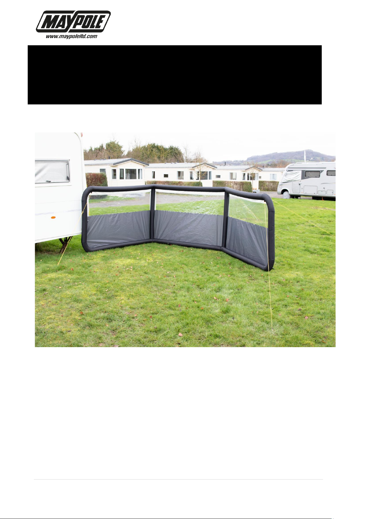
3 PANEL SINGLE POINT INFLATABLE
WINDBREAK (MP9526) USER GUIDE
Please read this user guide before attempting to set up your windbreak.
Follow the user guide carefully and keep for future reference.
A copy of the user guide is also available on our website
www.maypoleltd.com
Page 2

2 | P a g e
3 PANEL SINGLE POINT INFLATABLE
WINDBREAK (MP9526) USER GUIDE
WARNING – GENERAL SAFETY
• Not to be used in extreme weather conditions.
CARE OF YOUR WINDBREAK
• Allow material to dry completely before storing in the storage bag provided.
• Remove dirt with a soft sponge and warm water. DO NOT use detergent.
• DO NOT expose to sparks, flames or other sources of ignition.
CONTENTS
Windbreak x 1
Window covers x 3
Air Pump x 1
Steel pegs x 13
Guy ropes x 6
Carry bag x 1
BEFORE USE
Choose a clear site that is flat. Remove any sharp objects from the pitching area which
could be dangerous or potentially damage the fabric or puncture the air beams.
Page 3
3 | P a g e
3 PANEL SINGLE POINT INFLATABLE
WINDBREAK (MP9526) USER GUIDE
PITCHING INSTRUCTIONS
Recommended 2 person Pitch.
Remove the windbreak from the carry bag and place flat on the ground.
There are 2 valves on the windbreak. Locate the first valve and unscrew the top cap.
Locate the second valve and make sure both the top & bottom caps are fully tightened.
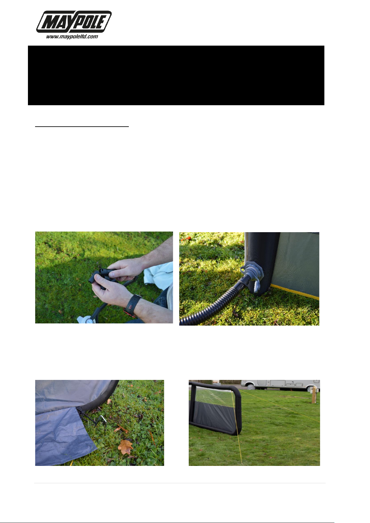
Connect the large adaptor (FIG 1) to the hand pump. Insert the adaptor into the top cap
on the valve (FIG 2). Inflate the air beam to approx. 6-7 PSI. Remove the adaptor from
the valve and securely tighten the top cap. WARNING: WHEN INFLATING; DO NOT
EXCEED A PRESSURE OF OVER 7 PSI. IN STRONG SUNLIGHT & IN HOT
TEMPERATURES REDUCE THE PRESSURE TO 4-5 PSI.
FIG 1 FIG 2
Starting from one end; peg down the bungee eyelet at the base of the air beam (FIG 3).
Use 2 guy ropes to hold each panel in place – ensuring the air beams are vertical (FIG
4)
FIG 3 FIG 4
Page 4

4 | P a g e
3 PANEL SINGLE POINT INFLATABLE
WINDBREAK (MP9526) USER GUIDE
Repeat this process for each section of the windbreak.
It is recommended each peg is driven fully into the ground at an angle of 45 Degrees
away from the pegging point. Tension each guy rope using the guy adjusters (FIG 5).
FIG 5
Adjust the windbreak to the desired shape and position ensuring all air beams remain
vertical.
Peg down the middle eyelets found at the base of each panel.
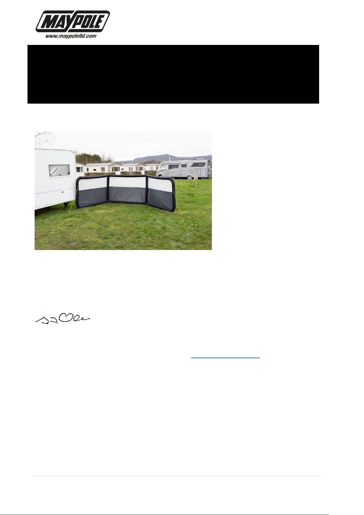
The windows can be covered by attaching the panels with the elasticated toggles (FIG
6). FIG 7 shows the window panels attached.
FIG 6
Page 5
5 | P a g e
3 PANEL SINGLE POINT INFLATABLE
WINDBREAK (MP9526) USER GUIDE
FIG 7
To deflate the air beams unscrew the bottom cap on both valves and the air will be
released.
WARNING – Be aware of sudden loud noise caused by air escaping when
deflating.
Technical Manager Maypole Ltd November 2020
Email: [email protected] Web: www.maypoleltd.com
 Loading...