


Digital Wireless Reversing Camera System (MP7410) &
Additional Camera MP7411
2
INTRODUCTION
The MP7410 digital wireless reversing camera system with built in transmitter when used as described will improve your ability to
see behind your car, camper, trailer, or horse box. Numerous measures in quality control have been taken to ensure that your
product arrives in top condition and will perform to your satisfaction.
Please carefully read and follow the following safety and operating instructions.
IMPORTANT SAFETY INSTRUCTIONS
Before You Install
If you are not confident working with 12V/24V DC vehicle wiring, removing and reinstalling interior panels, carpeting, dashboards
or other components of your vehicle, consider having the camera system professionally installed.
Carefully consider the location of any new holes before drilling. It is important to take precautions to prevent damage to the
vehicle’s electrical and fuel system.
Interference
This device is immune from interference from other wireless devices; Bluetooth, mobile telephones, Wi-FI routers, power lines
and other various electrical equipment.
Repair
The camera system contains no user serviceable parts and should not be opened. Any attempt at modification or repair by the
user will entail the loss of your guarantee.
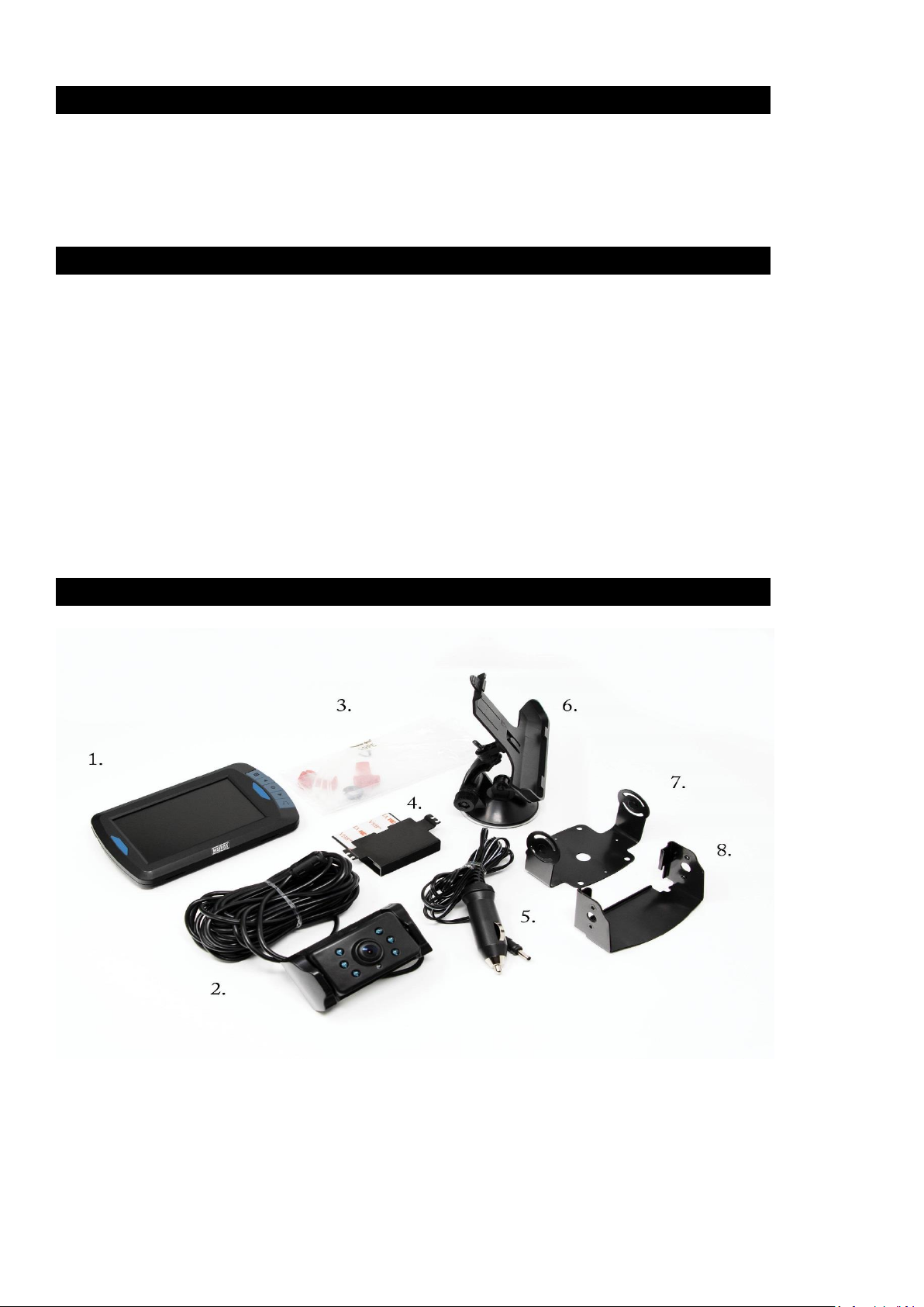
COMPONENTS
1). Monitor 2). Camera
3). Mounting accessories 4). Flush mounting plate
5). Monitor power cable 6). Mounting arm
7 & 8). Surface mounting plates
3
INSTALLATION
These instructions do not apply to all vehicles. They are only meant as a general guide due to the number of different makes &
models. For vehicle specific questions contact your vehicle’s manufacturer.
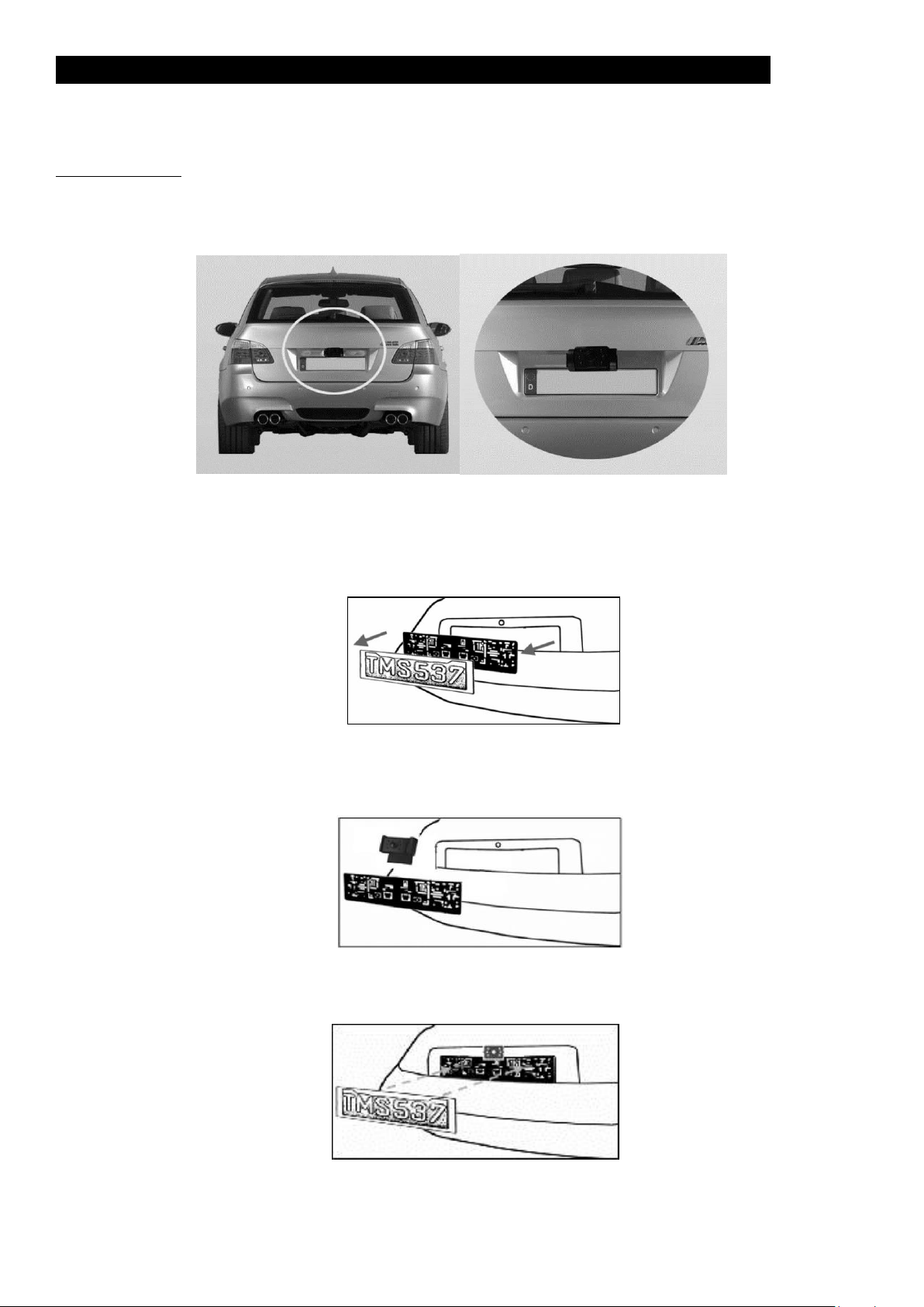
Camera installation
There are several ways to mount the camera on the back of your car. But the most convenient is to mount it near the number
plate. Supplied within the kit are two mounting plates; one is intended to be fixed behind the number plate, and the other is for
surface mounted installation. Once the camera is affixed to either mounting plate the camera can be adjusted manually on its
vertical axis. Ensure that the cameras field of vision is not obstructed.
Bracket for licence plate mounting
A1. Remove the rear number plate; the plate may be affixed either directly to the vehicle or via a mounting bracket.
Dependant on the vehicle, screws/bolts or sticky pads may be used.
A2. If your vehicle utilizes a mounting bracket, position the camera mounting bracket (together with camera) behind the
number plate bracket if possible. Secure number plate bracket and mounting plates back to the vehicle with the original bracket
fixings.
A3. The number plate can then be remounted onto the bracket. If your vehicle is not supplied with a number plate mounting
bracket the camera can be mounted directly onto the number plate.
NOTE: ENSURE THAT THE CAMERA OR BRACKET DOES NOT OBSCURE ANY PART OF THE VEHICLE NUMBER PLATE!

4
Bracket for mounting direct to vehicle body
B. Remove the above number plate mounting bracket and fit the upper part of the two piece metal bracket with 4 off screws
(PA 2.6x14) as per image B1. The second (lower) part of the bracket can then be mounted to a suitable area of the vehicle body,
as per B2. All holes made in the vehicle bodywork whilst mounting lower bracket B2 should be treated with an appropriate rust
inhibitor prior to fitment of bracket. The two parts of the bracket can then be assembled together as shown below.
B1
B2
Electrical connection
1. Choose a routing path for the camera’s power cable through the vehicle’s body to the reverse light circuit. If in doubt, seek
professional installation assistance.
2. Some vehicles may have a hole available to pass the wire through, such as where the number plate light is mounted, or you
can drill a hole close to where the power cable is attached to the camera. Once you have chosen where the cable will enter
the vehicle’s body, remove the camera. If you are able to use an existing opening, skip the next two steps.
3. Before you drill a hole you MUST CHECK and see WHAT IS BEHIND WHERE YOU ARE DRILLING. If there are any vehicle
components, such as electrical parts or fuel system components behind where you are drilling, you must take whatever
precaution is necessary not to damage them. Remove the number plate and camera before drilling.
4. After you have drilled the hole, apply an appropriate rust inhibitor, insert the supplied grommet, then pass the camera cables
through the grommet into the vehicle. You must use the
grommet to prevent the metal edge of the hole from cutting the
camera cable. Next you’ll need to find the vehicle’s reverse
lights. Turn the vehicle’s ignition key to the accessory position,
engage the parking brake and put the car in reverse. WARNING :
DO NOT start the engine ! Look at the vehicle’s tail lights to see
where the reverse lights are located, they are the white lights.
To locate the reverse light’s 12V/24V + wire it will be necessary
to gain access to the rear of the vehicle’s tail light. For help
locating the vehicle’s reverse light circuit contact your vehicle’s
manufacturer for vehicle specific wiring diagrams.
5. Once you have located the reverse light circuit you will have to
route the camera cable to that location. You must securely
fasten the power cable to prevent it from being caught on any
vehicle component such as the boot hinge. Never route the
cable on the outside of the vehicle! The reverse light sockets on most vehicles have two wires connected to them. Usually
the negative wire is black and the positive wire is a coloured wire. If you are uncertain about the wiring, you can use a 12V/24V
multi meter available at most auto parts stores to determine which the positive wire is. Follow the manufacturer’s instructions
for the safe use of the multi meter.
6. After determining which wire is the positive and which is the negative, turn off the ignition key, then remove the battery’s
negative cable.
7. Splice the red wire using the supplied in-line wire connectors to the reverse light’s positive (+) wire. Use a set of slip joint
pliers to squeeze the TAP and insure good connection.

5
8. Next splice the black wire of the camera power cable to the reverse light negative (-) wire or ground.
9. Replace the reverse light bulb, and then re-install the light socket. Secure all the wires with cable ties or electrical tape.
10. Re-attach the negative battery cable to the battery.
Note: The camera can also be connected to an alternative ignition switched supply if the view from the camera is required
permanently whilst the vehicle is in use – this could be useful if the camera is installed in horsebox etc. Connection method is as
above.
Monitor Installation
When choosing a location to mount the monitor, make sure the monitor is in an area that will not obstruct your vision while
driving.
1. Before mounting the monitor, clean the mounting surface well.
2. Position the suction mount to the smooth surface which suits your requirement.
3. Press the suction cap against the smooth surface and press the lock down to attach and fix the mount to the surface.
4. Snap in the monitor to the suction mount.
5. Adjust the mounting arms to suit your view angle to the monitor and tighten the screws on the mount to fix the position.
6. Route the power cable to the vehicle’s cigarette lighter socket 12V/24V power outlet. The cable must not interfere with the
safe operation of the vehicle.
7. Insert the small 12V/24V DC plug of the power cable into the right side of the monitor.
8. Plug the 12V/24V cigarette lighter plug into the vehicle’s cigarette lighter socket.
To maximize the effectiveness of the suction mount, it is recommended that the application be performed under the following
conditions:
• Surface temperature should be between 21 and 38 degrees Celsius.
• Application below 10 degrees should be avoided.
• Application should not occur in direct sunlight.
Mounting should be protected from exposure to direct sunlight for a period of 24 hours.
NOTE: UNDER EXTREME BRIGHT LIGHT CONDITIONS, THE SCREEN IMAGE MAY TAKE A FEW SECONDS TO STABLIZE. PLEASE WAIT
UNTIL THE IMAGE HAS STABLIZED BEFORE REVERSING.
System testing
1. Reattach the vehicle’s negative battery cable.
2. Turn the ignition key to the accessory position, do not start the vehicle.
3. Engage the parking brake, and then put the gear lever in the reverse position.
4. After testing the unit and you are satisfied with the route you have chosen for the cabling, you are ready to complete
installation.
5. Route all wires behind interior panels or under carpeting so they are hidden. Use supplied cable ties to neatly gather any
excess wire.

6
OPERATION
Please always pair the monitor and camera before the 1st operation, please refer to below “Pairing” step.
There are 5 control buttons available for users to have their controls:
Power button
Press the POWER button to supply power to the monitor. The picture on the monitor will automatically turn on when the vehicle
is in reverse gear (when already paired as described below). When the monitor gets an image, the blue LED will be lit. If there is
power to the monitor, but the monitor does not get any image, the blue LED will blink on and off. When the monitor power is off,
no picture can appear on the screen and the blue LED will be off.
Menu button
Press the Menu button to enter the menu screen as shown below: Picture SPEC, Picture Direction, Pair and Product Information.
Select the desired menu by pressing the arrow buttons and confirm your
choice with the Power Button.
Pairing:
Two cameras can be paired to the display.
Ensuring that power is first being supplied to the camera by placing the vehicle into reverse with the ignition on but engine off,
press the menu button, select the “Pair” icon using the arrow buttons and enter the menu using the Power button. Select which
channel (A or B) you wish the camera to connect and select with power button. Note : each camera requires a different channel.
Press and hold the rubber button on the bottom of camera unit for at least 2 seconds.
Once the monitor correctly receives a signal from the camera the monitor will display “OK” and the view from the camera will
appear on the screen. The camera is now paired with the monitor and will automatically connect from now on. A second camera
(MP7411, if purchased) can be paired in the same way on the other channel.
If two cameras are in use a priority camera can be selected by selecting the ‘master’ option; selecting channel A or B will determine
which camera will be displayed on the screen if a signal is simultaneously received by both cameras. Press the menu button to exit
the selection; alternatively the screen will automatically exit after 30 seconds.
Menu button
Guideline button
Power button
Arrow button
Arrow button

7
Picture SPEC:
Choose the menu “Picture Spec” with the arrow buttons and confirm with the
Power Button. In this menu you can change brightness, contrast or colour of
the picture. Chose the desired function with the arrow buttons, confirm by
pressing the Power button and change the values with the arrow buttons. To
save the settings and exit the screen press the menu button.
Orientation:
In the Menu “Picture direction” you can change the orientation of the picture. This allows you to mount the camera and monitor
in any orientation and still see a correctly oriented picture on the monitor. Simply enter the “Picture direction” menu and pressing
the Power button. The orientation of the picture will change every time pressing the Power button.
Select your desired picture orientation, then save the settings and exit the screen by pressing the menu button.
Guideline button
This device has the option to overlay distance guidelines on
the display. This helps you to judge the distance between
objects behind your car. By pressing the guideline button,
you can switch this option on and off.

8
TECHNICAL SPECIFICATIONS
Camera
Operating Voltage
8-28V DC
Current consumption
<120mA(IRLED OFF); <170mA(IRLED ON);
Image sensor
CMOS
No. of pixel
640x480
Optical lens
F1.7mm / F2.4
Transmission frequency
2.4G (ISM band)
RF transmission distance (open space)
25M
IP Rating
65
LCD monitor
Operation Voltage
8-28V DC
Standby Current
<50mA
Operation Current
<200mA
LCD display screen size
10.9cm / 4.3 inch
No. of pixel
480x272
Operation temperature
-10 to +45 degree Celsius
This model may be operated in EU countries.
ENVIRONMENTAL PROTECTION
Waste electrical products should not be disposed of with household waste. Please recycle where facilities exist.
Check with your local authority or retailer for recycling advice.
Email: sales@maypoleltd.co.uk Web: www.maypole.ltd.uk
 Loading...