

Page 1

MAYPOLE STARTER CHARGER MP725
230V
- 50
/60 Hz.
Input Voltage
INSTRUCTIONS AND SPECIFICATIONS
Charge / Start Voltage
CE Norm Rated Charging Current
Max. Charging Current
CE Norm Starting Current
Max. Starting Current (0V)
Recommended Input Fuse
Output Fuse
Charging Outputs
Weight
12V or 24V
30 A
75 A
300A
450A
32A
4 x 80A
4
24.8Kg
CONNECTION TO THE POWER SUPPLY
Check that the supply voltage is the same as the voltage required by the machine. This machine must be connected through an
isolator and fuse of the correct rating (32 amps). Not suitable for connection to a 13 amp plug, use of lower rated supplies (13Amp
plug) will reduce the capacity of the machine in “Start” mode and may lead to blown fuses, charging functions will not be affected.
Mains Lead
Wire Colour
Yellow/Green ................... Earth
Brown ............................... Live
Blue .................................. Neutral
Connection
THE YELLOW / GREEN WIRE IN THE MAINS CABLE OF THIS MACHINE MUST ALWAYS BE CONNECTED TO EARTH
SAFETY
Isolate the machine from the power supply before removing any panels or carrying out any maintenance work. Electrical repairs
should only be carried out by a competent electrician.
Ensure that cables are regularly inspected and kept in good condition. If using an extension cable the conductor size should be as
great or greater than the conductor size of the cable fitted to the machine. Unreel extension cables fully to prevent heat build up.
Do not operate the machine in wet or damp conditions. Before charging ensure that the battery terminals are clean and that the
cells contain the correct level of electrolyte. Top up with distilled water if required.
Battery acid is highly corrosive. If spillage occurs wash off with plenty of cold water. Avoid contact with eyes and skin.
During charging explosive gas is formed in the battery, avoid sparks and naked flames, switch off charger before connecting to or
disconnecting from the battery. Always use in a well ventilated area and loosen battery filler caps to assist gas dispersal and
prevent pressure build up. Remember to re-tighten filler caps after charging.
Some batteries are "sealed for life". These batteries have fixed filler caps and should not require topping up. They will however
still form explosive gas and the same precautions should be taken to avoid sparks etc.
Position charger and leads carefully. Avoid accidental contact with moving or hot parts in the engine compartment ie cooling fan,
exhaust manifold.
THERMAL PROTECTION DEVICE
This machine is fitted with a thermal cut out which will switch off the mains supply to the machine if its temperature rises above a
normal operating level. This protects the machine from damage.
The cut out will re-set automatically when the machine temperature returns to normal, switching on the machine. While the cut out
is operated the mains supply light on the ON / OFF switch will not light.
FUSIBLE LINK
The machine is protected from overload by a fuse. Reverse polarity connection, incorrect charging voltage or overloaded output
may cause this fuse to blow. Always use replacement fuses of the correct type. Always tighten fuse fixing nuts carefully.
Never use other components as temporary replacements for the fuse as serious damage to the charger may result which will not
be covered by warranty.
Always disconnect the machine from the mains and the battery before replacing the fuse.
PROCEDURE FOR BATTERY CHARGING
A complete charging cycle should be carried out slowly to prevent overheating and possible damage to the battery, please consult
the battery manufacturers charging instructions to establish the correct charging current in Amps. The charging rate in amps.
should be approx. 10% of the battery capacity rating in ampere hours.
Batteries should never be over charged (heavy gassing occurs and the battery overheats) this will damage the battery.
A hydrometer or voltmeter should be used to monitor the charging process. A low charging current reading on the ammeter during
charging may indicate that the battery is either fully charged or faulty. Batteries should not be left on charge when the charging
cycle is complete.
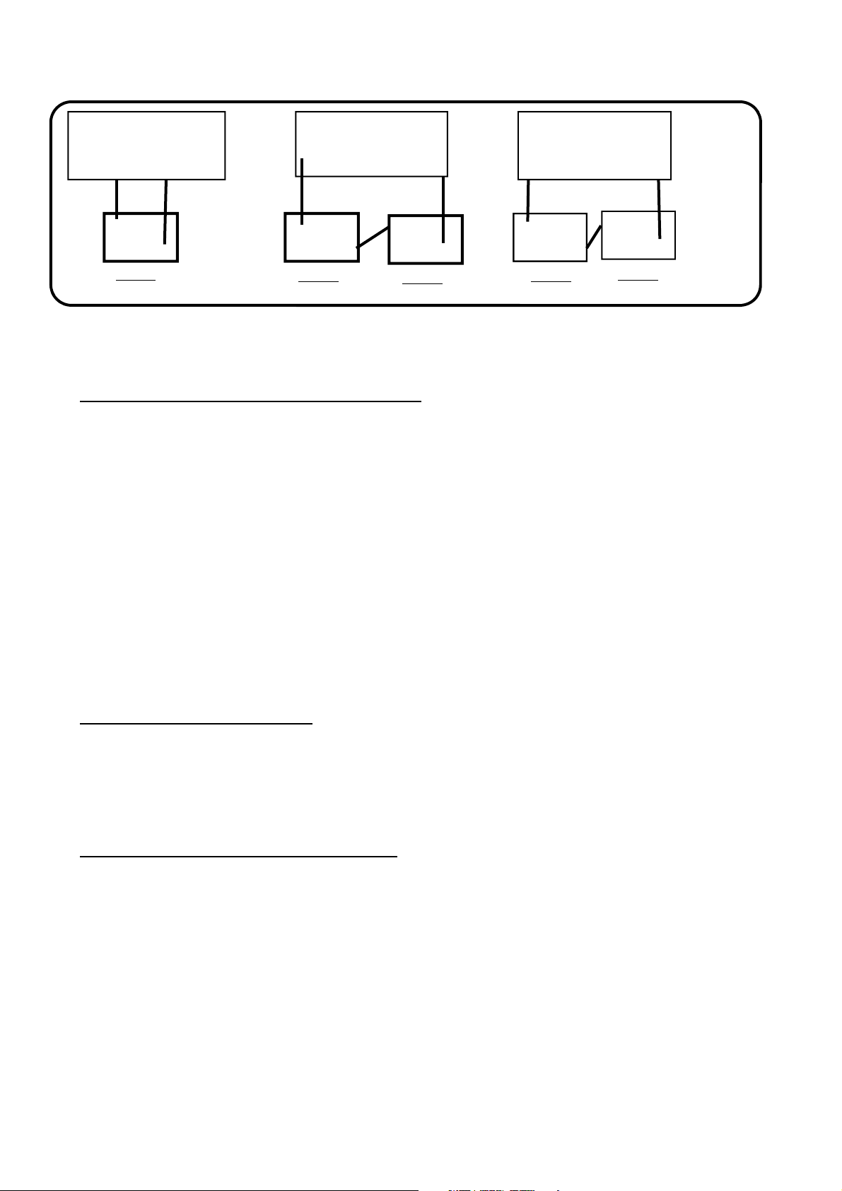
This machine is designed to charge at 12 Volts or 24 Volts and may be used to charge 6 Volt 12 Volt or 24 Volt batteries as below.
Page 2
+ 12v
+
+
+ 12v
24v
12v
12v
+
+ 12v
+
CHARGER
--
12v
BATTERY
BATTERY CONNECTION LAYOUTS FOR 6 / 12 / 24 Volt for STARTING AND CHARGING
A - one 12V battery; plug-in at 12V
B - two 6V batteries; connection in series; plug-in at 12V
C - two 12V batteries; connection in series; plug-in at 24V
+
CHARGER --
6v
--
BATTERY
6v
BATTERY
--
+
CHARGER
BATTERY
BATTERY
--
--
--
OPERATING INSTRUCTIONS FOR BATTERY CHARGING
1/ Please consult the vehicle manufacturer or the vehicle handbook to establish the correct charging procedure for
your vehicle.
2/ We recommend the disconnection of the red positive (+) battery lead on the vehicle before charging. Caution!
When disconnecting the battery or removing fuses, engine management, alarm or audio equipment may be affected.
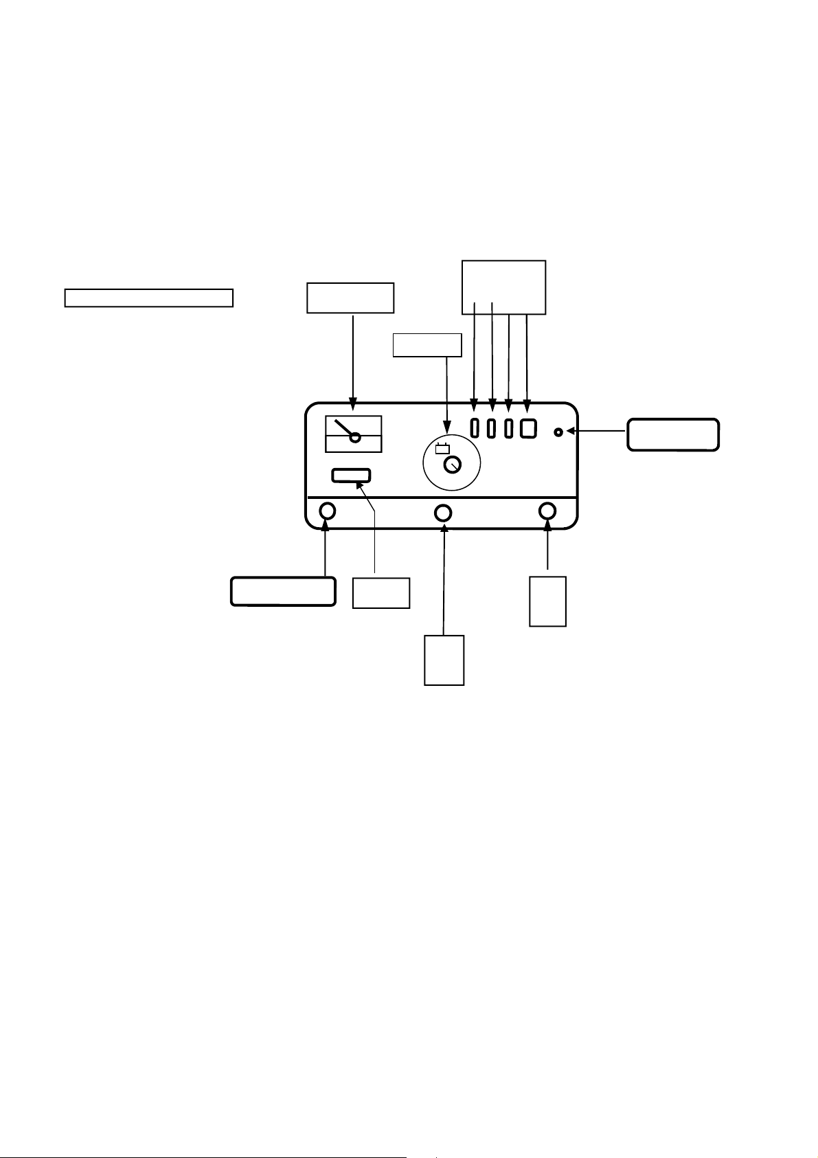
3/ Check that switch "1" is in the "OFF" position and the current control switches are set as follows,
Switch"2" is set to "CHARGE"
Switch "3" is set to level "MIN"
Switch “4” is set to “1"
4/ Connect the red charger lead to the "+12" or the "+24" output terminal post on the charger to match the voltage of
the battery being charged.
5/ Connect the Red (+) charger lead to the Red POSITIVE (+) terminal of the battery.
6/ Connect the Black (-) charger lead to the Black NEGATIVE (-) terminal of the battery.
7/ Connect to the mains supply and switch the charger ON using switch “1”.
8/ Set the rotary timer switch to the required charging time in minutes. If you do not wish to use the timer for
long slow charging cycles, the rotary timer switch should be set to the battery symbol on the timer scale. In
this position the timer does not operate and the charger will remain on.
9/ Set the current control switches "3" and "4" to the required current flow on the ammeter.
10/ After charging switch off and disconnect the charger from the mains. Remove the charging leads one at a time,
refit the red positive (+) battery lead tighten filler caps and replace any terminal covers.
PROCEDURE FOR ENGINE STARTING
This machine is designed to start 12 Volt or 24 Volt vehicles. The starting procedures must always be carried out
with the vehicle battery connected.
To prevent damage to glow plugs/heaters when starting diesel engines pre-heat the plug before using the "boost"
setting on the charger to start the engine.
Do not operate switches on the charger while the starter motor is being used as damage to the switches may occur.
Long periods of use on boost may cause the fusible link to blow and should therefore be avoided.
OPERATING INSTRUCTION FOR ENGINE STARTING
1/ Please consult the vehicle manufacturer or the vehicle handbook to establish the correct starting procedure for
your vehicle.
2/ In severe weather conditions or when starting larger engines a pre-charge period of 10-15 minutes is
recommended particularly if the battery is completely flat.
3/ Ensure that the mains switch "1" is set to "OFF" and the current selector switch "2" is set to "START".
4/ Connect the red charger lead to the "+12" or the "+24" terminal post on the charger to match the battery voltage.
5/ Connect the red charger lead to the red POSITIVE (+) terminal of the battery.
6/ Connect the black charger lead to the black NEGATIVE (-) terminal of the battery.
7/ Connect to the mains supply and switch the charger "ON" using switch "1", after a few seconds start the engine in
the normal way.
8/ Do not operate the starter motor for more than 3 seconds at each attempt with the charger connected and set to
“START” or the output fuse may blow.
9/ To avoid damage to the machine, rapid overheating or blown fuses, observe the operating cycle displayed on the
machine data plate. If the vehicle fails to start, allow the charger to cool before attempting to start the vehicle again.
Please see data panel on the charger.
Page 3
30
10
60
+
S
witch no
’s
TOP VIEW OF MACHINE
+
Mains Input
10/ As soon as the engine starts switch off the charger, disconnect from the mains supply and remove the charger
leads from the battery one at a time, replace battery terminal covers. Keep clear of hot or moving parts in the engine
compartment!
11/ The machine is equipped with a 25A overload circuit breaker on the front panel close to the On/Off switch. This is
to protect against sustained overload, if this cut out operates during a starting cycle, switch off the machine press
and reset the cut out, switch the machine back on and try again
Note.
Leaving the charger connected to the battery with “Start” selected for longer periods will damage the battery.
AMMETER
4 3 2 1
Circuit Breaker
_
Negative Lead
FUSE
12v
24V
2013/11
 Loading...