

Page 1
(1)
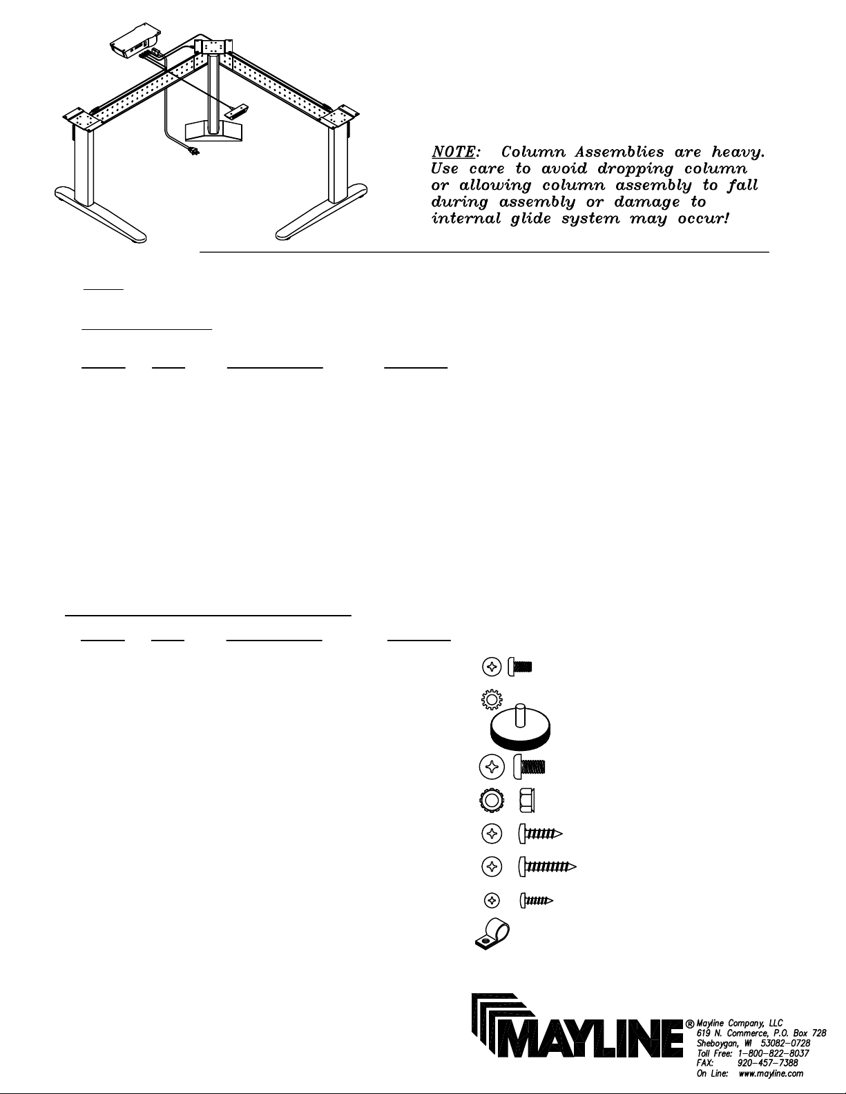
ASSEMBLY INSTRUCTIONS for
TRIPLE COLUMN XR BASE
NOTE: Please count and inspect all pieces before disposing of any carton or packing materials.
COMPONENTS:
REF. # QTY. DESCRIPTION PART No.
1 3 LIFT ACTUATOR Z460
2 2 XR FOOT A7310
3 1 14" WELDED FOOT A7299
4 1 R.H. CHANNEL CALL~~
5 1 L.H. CHANNEL CALL~~
6 3 TOP PLATE B6969
7 1 CORNER BRACKET A7292
8 1 CONTROL BOX Z462
9 1 MEMORY SWITCH Z463
10 1 MAIN CABLE Z467
11 1 39.37 CABLE Z464
12 2 78.74 CABLE Z465
When ordering components, specific size information may be required.
Contact a Mayline Customer Service Representative. 1-800-822-8037
~~Denotes Size
HARDWARE BAG (PART No. A7312) *for individual item, order that part number
REF. # QTY. DESCRIPTION PART No.
E1 24 M6 X 16mm SCREW X419*
E2 24 STAR WASHER W29*
E3 2 GLIDE Q607*
E4 8 1/4-20 X 1/2 SCREW X352*
E5 8 1/4-20 KEPS NUT T126*
E6 8 #10 X 3/4" SCREW X11*
E7 12 #10 X 1" SCREW X12*
E8 2 #6 X 5/8" SCREW X10*
E9 4 CABLE CLAMP F191*
Page 2
(2)
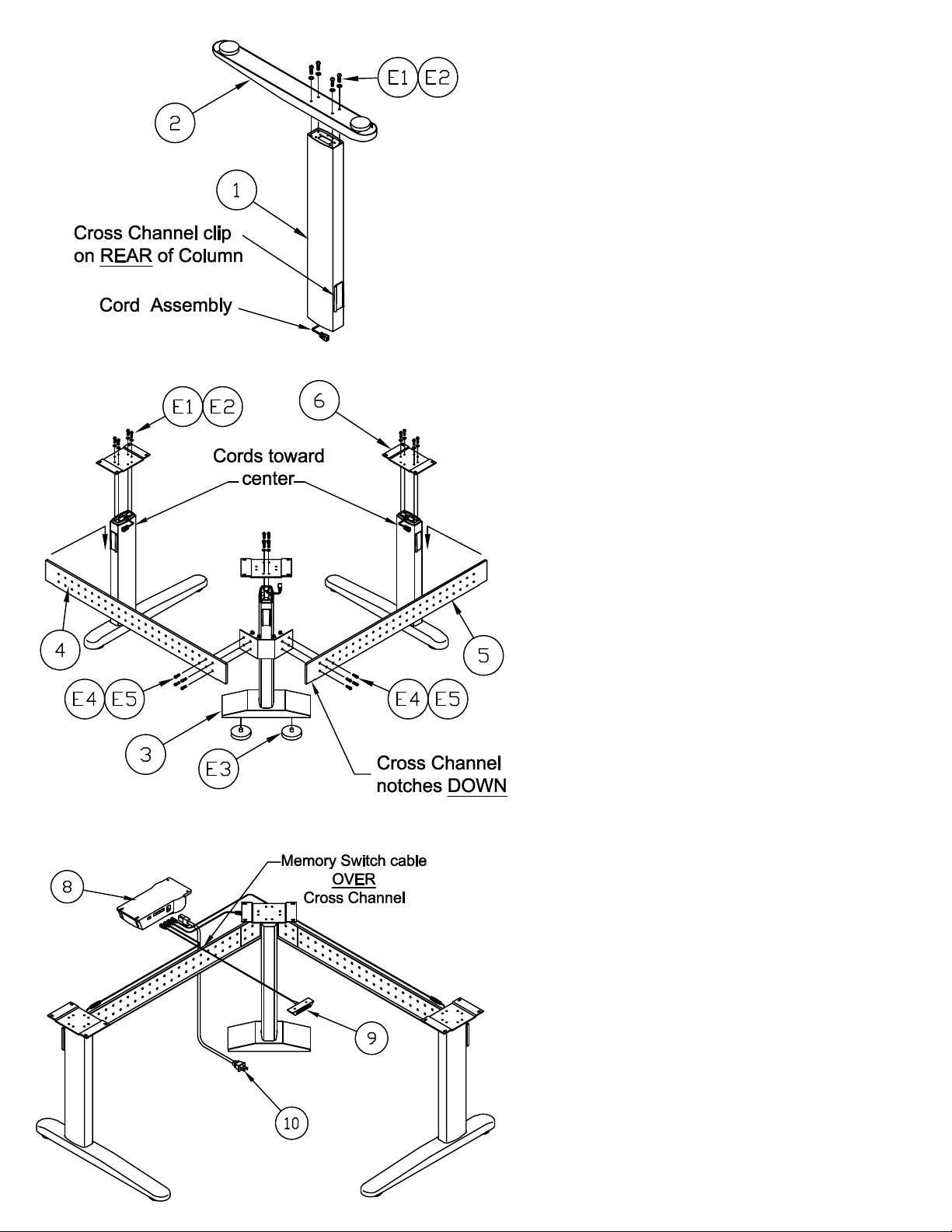
1. Place each Actuator Column Assembly (1) upside
down with the cord toward the floor. CAUTION: Do
not pinch Cord Assembly
or 3) to the Actuator Column Assembly (1) with four
Column upright and attach the Corner Bracket (7).
clip on the column. Gently tap Bracket in place with
Position the Cross Channel flange with end notches
7. Align the last 4 holes in each Cross Channel with
Corner Actuator Column and attach with four 1/4-20
8. In the event that you must reposition the Actuator
cord. Gently remove the cord and strain relief from
the notch in the top of each Column Assembly (1).
Top Plate (6) to each Actuator Column with four M6
2. Position the XR Foot or the 14" Welded Foot (2
or 3) over Actuator Column Assembly (1) with the
longer portion of the Foot toward the front (Welded
Foot is symmetrical). The Actuator column
'FRONT' is determined by the position of the cross
channel clip that is welded on each column.
Position this clip to the rear.
3. Attach the XR Foot and the 14" Welded Foot (2
M6 x 16 mm Screws (E1) and Star Washers (E2).
4. Screw the Glides (E3) into the two tapped holes
in the bottom of 14" Welded Foot (3).
5. Place the assembled 14" Welded Foot Actuator
Slide the Corner Bracket onto the tapered channel
a Rubber Mallet to assure a tight fit.
6. Place the outer Actuator column assemblies
upright and attach the Cross Channels (4 & 5).
toward the floor. Slide the Cross Channel bracket
onto the tapered channel clip on each Column.
Gently tap the Cross Channels in place with a
Rubber Mallet to assure a tight fit.
the 4 holes in the Corner Bracket mounted to the
X 1/2 Screws (E4) and 1/4-20 KEPS Nuts (E5).
Position the cords so that they are toward the
center of the assembled base. Insert the strain
relief into the appropriate Column notch. Attach
x 16 mm Screws (E1) and Star Washers (E2).
9. Attach the Memory Switch (9), Main Cord (10),
and Connector Cables (11 and 12) to the Control
Box (8).
Page 3

(3)
ATTENTION:
MAYLINE includes screws for the installation of a Work
Surface with a minimal thickness of 1 inch (25.4mm).
10. PRIOR TO ATTACHING WORKSURFACE:
Place the switch cord over the top of the Cross
Channel.
11. Align the holes in the Top with the holes in
the Mounting Plates and secure in place with
twelve #10 X 1 Screws (E7).
12. Align the holes in the Control Box (8) with the
holes in the underside of the Top and attach it
with four #10 x 3/4 Screws (E6).
13. Connect the cables to the columns. Connect
the 78.74 Cables (12) to the Outer Actuator
Columns. Connect the 39.37 Cable (11) to the
Corner Actuator Column.
14. Place the Memory Switch (9) in a
comfortable and accessible location on the
underside of the Top and attach it with two #6 x
5/8 Screws (E8).
15. Route the Actuator Column cables and the
Memory Switch cable away from moving
components and secure them in place with
Cable Clamps (E9) and Screws (E6).
Page 4

(4)
INSTRUCTIONS for
DESK SWITCH w/ PROGRAMMABLE MEMORY
321
1. Initialize system by pressing down and holding for 5 to 10
seconds after table bottoms out.
2. Push 'UP' to desired height.
3. To save this position in Memory:
A.) Press (Set)
B.) Press (do not hold) button , , or
Position is now saved under the number chosen.
4. To change to different height, press or .
This position may be saved by repeating Step 3 and using
one of the other buttons or using the same button to change
the previous setting. Up to 3 positions may be stored.
S
1
2 3
S
5. To go to new height position, press or , or press stored
height under , , or . Unit will automatically stop at
the stored position.
21 3
 Loading...