

Page 1
ffice
l
re
o
R
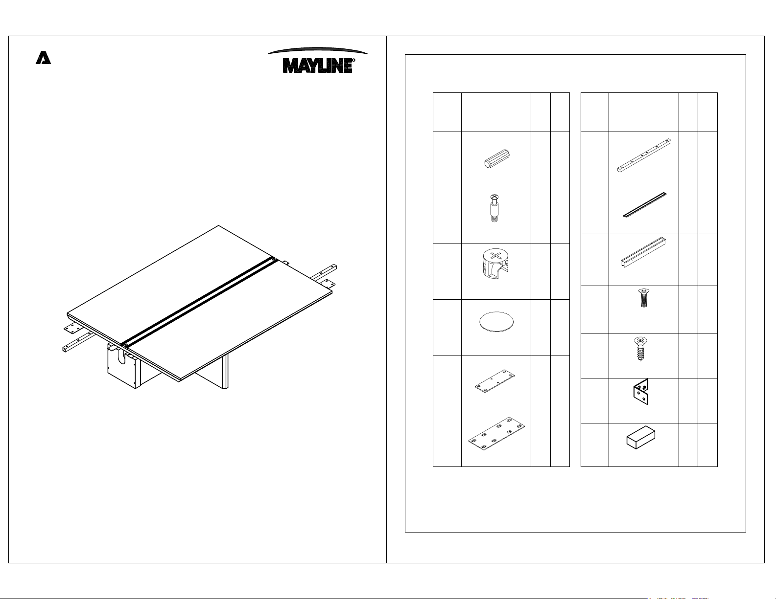
PARTS LIST
Adder Top, Support Panel and Base Leg
Model No.CMT72A
ASSEMBLY INSTRUCTIONS
CALL 1-800-822-8037 FOR ASSISTANCE
A
B
D
E
F
PartName
REALS004
Wood Dowel
REALS003
Cam Post
REALS001
Cam Fastener
REALS102
Sticker-20mm
REALS112
Mounting Plate
REALS036
Mounting Plate
HB
HB
HB
HB
HB
Qty.
4
28
28C
28
2
2
Spare
Qty
1
2
2
2
Name Part
G
REALS113
Support Bar
H
REALS114
Cable Grommet
I
REALS115
Cable Trough
J
REALS043
M6 x 15mm
K
REALS005
4mm x 16mm
P
REALS088
Angle Bracket
W
D
R
A
H
CMT72AHB
Spare
Qty.
Qty
2
1
2
28 3
5
58
8 1
E
R
A
P/N CMT72A REV04 08/14
www.mayline.com
Items with HB are in hardware box.
**Denotes Color Code
1
Page 2
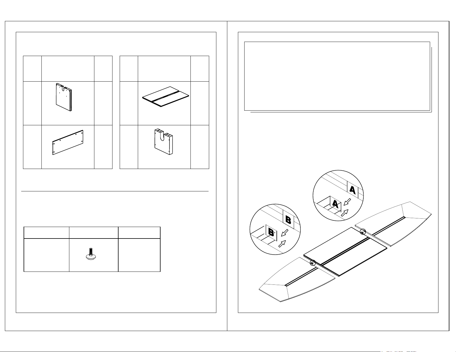
PARTS LIST
IMPORTANT!
PartName Name Part
L
CMTL**
Center Leg
M
CMT72AMP**
Modesty Panels
Qty.
1
4
Qty.
N
CMT72AT**
Top
O 1
CMT72AO**
Connection Block
1
Pre-Assembled Replacement Part List
Replacement #
Part
Qty.
Review ALL instructions before beginning assembly . These
instructions are provided to avoid problems that may occur from
improper assembly or installation. Mayline and/or its distributor
are not responsible for failure resulting from improper assembly
or installation of this product. Moreover, all warranties are void
for failure to follow these assembly instructions.
NOTE:
To assure the table sections are placed in the
proper position, please align each section with its
corresponding letter as detailed below.
REALS067
Leveler w / Insert
**Denotes Color Code
2
1
3
Page 3

1
3
2
A
B
C
K
E
M
O
L
M
C
O
B
D
B
NOTE:Assemble table legs and attach
top as shown, DO NOT assemble upside
P
down adn flip over.
4
K
O
NOTE:
From CMT72S or 84S
NOTE:
From CMT72S or 84S
4
CMT72S or 84S
5
Page 4

5
6
H
N
7
C
K
I
J
G
E
F
J
NOTE:Top Shown
Upside Down
For Clarity Only.
6
CMT72S or 84S
7
Page 5

Real Office Care Instructions
Finish Color Matching
Proper Care of Wood Surfaces
With proper care of the wood surfaces and finishes, your office furniture will
provide elegance and convenience for years. Please reference these easy-to-follow
guidelines whenever you have a question.
•
Clean all surfaces frequently with a soft cloth dampened with warm water,
moving the cloth with the grain.
or any wax or oil base products.) Never use paper towel.
•
Immediately remove any liquids that come in contact with wood surfaces
with a blotting action.
•
Lift objects to move them, never pull them across the finished surface.
•
Avoid exposure of furniture to extremes of heat and cold, or to wide
humidity variances.
•
For an additional safeguard, use a protective desk pad. This single item
could ensure a lasting finish by protecting your furniture from possible
damage caused by pens and sharp objects.
•
Do not leave plastic, vinyl or rubber items on finished wood surfaces.
Sustained contact may cause deterioration of the finish due to possible
chemical reaction between the plastic, vinyl or rubber and the catalyzed
lacquer finish.
•
If using a protective glass top, place spacer pads under the glass top to allow
the wood to breathe.
•
Avoid exposure of furniture to strong sunlight. The wood underneath the
finish may change color from prolonged exposure to sunlight.
•
Avoid exposure of furniture to harsh solvents (nail polish remover, acetates,
etc.), as it will cause finish deterioration.
(Do not use furniture polish, solvents
If you have any additional questions please contact our
customer service department at 1-800-822-8037
o
re l
ffice
8
www.mayline.com
 Loading...