

Page 1
(1)
P/N
REV 03 11/07/2012
ASSEMBLY INSTRUCTIONS
T-MATE TABLES
NOTE: Please count and inspect all pieces before disposing of any carton or packing materials.
When ordering components, specific color and/or size information may be required.
Contact a Mayline Customer Service Representative. 1-800-822-8037
** Denotes Color Code
~~Denotes Size
* Individual Items, Order by part number.
STARTER COMPONENTS ADDER COMPONENTS
REF# QTY. DESCRIPTION PART NO.
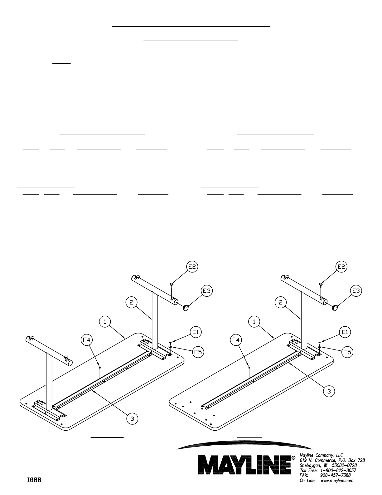
1 1 Top CALL ~~**
2 2 Leg Assembly CALL ~~**
3 1 Stiffener CALL ~~**
HARDWARE BAG
REF# QTY. DESCRIPTION PART NO.
E1 12 Screw, 1/4-20 x 3/4 700124 *
E2 4 Swivel Glide 700169 *
E3 4 End Cap 600109** / *
E4 10 Screw, #10 x 3/4" X11 *
E5 12 Washer, 9/32 x 1 x .06 W83 *
All tables utilize the same hardware bag. Depending on Model Number you may have extra hardware.
(Part No. A7936**)
REF# QTY. DESCRIPTION PART NO.
1 1 Top CALL ~~**
2 2 Leg Assembly CALL ~~**
3 1 Stiffener CALL ~~**
HARDWARE BAG
REF# QTY. DESCRIPTION PART NO.
E1 6 Screw, 1/4-20 x 3/4 700124 *
E2 2 Swivel Glide 700169 *
E3 2 End Cap 600109** / *
E4 10 Screw, #10 x 3/4" X11 *
E5 6 Washer, 9/32 x 1 x .06 W83 *
(Part No. A7937**)
STARTER
ADDER
Page 2
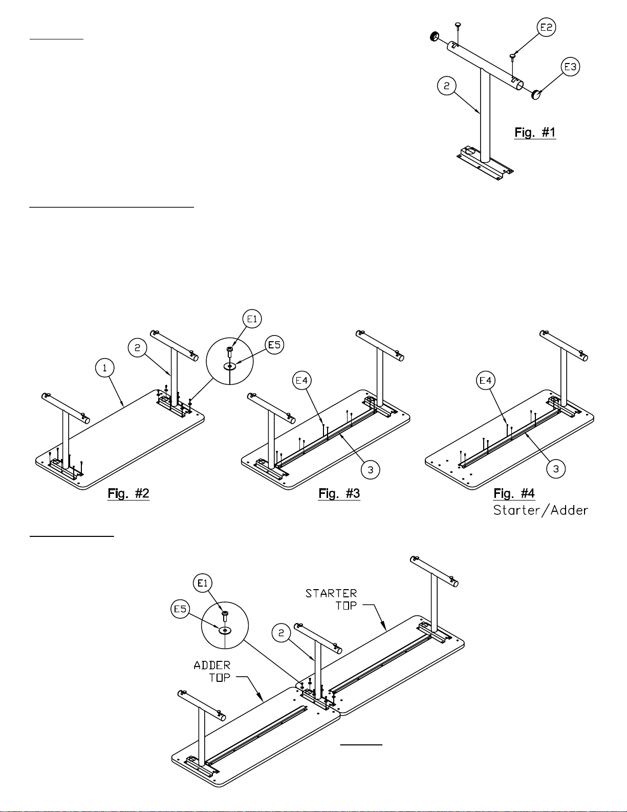
5. Attach Leg (2) onto Starter/Adder Top using three Screws (E1) & three Washers (E5) for each top. See Fig #5
Assembly:
2. Begin Assembly by determining if the table will be a stand alone unit or if there will be other tables attached. If
1. Assemble Glides (E2) into inner most threaded holes in Leg (2).
Install End Caps (E3) into Leg (2).
Stand Alone & Starter Assembly
stand alone unit is chosen see Fig. #2 & #3. If Starter/Adder Assembly is chosen see Fig. #2 & #4.
3. Place Top (1) face down on a clean flat surface. Attach Leg Assembly (2) onto Top using six Screws (E1) &
six Washers (E5) per Leg.
4. Attach Stiffener (3) using Screws (E4) as shown in Fig. #3 & #4. NOTE: Stiffeners are included on tables
larger than 48".
Adder Assembly
Fig. #5
(2)
Page 3

Stand Alone & Starter Assembly (Transition Table)
6. Begin Assembly by determining if the table will be a stand alone unit or if there will be other tables attached. If
8. Attach Leg (2) onto Starter/Adder Top using three Screws (E1) & three Washers (E5) for each top. See Fig #7
stand alone unit is chosen see Fig. #6, Step #7. If Starter/Adder Assembly is chosen see Fig. #7, Step #6.
7. Place Top (1) face down on a clean flat surface. Attach Legs (2) onto Top using six Screws (E1) & six
Washers (E5) per Leg.
WARNING
Levelers are to accommodate uneven floors. However, tables with Levelers MUST NOT be pushed,
pulled or anyway slid along the floor. ALWAYS REMOVE any items on the table and LIFT the table off
the floor while moving.
Extra inserts on the underside of the top are for optional ganging kit 10GA & Pie connectors.
(3)
 Loading...