

Page 1
ASSEMBLY INSTRUCTIONS
TechWorks Corner Tables
NOTE: Please count and inspect all pieces before disposing of any carton or packing materials.
COMPONENTS:
REF. # QTY. DESCRIPTION PART No.
1 1 TOP CALL~~**
2 2 SPREADER CALL~~**
3 2 UPPER LEG ASSEMBLY A7104**
4 2 LOWER LEG ASSEMBLY A7603**
5 1 UPPER CORNER LEG A7134**
6 1 LOWER CORNER LEG A7135**
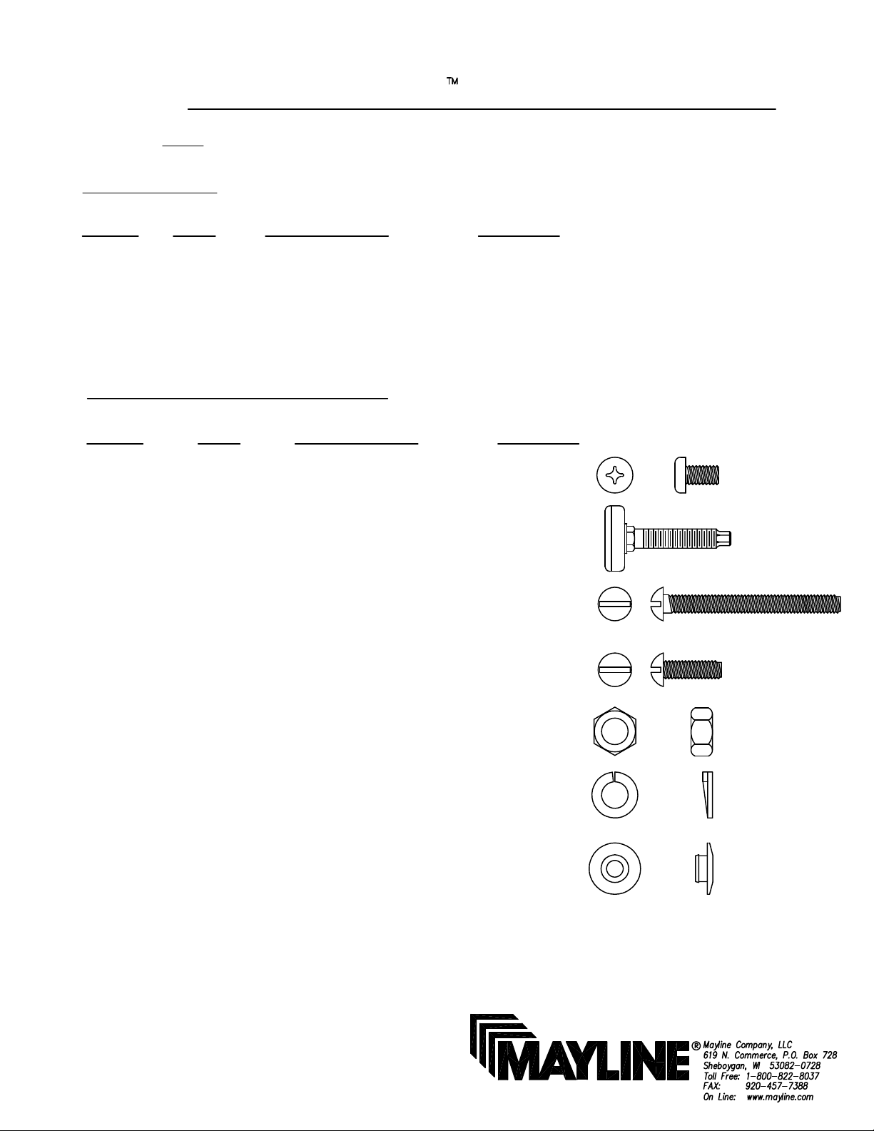
HARDWARE BAG (PART No. A7163) *for individual item, order that part number
REF. # QTY. DESCRIPTION PART No.
E1 18 1/4-20 X 1/2 SCREW X352*
E2 5 GLIDE Q588*
When ordering components, specific color and/or size information may be required.
Contact a Mayline Customer Service Representative. 1-800-822-8037
** Denotes Color Code
~~Denotes Size
E3 12 5/16-18 X 3 1/2 SCREW X241*
E4 8 5/16-18 X 3/4 SCREW X410*
E5 20 5/16-18 HEX NUT T130*
E6 20 LOCK WASHER W77*
E7 4 HOLE PLUG F639*
(1)
BETTER FOR YOUR BUSINESS
Page 2
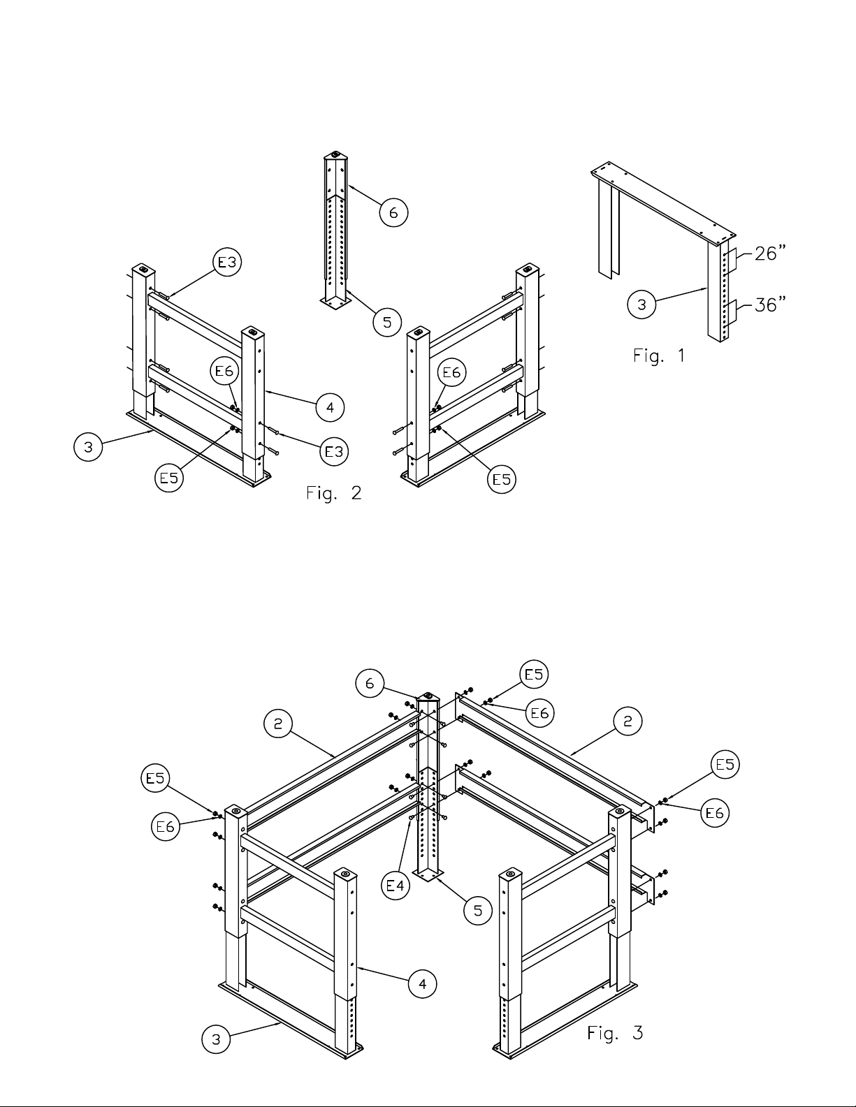
1. Select height for table using the holes in the Upper Leg (3). See Fig.1
2. Insert Screws (E3) through Upper Leg (3) and Lower Leg (4) at desired
position (12x). Secure using four Lock Washers (E6) and four Hex Nuts
(E5) where shown. See Fig 2. Do not tighten hardware at this time.
3. Assemble Spreaders (2) and Leg Assembly (3 & 4) and secure using Lock Washers (E6)
and Nuts (E5). See Fig. 3
4. Assemble Corner Upper Leg (5), Corner Lower Leg (6) and Spreaders (2) at the same
height as the Leg Assembly (3 & 4) using Screws (E4), Lock Washers (E6) and Nuts (E5). Do
not tighten hardware at this time.
(2)
Page 3

5. Place Top (1) upside-down. Place Leg Assembly onto Top. Align
holes in Leg Assembly with inserts in Top. See Fig. 4
6. Attach Leg Assembly to Top using Screws (E1).
7. Screw Glides (E2) into threaded holes on Lower Legs.
8. Tighten all hardware.
9. Flip table.
10. Insert Hole Plugs (E6)
into front of table legs (4x).
(3)
 Loading...