

Page 1
Kwik-File, LLC
Mailflow-To-Go
TB60 Work Table and SLF60 Shelf
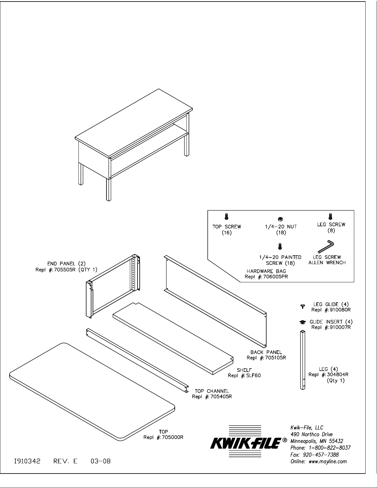
Work Table (shown with shelf), 60"W x 39"D x 29" - 36"H
Parts list and drawings for Work Table (shown with shelf)
TM
Page 2
Tool required: a blade screwdriver (allen wrench provided).
1. Unpack carton(s) and identify all parts.
2. Place table top upside down (screw holes up) on a clean, flat, smooth surface.
3. Assemble back panel, two end panels, and front support rail; it is easiest to do this with these
parts upside down on the table top.
FRONT
a. Bolt together back panel and two end panels with six painted matching
screws and Kepsnuts
(three on each side). (if you ordered the TBS60 table with shelf, omit the
one screw on each
side farthest away front the top at this time).
b. Bolt together front support rail with open flange facing inside with angled
side against top; use
four painted matching screws and Kepsnuts (two on each side).
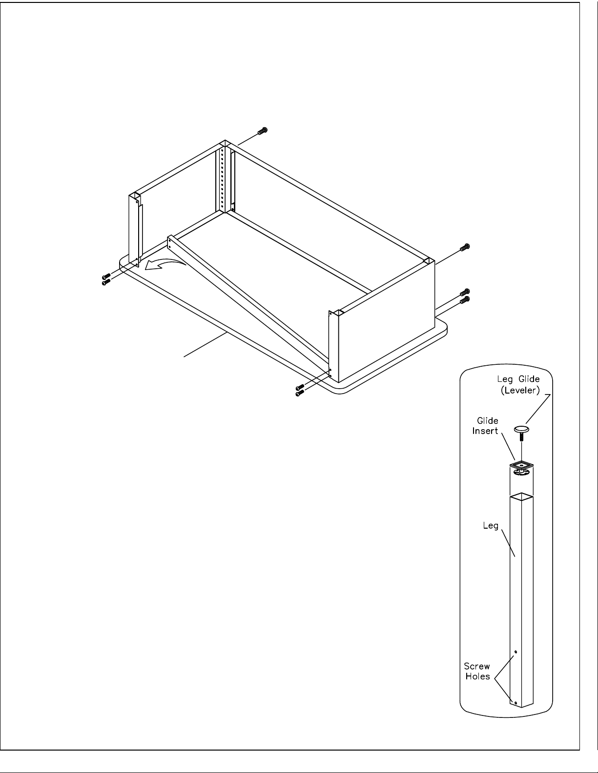
4. Locate the assembled table frame so that the 10 holes in the end and back
panel flanges line up with the 10 pre drilled holes in the top. Insert the sheet
metal screws provided through the holes and tighten into the top. Additional top
screws are self tapping and can be installed without pre-drilling.
5. Using a hammer or rubber mallet, pound the glide insert into the leg. Then
screw the leg glide into the glide insert. Place legs into the leg sleeves at the
corners of the table. Each leg has two threaded holes at the upper end; legs
should be inserted so that the holes line up with the adjustment holes in the leg
socket. Table height can be adjusted between 29" and 36" in one inch
increments.
Page 3

Table Height Max. 36"
Table Height
Adjustment
Range 29" to 36" in
One Inch Increments
Table Height Min. 29"
6. After deciding on table height, line up the threaded holes in each leg with the proper holes in the
leg sleeve; use two socket-head screws to assemble the leg in place (allen wrench provided)
7. Once all four legs have been assembled in place, carefully set table upright in place (be sure to
get help from another person).
8. Each leg has an adjustable glide. If the table needs to be leveled, turn the glide as needed to
shorten of lengthen any leg. While not essential, a carpenter's level may be helpful.
9. If you ordered the SLF60 Shelf, install it now as follows:
a. The shelf is made of (2) pieces (half shelves) which slide next to each other, flange side down.
The half - shelves are supported by the flanges at the bottom of the table end and back
panels.
b. Each half - shelf has one side with two notched corners; this side should be placed towards
the outside of the table (notches provide space for table legs).
c. Before installing the two half - shelves in place, check to make sure the two screws at the
bottom of the back of the table have been removed.
d. Carefully put the two half - shelves in place, first one, then the other. They should now be
next to each other, resting on the flanges at the bottom of the back and side panels.
e. Insert four painted machine screws. Each one will go through the hole at the bottom of the
table leg frame and the front corner of one of the half - shelves. Secure them with the
Kepsnuts provided.
f. Connect the two half - shelves from underneath through the bottom flanges using the three
painted machine screws and three Kepsnuts provided.
 Loading...