

Page 1
ASSEMBLY INSTRUCTIONS
TALON TILT-TOP TABLES
NOTE: Please count and inspect all pieces before disposing of any carton or packing materials.
All units consist of 2 cartons consisting of the following.
TOP CARTON
REF# QTY. DESCRIPTION PART NO.
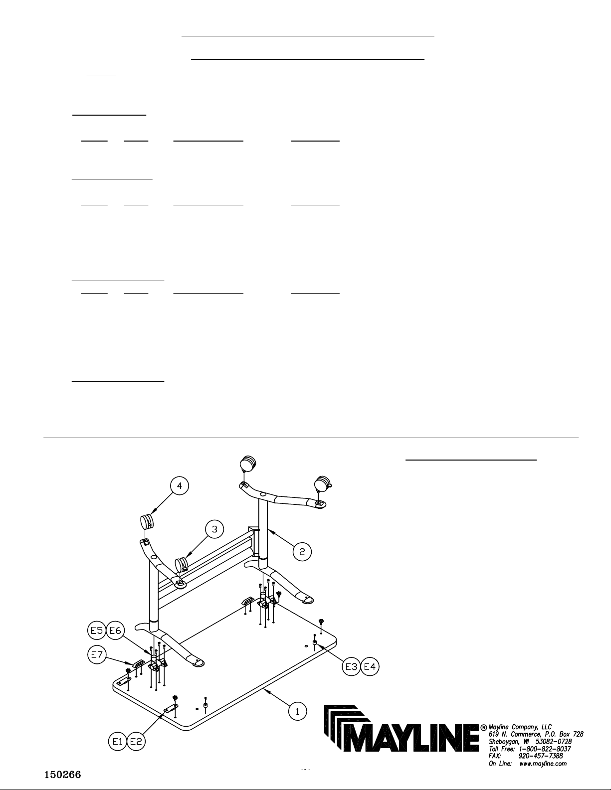
1 1 Top CALL ~~**
When ordering components, specific color and/or size information may be required.
Contact a Mayline Customer Service Representative. 1-800-822-8037
BASE CARTON
REF# QTY. DESCRIPTION PART NO.
2 1 Base Assembly CALL ~~**
3 2 Caster, Locking 8200961 *
4 2 Caster, Non-Locking 8200964 *
5 1 Caster Wrench
HARDWARE BAG (Part No. A7616 *)
REF# QTY. DESCRIPTION PART NO.
E1 2 Ganging Bracket B7523
E2 4 Knob, 1/4-20 K37
E3 2 Bumper D10 *
E4 2 Screw, #10 x 5/8 5018217 *
E5 1 Allen Wrench
HARDWARE BAG (Part No. 8200355 *)
REF# QTY. DESCRIPTION PART NO.
E6 2 Top Mounting Brackets 8200515 *
E7 8 Screw, 1/4-20 x 3/4 700124 *
E8 2 Plastic Inserts 8200157 *
** Denotes Color Code
~~Denotes Size
* Individual Items, Order by part number.
Tools Required for Assembly
Allen Wrench 5mm or 3/16",
Allen Wrench 4mm or 5/32",
Allen Wrench 8mm or 5/16" (supplied),
Caster Wrench (supplied),
Hammer,
Phillips Screwdriver.
Note: A Magnetic or Power Driver may
be used to assist in assembly.
Page 2
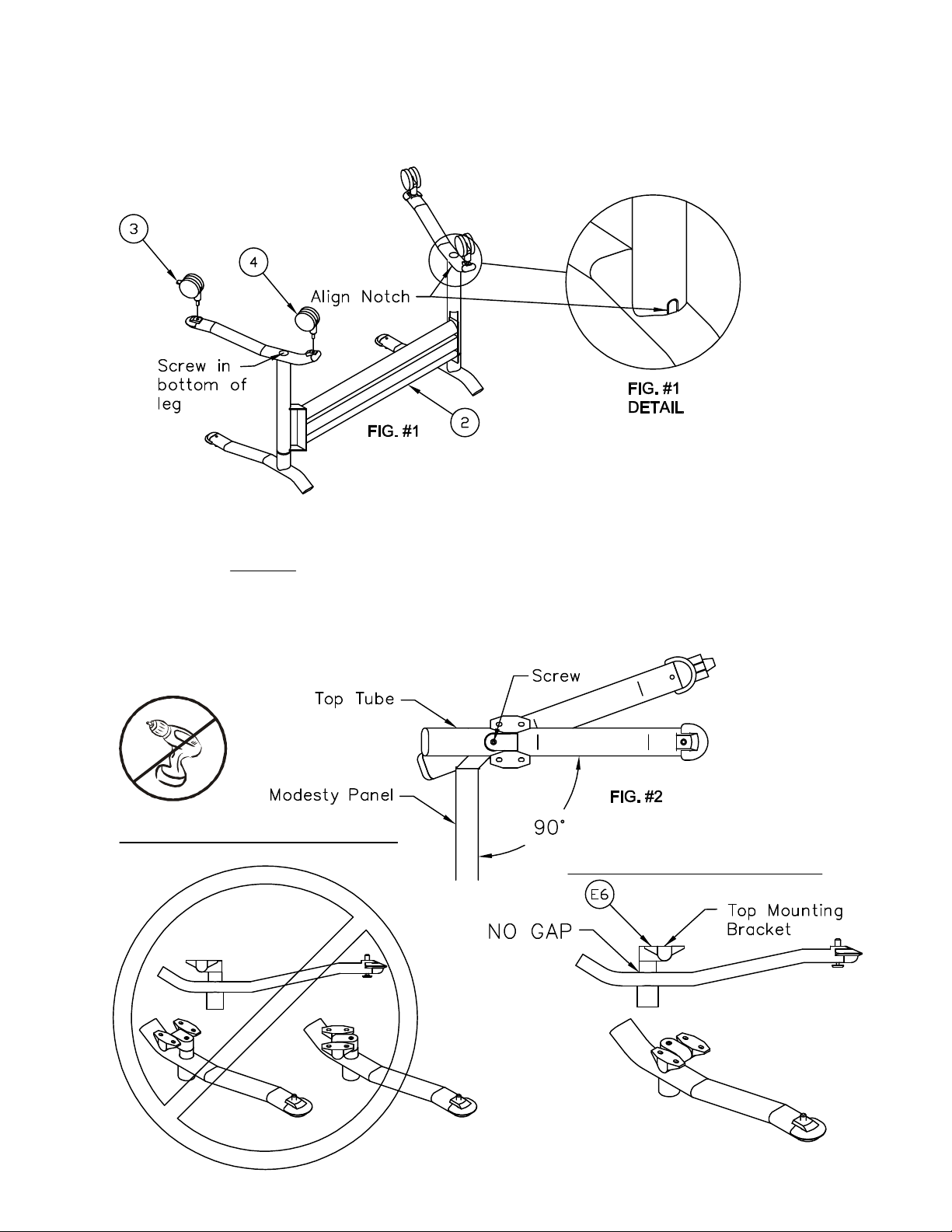
1. Begin assembly by placing the Base (2) as shown in Fig. #1. Rotate legs into place until notch aligns. See
detail in Fig. #1
2. With the supplied 8mm or 5/16" Allen Wrench tighten the screw in the bottom of the Leg. See Fig #1.
3. Attach Casters, Locking (3) & Casters, Non-Locking (4) to Base (2) as shown with supplied wrench (E5).
4. Flip Base onto casters. Rotate top tube at approximately 90° from the modesty panel as shown in Fig.
#2. Begin assembly by locating the Top Mounting Brackets (E6) and inserting them into the round leg tube
as shown in Fig. #3. Caution: Correct rotation and insertion is critical to proper operation of the unit.
5. With a 5mm or 3/16" Allen Wrench firmly tighten the screw in the top of the Top Mounting Bracket. The
compression fitting can not be over tightened by hand, however caution must be used when using a power
driver.
INCORRECT INSERTION
CORRECT INSERTION
FIG. #3
Page 3

6. Place the Top (1) face down on a clean, flat surface. Attach Plastic Inserts (E8) by aligning the stubs with
the pre-drilled holes in the top. Tap firmly with a hammer until inserts are tight against the Top. See Fig. #4
7. Position the Base Assembly as shown in Fig #5. With a 4mm or 5/32" Allen Wrench install eight Screws
(E7) through the Mounting Bracket (E6) into the metal inserts in the Top. Do Not tighten at this time. Adjust
the frame so the Locating Pin properly seats itself into the center of the locating hole in the Top. See Fig.
#5. Return to the eight Screws (E7) and tighten at this time. Caution: Over tightening may cause damage
not covered by warrantee.
FIG. #4
8. Attach Bumpers (E3) to Top by centering between Base and edge of Top in line with the arm of the Base
using Screws (E4). See Fig. #6 & #7
9. Attach Ganging Brackets with tables in upright, leveled and approximate position. Insert Knobs (E2)
through the Ganging Brackets (E1) into the metal inserts in the Top. Do not tighten Knobs at this time.
See Fig. #8
10. Rotate the Ganging Bracket (E1) under the Knob (E2). Tighten Knobs. See figure #9.
FIG. #8
Page 4

Unfolding & Nesting Instructions
1. To begin the unfolding process the unit must be in an upright position. See Fig. #10
2. Pull the Pin Assembly down and rotate the arms inward until the top tilts downward. In this
position the tables are ready for nesting. See Fig. #11
FIG. #10 FIG. #11
BASE WARRANTY PARTS IDENTIFICATION NOT INCLUDED IN ASSEMBLY
REF# QTY. DESCRIPTION PART NO.
6 2 Locating Pin Assy. 8200230M *
7 2 Top Tube Cap 2073054L *
8 2 Bottom Tube Cap 8200962 *
9 2 Bottom Tube Rear Cap 8200963 *
10 1 Central Screw 7908080286 *
11 2 Side Screw 7908080285 *
12 4 Thread Apaptor 8200965 *
* Individual Items, Order by part number.
Underside of Leg
 Loading...