

Page 1
ASSEMBLY INSTRUCTIONS
TRANSACTION SINGLE ADDER
NOTE: Please count and inspect all pieces before disposing of any carton or packing materials.
COMPONENTS:
When ordering components, specific color and/or size information may be required.
Contact a Mayline Customer Service Representative. 1-800-822-8037
Item # QTY. DESCRIPTION PART #
1 1 LEG, ADDER A8023**
2 1 BEAM ASSEMBLY Call~~**
3 1 TROUGH SIDE Call~~**
4 1 TROUGH SIDE, SINGLE Call~~**
5 1 PAN Call~~**
** Denotes Color Code
~~Denotes Size
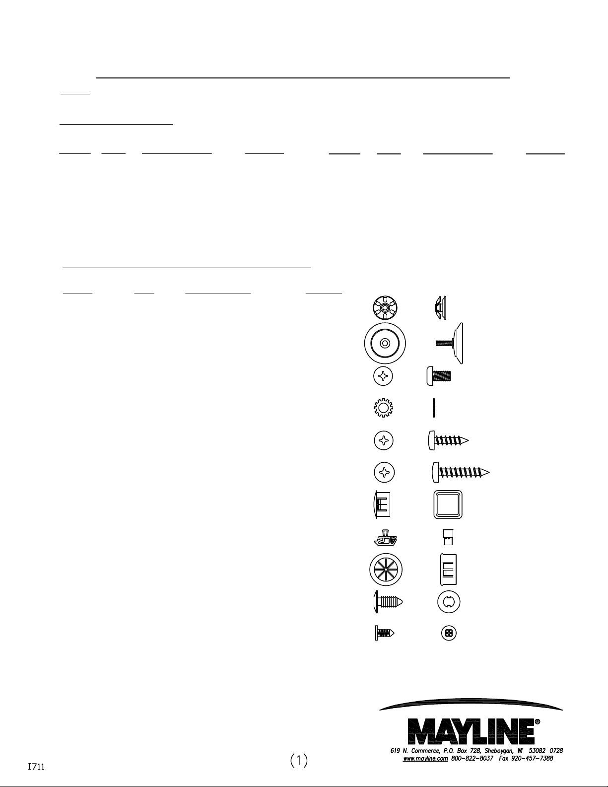
HARDWARE BAG (PART No. A8101)
Item # QTY DESCRIPTION PART #
E1 2 TUBE INSERT, 5/16-18 T139*
E2 2 GLIDE Q608*
E3 15 SCREWS #10-32 x 1/2" X204*
* for individual item, order that part number
Item # QTY. DESCRIPTION PART #
6 1 WORK SURFACE Call~~**
7 0/2/3 ACCESS PANEL Call~~**
8 2 INNER LEG PANEL B8223**
9 1 ANGLE, TOP JOINING B8224**
E4 6 WASHER, EXT STAR #10 W38*
E5 14 SCREW #10 x 3/4 X11*
E6 3 SCREW #10 x 1 X12*
E7 3 PLUG, SQUARE HOLE F782*
E8 2 SLAM LATCH Q643*
E9 1 BUSHING F764*
E10 8 PINE TREE CLIP F483*
E11 4 PINE TREE CLIP F529*
Page 2

WORK SURFACE HARDWARE
TAST48, TAST60, TAST72:
SINGLE TRANSACTION ADDER "without" ACCESS PANELS
No additional hardware is required with these products.
TAST48A
SINGLE TRANSACTION ADDER "with" ACCESS PANELS
HARDWARE BAG (PART No. A8117)
Item # QTY DESCRIPTION PART #
E12 4 ANGLE, MOUNTING B8267*
E13 9 SCREWS #10-32 x 1/2" X204*
E14 8 DOWEL PIN. PLASTIC F783*
E15 8 2" X 2" SPACER E544*
* for individual item, order that part number
TAST60A, TAST72A
SINGLE TRANSACTION ADDER "with" ACCESS PANELS
HARDWARE BAG (PART No. A8118)
* for individual item, order that part number
Item # QTY DESCRIPTION PART #
E12 6 ANGLE, MOUNTING B8267*
E13 13 SCREWS #10-32 x 1/2" X204*
E14 6 DOWEL PIN. PLASTIC F783*
E15 6 2" X 2" SPACER E544*
Page 3
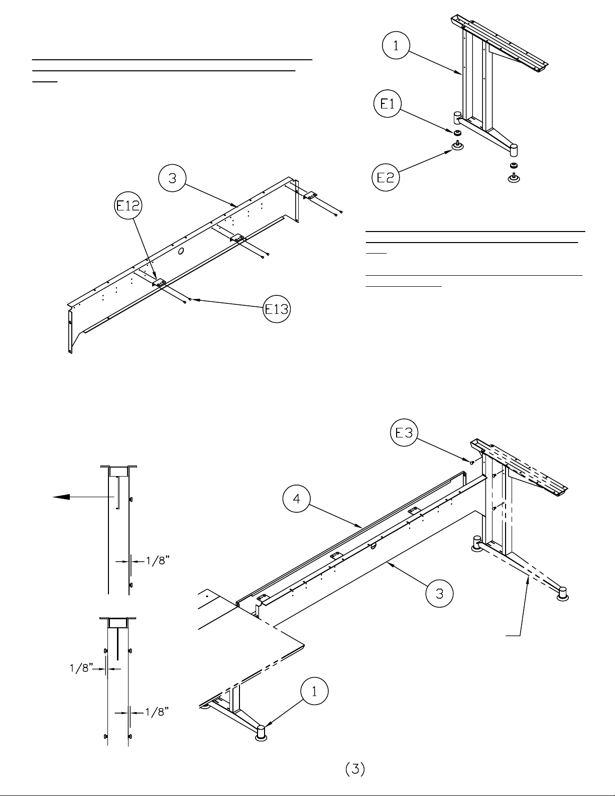
1. Install tube inserts (E1) into leg (1).
Attach mounting angles (E12) to trough side (3)
2. Screw glide (E2) into inserts.
NOTE: If the desired configuration utilizes multiple adders, substitute
an adder leg for the right hand starter leg shown in the following
steps.
NOTE: The illustrations shown here reflect a 60"W or
72"W table. If installing a 48"W, part quantities may
vary.
NOTE: If installing a table without access panels (7),
proceed to Step 4.
3.
using screws (E13).
4. Install screws (E3) to the inside of leg (the side opposite gusset
flange), leaving approximately 1/8" between screw head and leg tube.
5. Using slots in trough sides (3, 4), hook trough sides onto screw
heads on both legs. DO NOT TIGHTEN SCREWS.
GUSSET FLANGE
(Starter leg only)
RIGHT HAND STARTER LEG
OR ADDER LEG.
ADDER LEG
IF REQUIRED
Page 4

Page 5

For tables "WITHOUT" Access Panels (7).
14. Position work surface (6) without access panels and
secure with screws (E5).
For tables "WITH" Access Panels (7).
14. Insert dowels (E14) into holes in access panels (6) as
shown below. NOTE: For 48" W tables use the positions
shown in the far left and right of the view below.
15. Lay access panels (7) onto table frame so that dowels
engage holes in mounting angle.
16. Insert spacers (E15) between access panels and work
surfaces as shown (2 per access panel).
17. Position work surfaces and secure with screws (E5).
Remove spacers.
Install dowels (E14) in
the positions shown
Underside of Access Panels
Page 6
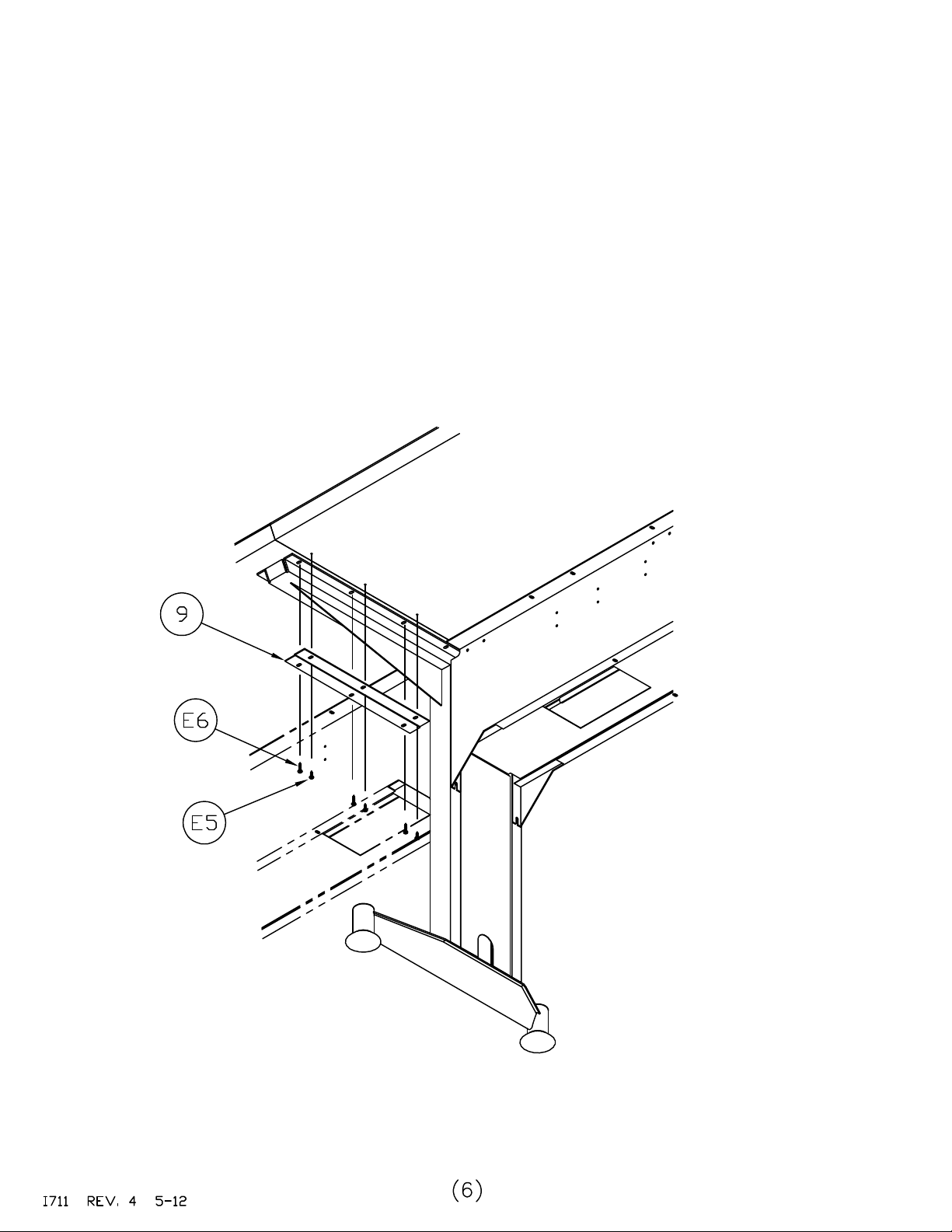
18. Remove screws (E5) from existing worksurface
and install top joining angle (9) using screws (E6).
19. Position work surface (6) and secure using
screws (E5).
 Loading...