

Page 1
INSTRUCTIONS FOR RESTRINGING ABOVE
CATALOG No.
7355100
7355300
7355A
7355B
7355C
BOARD MAYLINE STRAIGHTEDGE
NOTE: Please count and inspect all pieces before disposing of any carton or packing materials.
COMPONENTS:
REF.# QTY. DESCRIPTION PART No.
1 CALL~~ Cable Coil CALL~~
2 2 * Ring Terminal Q6
* Ring Terminal (Item 2) must be ordered separately when
buying cable in Bulk Spool
When ordering components, specific color and/or size information may be required.
Contact a Mayline Customer Service Representative. 1-800-822-8037
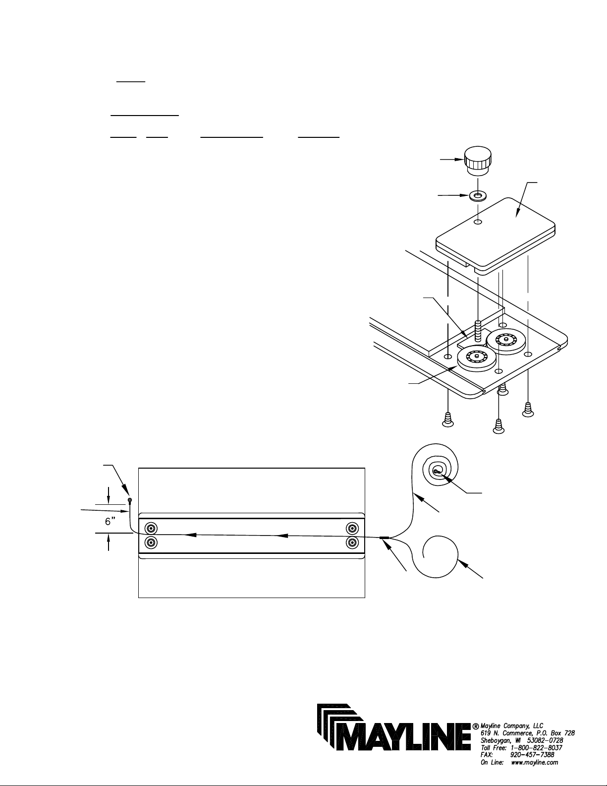
1. Remove Pulley Housing, Brake Know Washer and Brake Knob.
Repeat procedure on other end. Fig. 1
2. Remove old cable by pulling cable out of slot in Straightedge.
3. If using Bulk Cable, total cable length required: (3) x (length of
straightedge) + 8 feet.
4. Cut total cable length into two equal lengths.
5. Feed on end of Cable 1B through slot in straightedge cap until
approximately 6 inches extends through opposite end. Fig. 2
6. Tape end of Cable 1A to Cable 1B and pull through until 6
inches of Cable 1A is through opposite end. Fig. 2 Remove
tape.
Brake Knob
Brake Shoe
Ball bearing
Pulley
Fig. #1
Washer
Pulley
Housing
Ring
Terminal (2)
Cable (1B)
Fig. 2
7. Crimp ring Terminal (2) onto the upper ends of cables 1A and 1B.
8. Replace pulley housing / brake assembly. Fig. 1
Tape
Ring
Terminal (2)
Cable (1A)
Cable (1B)
(1)
Page 2
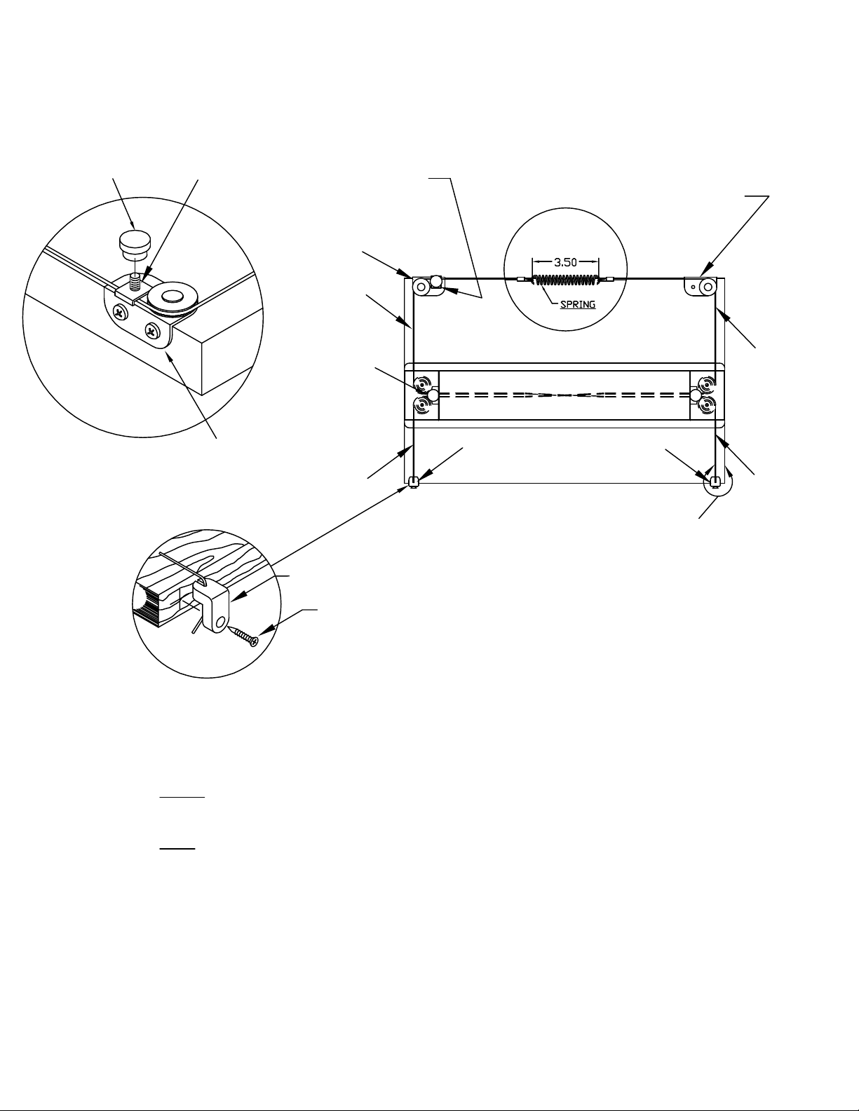
9. Attach cable ends with terminals to spring. Align cable parallel
with edge of board as shown in Fig. 3. Be sure that the cable
passes between cable clamp and L.H. Plate Assembly.
Knob
Cable Clamp
LEFT Corner
Plate
L.H. Corner
Plate Assembly
Cable (1B)
Cable Brake
Knob
Cable (1A)
Cable Clamp
R.H. Corner
Plate Assembly
Spring Length
Not to Exceed
(CENTER Spring between Plate Assemblies)
Stedge Stop
Stedge Stop
Align Cable Parallel with
edge of Board
Fig. 3
Cable (1A)
Cable (1B)
Stedge Stop
Screw
10. Insert cable through top of stop.
11. Pull cable on RIGHT side of work surface to remove slack from
this portion. Tighten Stedge Clamp Screw at this time.
12. Pull cable on LEFT side to remove slack. DO NOT Exceed
spring tension (Fig. 3). Tighten Stedge Clamp Screw at this time.
13. Excess cable can be trimmed off leaving several inches for
future adjustments.
14. Straightedge may be locked in positio by tightening Knobs
installed in Step #1 on both ends of Straightedge or left loose to
allow free movement up or down.
(2)
Page 3
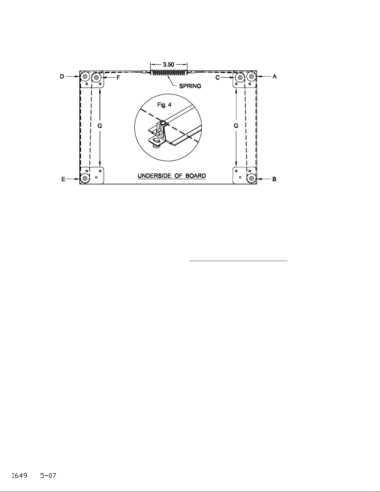
INSTRUCTIONS FOR RESTRINGING
UNDER-BOARD PARALLEL RULE
Spring Length
Not to Exceed
1. Remove old cable by loosening screw retaining cable on attachment clamp. Fig. 4
2. Crimp Ring Terminal (2) to one end of Cable (1).
3. Starting from Inside of board, thread end of cable around pulley 'A' to front of board around pulley
'B', then back around pulley 'C'. Now cross the board and thread around pulley 'D', then to front of
board around pulley 'E' and back around pulley 'F'. DO NOT TWIST OR KINK CABLE.
4. Connect Ring Terminal to Spring.
5. Slide 2nd Ring Terminal on opposite end of Cable. Hook the Terminal onto other end of spring.
Hold Ring Terminal and pull end of cable until spring is extended approximately 1/2". Crimp terminal
at this position. Be sure cable runs freely.
6. Place straightedge in position on board and fasten blade clamps (shown upside down, Fig.4) to
ends of straightedge with knurled nuts. Adjust sliding bar to correct length and tighten screws.
7. Loosen cable clamp screws on bottom of blade clamps and place cable between washer and
groove in blade clamps. Align straightedge and lamp cable by tightening cable clamp screws.
Straightedge can be removed from blade and replaced without changing alignment by simply
removing knurled nuts.
(3)
 Loading...