

Page 1
ASSEMBLY INSTRUCTIONS
BETTER FOR YOUR BUSINESS
SPLIT TOP RANGER TABLE
CATALOG No:
7772 7773
7772A 7773A
NOTE: Please count and inspect all pieces before
disposing of any carton or packing materials.
When ordering components, specific color information may be required.
Contact a Mayline Customer Service Representative. 1-800-822-8037
COMPONENTS:
** Denotes Color Code
TABLE
REF. # QTY. DESCRIPTION PART No.
1 1 R.H. END ASSEMBLY A7560**
2 1 L.H. END ASSEMBLY A7559**
3 1 FRONT RAIL B7650**
4 1 REAR RAIL B7189**
5 1 FOOT RAIL B2026**
6 1 DUST COVER L4540
7 1 'H' FRAME A4011**
8 2 SUPPORT RAIL B6543**
OPTIONAL COMPONENTS:
The following components are in addition
to the TABLE components.
TOOL DRAWER ACCESSORY:
9 1 CENTER SUPPORT B7469**
10 2 DRAWER SLIDE B6361
11 1 TOOL TRAY F187
12 1 TOOL DRAWER A7553**
** Denotes Color Code
HARDWARE BAG
Part No. A7683 Ranger
Part No. A7684 Ranger with OPTIONAL Tool Drawer
TABLE *for individual item, order that part number
REF. # QTY. DESCRIPTION PART No.
E1 2 LOWER HINGE B195*
E2 2 UPPER HINGE B194*
E3 8 10-24 x 3/8 SCREW X147*
E4 8 10-24 KEPS NUT T2*
E5 12 1/4-28 x 3/8 SCREW X156*
E6 12 1/4-28 KEPS NUT T25*
E7 10 8 x 5/8 SCREW X140A*
E8 18 10 x 3/4 SCREW X11*
E9 2 BUMPER D10*
E10 2 LIFT ASSEMBLY V120A*
E11 4 10-32 x 1/2 FLAT HEAD SCREW X191*
E12 10 10-32 x 1/2 PAN HEAD SCREW X204*
OPTIONAL COMPONENTS HARDWARE:
The following hardware is in addition to the
Table Hardware .
TOOL DRAWER ACCESSORY:
E13 6 10-24 x 3/8 SCREW X147*
E14 4 10-24 KEPS NUT T2*
E15 1 HANDLE Q35*
E16 6 8-32 x 3/8 THRD. CUTTING SCREW X247*
E17 6 8-32 x 5/16 MACHINE SCREW X384*
E18 6 8-32 ACORN NUT T129*
(1)
Page 2
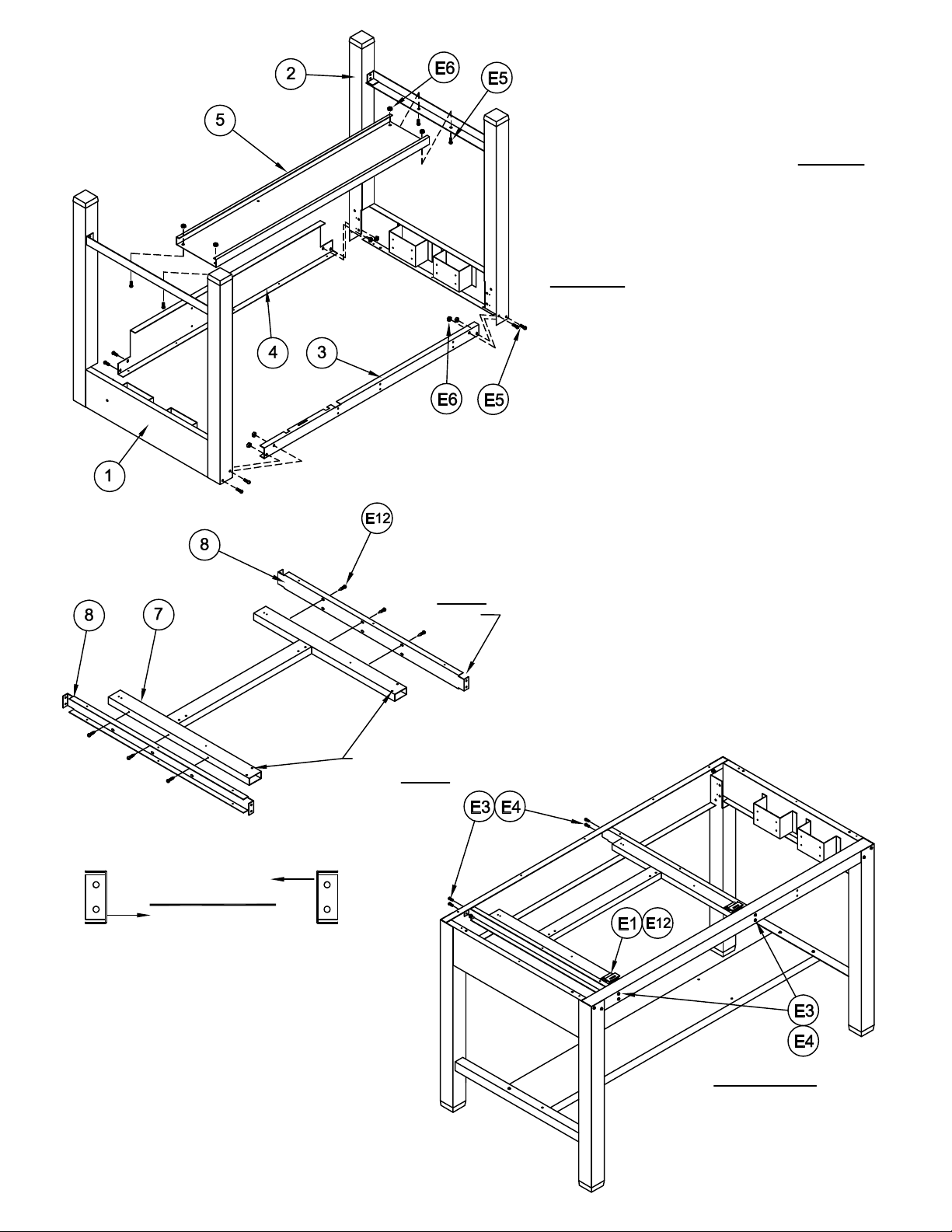
1. Place the two End Assemblies (1 & 2) upside.
Assemblies with four Screws (E5) and Nuts (E6).
Position the Front Rail (3) with notches 'UP'.
Position the Rear Rail (4) with the Dust Cover
attachment holes toward the floor. Secure these
Rails to the End Assemblies with two Screws
(E5) and two Nuts (E6) per end. DO NOT
tighten screws at this time.
2. Position the Foot Rail (5) with flat surface
toward the floor. Attach the Foot Rail to the End
TIGHTEN all rail attaching screws now.
3. Turn assembled table to an upright position.
MAYLINE recommends that two people perform
this task.
4. Attach the Support Channels (8) to the 'H'
Frame (7) using #10-32 x 1/2 Screws (E12).
Position the Frame with the diagonal holes for
the top hinge attachment to the front. Position
each Support Channel with the 7/8 notch to the
front. Frame should be flush with the top of the
Support.
Right Support
CHANNEL FACE
Left Support
CHANNEL FACE
Smaller (7/8) NOTCH
toward FRONT
all Supports
Diagonal holes
toward FRONT
5. Place the 'H' Frame/Support Assembly into
position and attach it to the Front and Rear Rails
using #10-24 x 3/8 Screw (E3) and KEPS Nuts
(E4).
6. Attach Lower Hinge (E1) to 'H' frame with
#10-32 x 1/2 Thread Cutting Screw (E12).
Position with hinge slot toward front of table.
FRONT of TABLE
(2)
Page 3

7. Attach the Upper Hinges (E2) to the underside of
the Tilt Top with #10 x 3/4 Particle Board Screws
8. Attach Lift Assembly (E10) to the 'H' Frame cross
Raise the Lift Assembly and align the holes in the lift
10. Attach the Reference Top to the base with #10 x
3/4 Particle Board Screws (E8) through the front and
12. Attach top Bumpers (E9) to Dust Cover with #10
x 3/4 Screw (E8). Position approximately as show.
(E8). Position with the hinge tab toward the front
edge of the top.
rail with #10-32 x 1/2 Flat Head Screws (E11).
9. Install the Tilt Top onto the table. Insert the
upper hinge tab into the slot of the lower hinge.
FRONT of TABLE
FRONT
Tab toward front edge
with the holes in the top. Attach with #10 x 3/4
Particle Board Screws (E8).
rear rail and through the side flange.
11. Attach Dust Cover (6) to base with #8 x 5/8
Screws (E7).
Measured from edge of dust cover.
FRONT of TABLE
(3)
Page 4

1. Separate the Drawer Slides (10) into two pieces. Extend the
Slide to the full extension. Remove the smaller portion (10B) by
pressing the plastic release and pulling.
2. Attach the large Slide portion (10A) to the Center Support (9)
using two Screws (E16). Begin attaching the Slide using the large
'Horizontal' slot in the last mounting tab.
3. Attach one large Slide portion (10A) to the brackets on the R.H.
side of the table using two Screws (E16). Begin attaching the
Slide using the large 'Horizontal' slot in the last mounting tab.
4. Attach the smaller Slide portion (10B) to each side of the
Drawer body using three Screws (E17) and three Acorn Nuts
(E18). Begin attaching the Slide using the 'Vertical' slot in the first
hole cluster.
5. Install the Handle (E15) onto the Tool Drawer head using
Screws (E13).
6. Install the assembled Center Support into the Base. Attach the
Support with two Screws (E13) and two Nuts (E14) per rail.
7. Install the drawer into the assembled table.
(4)
 Loading...