

Page 1
(1)
ASSEMBLY INSTRUCTIONS
RANGER STEEL FOUR-POST TABLES
with LIGHT TOP
CATALOG No.
7734BLT
7736BLT
NOTE: Please count and inspect all pieces before disposing of any carton or packing materials.
When ordering components, specific color and/or size
information may be required. Contact a Mayline
Customer Service Representative. 1-800-822-8037
COMPONENTS:
REF. # QTY. DESCRIPTION PART No.
1 1 R.H. END ASSEMBLY A7558**
2 1 L.H. END ASSEMBLY A7757**
3 1 FRONT RAIL CALL~~**
4 1 REAR RAIL CALL~~**
5 1 FOOT RAIL CALL~~**
6 1 DUST COVER CALL~~
7 2 TILT ROD ASSEMBLY A315
8 1 CENTER SUPPORT B7469**
9 4 DRAWER SLIDE B6361
10 1 TOOL TRAY F187
11 1 TOOL DRAWER A7553**
12 1 SHALLOW DRAWER CALL~~**
AUXILIARY DRAWER UNIT ACCESSORY:
All components are included with the Drawer Unit.
TABLE
** Denotes Color Code
~~Denotes Size
*for individual item, order that part number
HARDWARE BAG (PART No. A7682)
REF. # QTY. DESCRIPTION PART No.
E1 2 LOWER HINGE B195*
E2 2 UPPER HINGE B194*
E3 10 #10-24 x 3/8 SCREW X147*
E4 8 #10-24 KEPS NUT T2*
E5 12 1/4-28 x 3/8 SCREW X156*
E6 12 1/4-28 KEPS NUT T25*
E7 11 #8 x 5/8 SCREW X140A*
E8 2 RUBBER BUMPER D38*
E9 2 KNOB K13*
E10 2 WASHER W30*
E11 2 5/16-18 x 1/2 BOLT X157*
E12 2 TILT ROD GUIDE B160*
E13 1 DRAWER HANDLE Q35*
E14 8 #8-32 x 3/8 THRD. CUTTING SCREW X247*
E15 12 #8-32 x 5/16 MACHINE SCREW X384*
E16 12 #8-32 ACORN NUT T129*
E17 2 TILT ROD SPRING V95*
AUXILIARY DRAWER UNIT ACCESSORY:
All hardware is included with the Drawer Unit.
TABLE
FOR LIGHT TOP INSTALLATION REFER TO
INSTRUCTIONS INCLUDED WITH THE TOP
Page 2
(2)
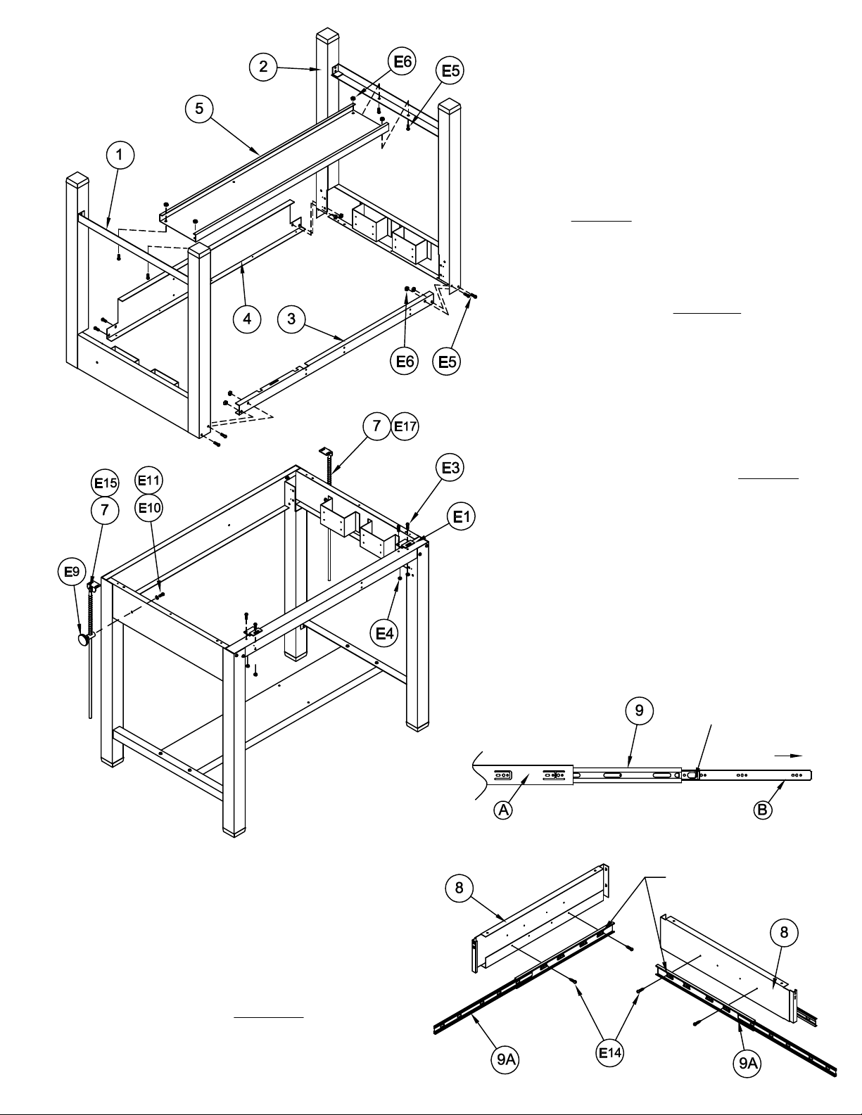
1. Place the two End Assemblies (1 & 2)
with two Screws (E5) and two Nuts (E6) per
Rail to the End Assemblies with four Screws
4. Fasten one Tilt Rod Guide (E12) to each
5. Insert Tilt Rod Assembly (7) through the
upside. Position the Front Rail (3) with the
larger of the two flanges toward the floor.
Position the Rear Rail (4) with the Dust
Cover attachment holes toward the floor.
Secure these Rails to the End Assemblies
end. DO NOT tighten screws at this time.
2. Position the Foot Rail (5) with flat
surface toward the floor. Attach the Foot
(E5) and Nuts (E6). TIGHTEN all rail
attaching screws now.
3. Turn assembled table to an upright
position. MAYLINE recommends that two
people perform this task.
side of the table using one Bolt (E11) and
one Washer (E10) per guide. DO NOT
tighten completely.
6. Separate the Drawer Slides (9) into two pieces.
Extend the Slide to the full extension. Remove the
smaller portion (9B) by pressing the plastic release
and pulling.
Spring (E17). Insert the Rod and Spring
through the hole in Guide and tighten in
place with Plastic Knob (E9).
PRESS
PULL
Start "HERE"
7. Attach the large Slide portion (9A) to the Center
Support (8) using two Screws (E14). Begin attaching
the Slide using the large 'Horizontal' slot in the last
mounting tab. Repeat this procedure on the opposite
side of the Center Support.
TOOL
DRAWER
SLIDE
SHALLOW
DRAWER
SLIDE
Page 3

(3)
8. Attach one large Slide portion (9A) to the
brackets on the R.H. side of the table using two
Screws (E14). Repeat this procedure on the L.H.
side of the Table.
9. Attach the smaller Slide portion (9B) to each
side of the Drawer body using three Screws (E15)
and three Acorn Nuts (E16). Repeat this
procedure for the Shallow drawer.
10. Install the Drawer Pull (E13) onto the Tool
Drawer head using Screws (E3).
11. Install the assembled Center Support into the
Base. Attach the Support with two Screws (E3)
and two Nuts (E4) per rail.
12. Install the drawers into the assembled table.
13. Lay the Dust Cover (6) onto the table. Align
the holes in the Dust Cover with the holes in the
Rails and attach with Screw (E7).
 Loading...