

Page 1
P/N
REV 02 05/10/12
(1)
ASSEMBLY INSTRUCTIONS
PIE CONNECTOR TABLES
NOTE: Please count and inspect all pieces before disposing of any carton or packing materials.
COMPONENTS
REF# QTY. DESCRIPTION PART NO.
1 1 Top CALL ~~**
HARDWARE BAG
REF# QTY. DESCRIPTION PART NO.
E1 4 Bracket, Ganging B8099 *
E2 4 Knob 1/4-20 x 1/2 K37 *
E3 20 Screw #10 x 3/4 X11 *
When ordering components, specific color and/or size information may be required.
Contact a Mayline Customer Service Representative. 1-800-822-8037
(Part No. A7935 *)
** Denotes Color Code
~~Denotes Size
* Individual Items, Order by part number.
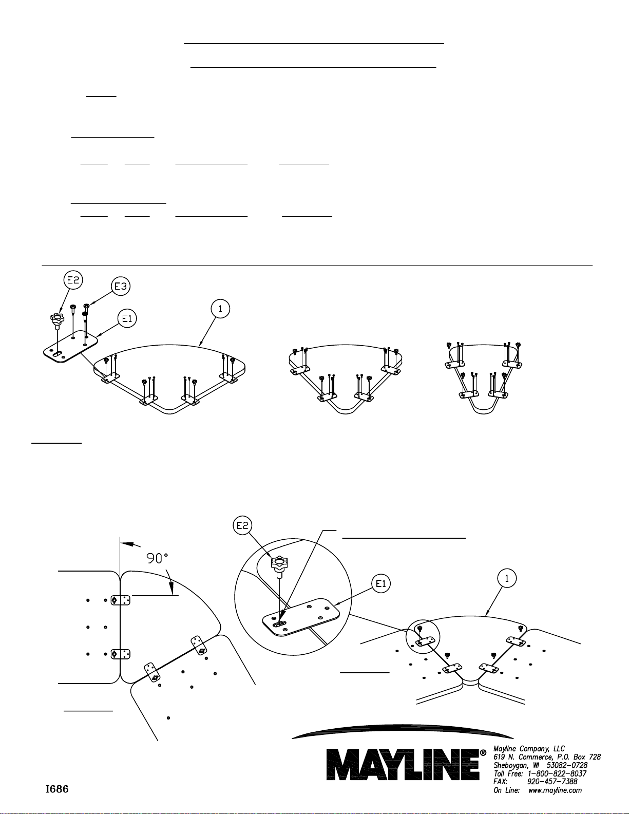
Assembly
1. Place Assembled Table face down on a clean flat surface and position the Pie Connecting table. See Fig.
#1a & 1b.
2. Attach Bracket (E1) to Assembled Top using Knobs (E2) at a 90 degree angle & centered in obround hole
(4X). See Fig. #1a & 1b.
Center obround hole.
Fig. #1b
Fig. #1a
Page 2
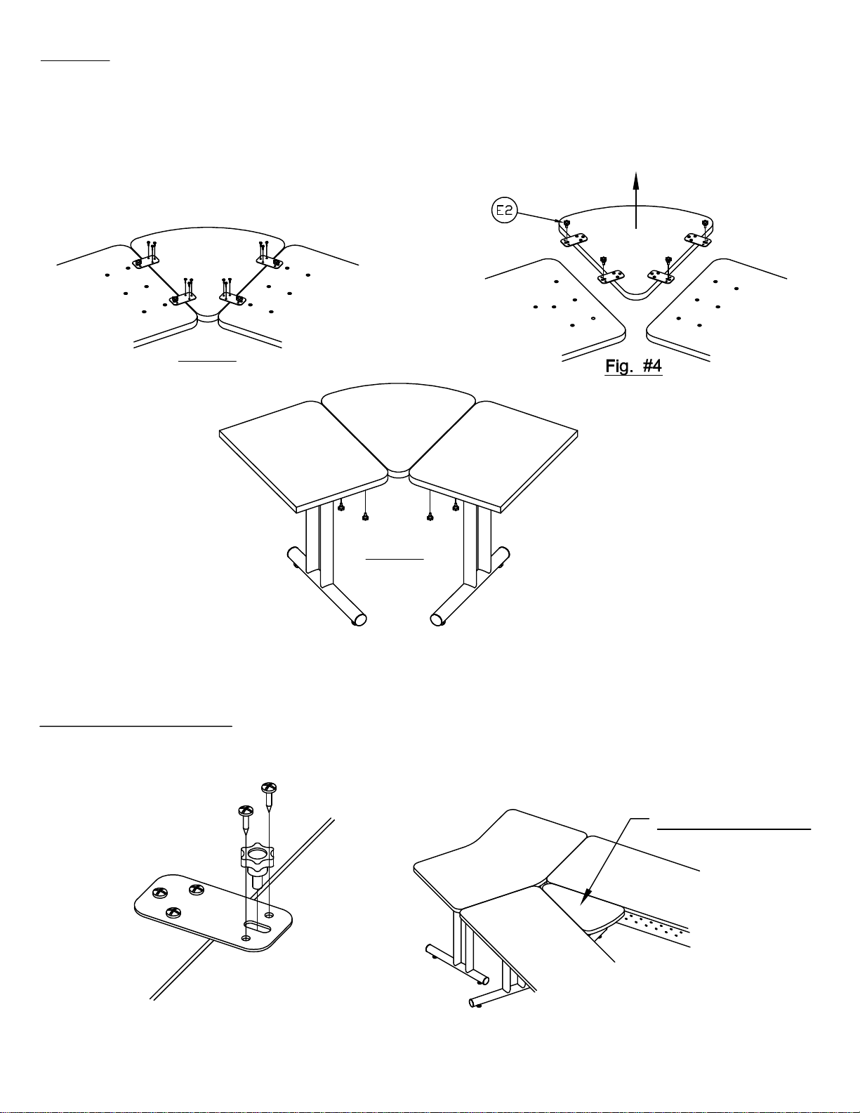
Assembly
3. Attach Pie Top (1) to Brackets (E1) using three Screws (E3) per bracket. See Fig. #3 No pilot hole necessary.
(2)
4. Remove Knobs (E1) & slide the Pie Table outward. See Fig. #4
5. Rotate Tables Right side up. Attach Knobs (E2) to Tables. See Fig. #5
Fig. #3
Fig. #5
Permanent Ganging Option
1. Extra Screws (E3) are provided for a permanent ganging solution or in a permanent conference table setting.
Conference Setting
 Loading...