

Page 1
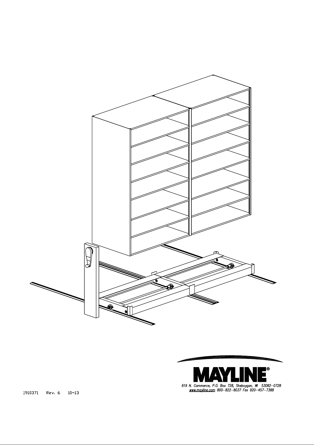
Assembly Procedures
for Mobile Lite
(1)
Page 2
MOBILE LITE SYSTEM INSTALLATION
Kwik-File recommends the removal of all carpet and padding prior to installing Mobile Lite. We suggest
that carpet be removed the length and width of each track. Product performs best when installed on
concrete or tile. NOTE: Kwik-File cannot assure proper leveling if track is installed on low-pile
carpet.
* Read all instructions before attempting assembly.
* Check floor plan layout. Measure and mark floor for intended
layout, preplan exact location of all units with regards to columns,
lights, windows and obstructions.
GENERAL NOTES:
1. Installation of the in-track anti-tip track begins with the floor plan layout . It is imperative for the
proper operation of this system that the tracks be parallel and square. On a two track system, the
in-track anti-tip is the rear track. On a three or more track system, the anti-tip track is the second (from
the front) track.
2. The carriage with the anti-tip guide is designed to be inserted into the track after the track is in the
approximate location, but prior to completely securing it to the floor. This will eliminate the need to
disassemble the guide from the carriage.
3. The carriage is shipped completely assembled, however if the anti-tip guide assembly cannot be
inserted into the track it is possible to remove and reinstall the mount assembly. Care must be taken to
properly place the mount tightly to the channel and angle of the carriage.
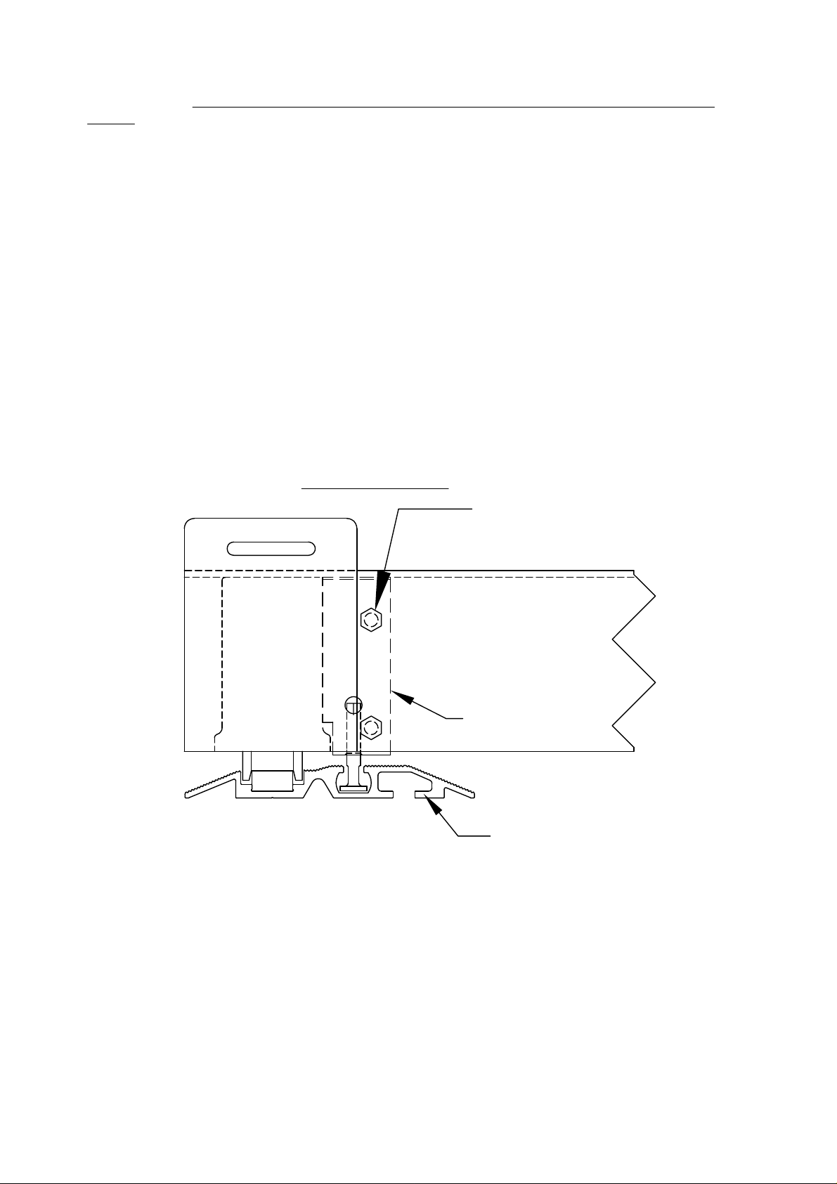
Detail of Anti-Tip Guide
4. Required tools:
- Hammer drill (cement drill bit provided)
- Drill with Phillips screw adapter
- Flat and Phillips screwdriver
- 9/16" socket
- 1-1/16" thin wall socket
- 3/4" socket
- Level
- Chalk line
- Measuring tape
- #2 Phillips driver bit
- Hammer
ATTACHED WITH (2)
1/4-20 X 3/4" BOLTS
ANTI-TIP GUIDE
MFTA TRACK
(2)
Page 3
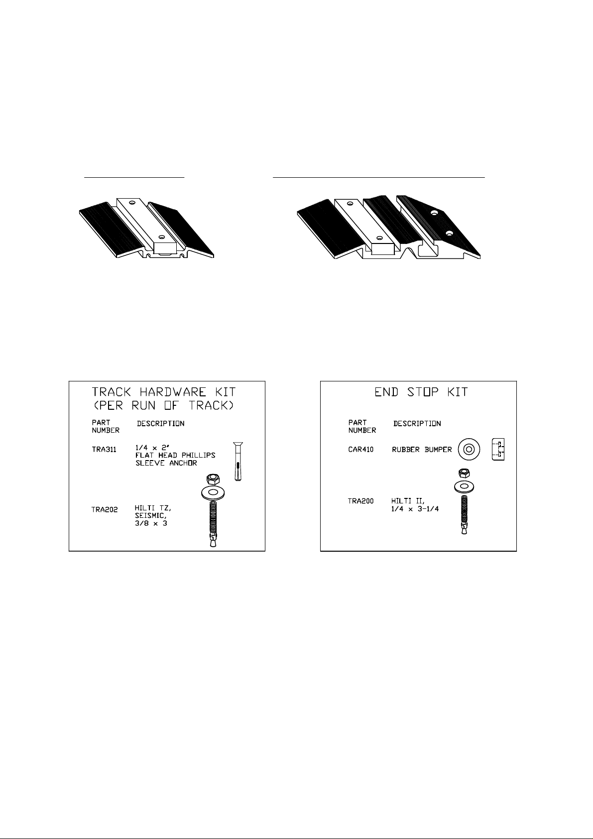
Flat Track (MFT) In-Track Anti-Tip Flat Track (MFTA)
(3)
Page 4

TRACK INSTALLATION:
STEP 1.
If included: Assemble one stationary unit at
the end of the track run per layout. Use
stationary shelving to assist in aligning track
and mobile carriage. If the stationary
shelving is installed on a fixed base you
must install the MLFANTITIP to the fixed
base.
#12 X 3/4"
TEK SCREW
HILTI TZ 3/8X3
STATIC BASE
MLFANTITIP INSTALLATION
STATIC BASE
ANCHOR BRACKET
STEP 2.
Layout all track (use carriage to affirm track
spacing by rolling carriage on loose track).
The track closest to the wall will be no less
than 1 1/2" from the rear edge of track to the
wall. On a single section carriage, the In-Track
AntI-Tip will be the rear track. On a two section
carriage, the In-Track Anti-Tip will be the
center track. Review the layout determining
where the anti-tip track will lie. Position the
track in place.
SAMPLE LAYOUT:
STEP 3.
Verify you will end up with 1 1/2" wall clearance
on the track run when system complete.
STEP 4.
When wall spacing has been met and the
carriage moves freely the length of the track
run, proceed to install the anti-tip track.
Track placed touching
stationary shelving
Track
Anti−Tip Track
(4)
Spacing From Wall 1
Track
1
"
2
Page 5

Caution: Steel track insert and Aluminum track splices must stagger.
Note: Track has been pre-assembled and match drilled for ease of assembly.
Hilti II
Washer
Rubber Bumper
Each End Typ.
all Track
Steel Insert
Hilti Screw
1/4" x 2"
Staggered
Joints
FLOOR
3/8" x 3/4"
Steel Insert
Align Steel to Aluminum track.
Drill 1/4" dia. hole 2 3/4"
minimum depth.
Hilti II - 1/4"-20 x 3 1/4"
Washer
Rubber Bumper
Hole without
Countersink
Aluminum
Track
STEP 5.
Confirm anti-tip track is parallel to the wall. Use
3/8" Hilti drill bit to drill holes in floor for the
anti-tip fastening. Fasteners for the In-Track
Anti-Tip are Hilti TZ's.
STEP 6.
Use the Hilti drill bit (1/4" dia.) for securing track.
The Steel Insert and Aluminum track has been
pre-drilled. Be sure the holes in the steel insert
and the holes in the aluminum track line up.
Using the track as a guide, drill through the steel
and aluminum into the floor. Carefully clean
out the hole. Hammer in the Hilti 1/4" x 2"
Sleeve Anchors and tightened properly.
Note: Heads of screws must be below
running surface of track. File heads of
screws if necessary to ensure smooth
surface.
STEP 7.
Track piece on one end may need to be drilled
out to accommodate 1/4" Hilti II fastener.
STEP 8.
Maintaining careful alignment of the In-Track
Anti-Tip track, drill and install mid-track Hilti
KBTZ 3/8" Anchors in every available anchor
point in the track. The strength of the anti-tip is in
the anchors. Make sure they are tightened
properly.
Note: Hole depth for Hilti Anchor must be
consistent to prevent tripping hazard.
(5)
Page 6

STEP 9.
Once first track (the Anti-Tip track) is secure,
the remaining tracks may be set into place.
Use carriages as a guide for track placement.
Measure to ensure tracks are truly parallel and
square.
STEP 12.
Install all end stops nearest the stationary shelving
and install the balance of the carriages. Shelving
end only.
STEP 13.
Install remaining track anchors.
Note: Wheel channel closest to the anti-tip
tab is a non-floating wheel channel.
STEP 10.
Slide one carriage on the track to determine
spacing. Verify carriage wheels are centered
in the channels and in the track.
STEP 11.
The tracks must be parallel and square to each
other to ensure proper operation. Measure
each set of tracks and the entire system,
corner to corner, to verify that each distance is
the same.
STEP 14.
Slide the remaining carriages on the track, verify
smooth operation. Install the remaining end stops
Anti-Tip Track location
in 2 Track Layout
Spacing From
1
Wall 1
"
2
Anti-Tip Track location in
3 or more Track Layout
Track placed touching
stationary shelving
Track
Track placed touching
stationary shelving
Spacing From
1
Wall 1
"
2
Track
Anti-Tip Track
(6)
Anti−Tip Track
Track
Page 7

Drive Box Installation:
1. Remove the cover (fig. E) from the Responsive Drive Box (RDB).
2. Slide the RDB using top two mounting holes over the two 1/2"-13 bolts (fig. B) extending from
the center of the carriage. These bolts are held in place by (4) jam nuts (fig. A) which are left in
position.
3. When the RDB is seated against the jam nuts (fig. A), install 1/2" washers (fig. C) and tighten
the two 1/2"-13 nylon nuts (fig. D) which are in the accessory bag.
4. Attach chain to middle sprocket assembly, to the bottom sprocket assembly (front drive
channel) and around the chain idler. ONLY USE MASTER LINK (half link not required).
5. Assemble the end shelving unit. This can be done after the RDB assembly has begun. The
type of shelving used will determine how the RDB is fastened to the shelving
6. At this time secure the drive box at the top as well as the bottom. Make sure the Responsive
Drive Box is square and parallel to the shelving. Drill two 1/4" holes at the top of the drive box
into the 4-post upright and secure with (2) 1/4"-20 screws and nuts. The head of the screw
should be on the inside of the 4-post upright to prevent interference with filing media. When the
upper screws are secure and the Responsive Drive is properly positioned, you may tighten the
two 1/2" nuts at the bottom (fig. D).
7. Install the cover (fig. E) using the six sheet metal screws provided (fig. F). ATTACH E-CLIP
TO HANDLE SHAFT.
8. Insert square key into key slot on handle shaft.
9. Attach 3/4" E-Clip (fig P) over square key in slot on shaft. Note: the tab on the interior of
E-Clip should rest next and NOT on top of square key, so that E-Clip snaps firmly into place on
shaft.
10. Install (fig N, fig O), detent locking plate, using two 1/4-20 Countersunk screws.
11. Install the handle (fig K) using the 3/16" x 3/16" x 1/2" square key (fig J). Install the 1-1/16"
Jam Nut (fig L). Tighten the jam nut (fig L) with the 1-1/16" thin wall socket (not provided). BE
SURE BACK OF HANDLE IS SEATED AGAINST THE E-CLIP ON THE SHAFT . Install the
black dome plug (fig M).
NOTE: The black dome plug (fig. M) is notched so that it will only fit one way into handle.
Line up black dome cut away with detent in handle. DO NOT force black dome into place.
12. The Responsive Drive Installation is complete and you may now install the remainder of the
shelving. Install shelving per manufacture's specs. Secure shelving through corner / center
plates. TEK screws are found in accessory box.
(7)
Page 8

FIG. QTY. DESCRIPTION
A 4 1/2-13 NUT (INSTALLED ON CARRIAGE)
B 2 1/2-13 HEX BOLT (INSTALLED ON CARRIAGE)
C 2 1/2 INCH FLAT WASHER
D 2 1/2-13 NYLOCK NUT
E 1 COVER
F 6 COLOR COORDINATED S/M SCREW
G 2 CHAIN TENSIONER
H MISC MOUNTING SCREWS (IN ACC. BAG)
I 1 MECHANICAL ASSIST HOUSING
J 1 3/16" SQUARE KEY FOR HANDLE
K 1 HANDLE ASSEMBLY
L 1 3/4 INCH NYLOCK NUT
M 1 DOME PLUG
N 1 DETENT LOCKING PLATE
O 2 1/4-20 COUNTERSINK SCREWS
P 1 3/4" E-CLIP
(8)
 Loading...