

Page 1
P/N
REV 04 11/01/12
(1)
ASSEMBLY INSTRUCTIONS
MEETING PLUS TABLES
NOTE: Please count and inspect all pieces before disposing of any carton or packing materials.
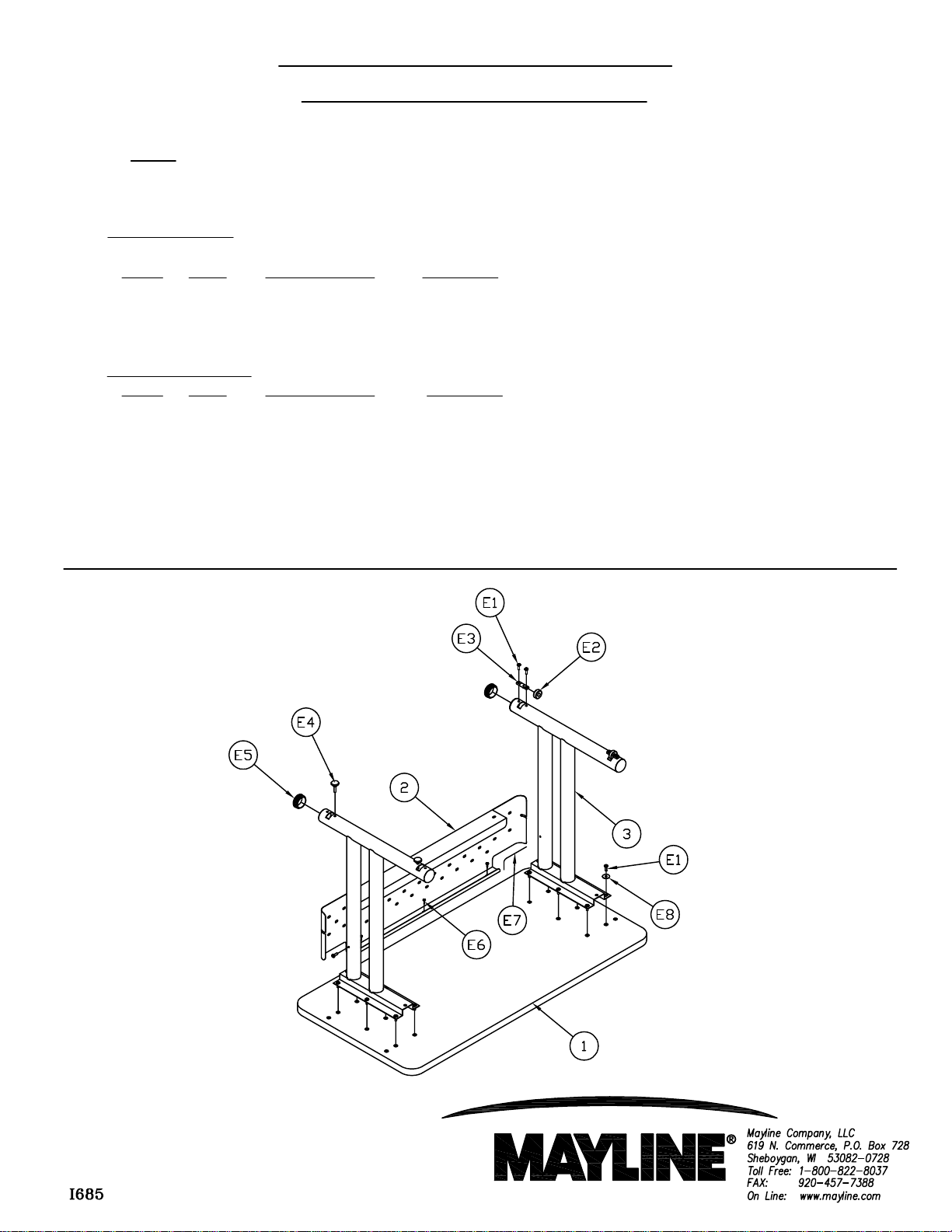
COMPONENTS
REF# QTY. DESCRIPTION PART NO.
1 1 Top CALL ~~**
2 1 Modesty Panel CALL ~~**
3 2 Leg Assembly CALL ~~**
HARDWARE BAG
REF# QTY. DESCRIPTION PART NO.
E1 16 Screw, 1/4-20 700124 *
E2 2 Caster Wheel 700229 *
E3 2 Caster Axle 700230 *
E4 2 Swivel Glide 700169 *
E5 4 End Cap 600109** *
E6 4 Screw, #10 x 3/4" X11 *
E7 2 Grommet Edging F682*
E8 12 Washer, 9/32 x 1 x .06 W83
When ordering components, specific color and/or size information may be required.
Contact a Mayline Customer Service Representative. 1-800-822-8037
(Part No. A7922**)
** Denotes Color Code
~~Denotes Size
* Individual Items, Order by part number.
Page 2
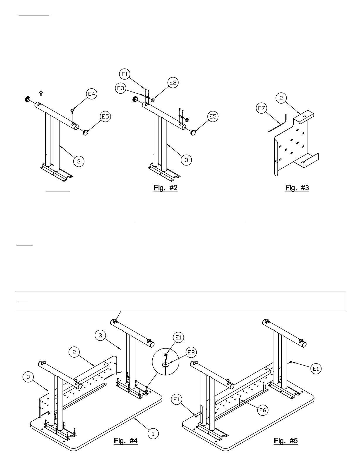
Assembly:
1. Assemble Glides (E4) into inner most threaded holes in Leg (3). Install End Caps (E5) into Leg (3). See Fig.#1
2. Slide the Axle (E3) into the Wheel (E2) and attach Axle (E3) to Leg Assembly (3) using Screws (E1). See Fig.
On multiple tables always assemble the same leg on the same side. When the tables are next to each other
#2
3. Attach the Grommet Edging (E7) to Modesty Panel (2) on each end. See Fig. #3
Fig. #1
4. Place Top (1) face down on a clean flat surface. Attach Leg Assembly (3) onto Top using six Screws (E1) &
six Washers (E8) per Leg. See Fig. #4 DO NOT TIGHTEN AT THIS TIME.
5. Attach Modesty Panel (2) to Leg Assembly using one Screw (E1) per Leg.
Note: Screws are pre-assembled into leg during manufacturing. May need to move screw to other side of Leg.
See Fig. #5.
6. Tighten all Screws (E1).
7. Attach Modesty Panel to Top using Screws (E6). No pilot hole necessary. See Fig. #5
Tip:
you have wheels on one leg and levelers on the other.
(2)
Page 3

Transition Table Assembly Only (Conference vs. Stadium)
Note: Modesty Panel location has two options for assembly.
1. Begin Assembly by determining if the table will be used as Conference or Stadium position. See Fig. #6
2. Follow Instructions on page 2, Steps 1 - 7
Fig. #6
Extra inserts on the underside of the top are for optional ganging kit 10GA & Pie connectors.
(3)
 Loading...