

Page 1
ASSEMBLY INSTRUCTIONS
MAYTRIX LAN FURNITURE
TM
NOTE: Please count and inspect all pieces before disposing
of any carton or packing materials.
When ordering components, specific color and/or size information may be required.
Contact a Mayline Customer Service Representative. 1-800-822-8037
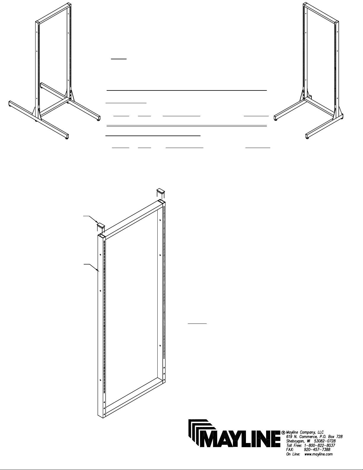
COMPONENTS:
REF.# QTY. DESCRIPTION PART No.
1 1 FRAME ASSEMBLY CALL~~**
** Denotes Color Code
~~Denotes Size
End Cap (E1)
Frame (1)
HARDWARE BAG (PART No. A4359)
REF. # QTY. DESCRIPTION PART No.
E1 2 END CAP F672*
E2 2 1/4-20 HEX NUT T29*
E3 4 WASHER W13*
E4 2 1/4-20 X 2 1/2 SCREW X317*
*for individual item, order that part number
1. Insert End Caps (E1) into upper
ends of Frame (1).
(1)
NOTE: Screws, Washers, and Hex
Nuts will be used later during the
assembly process.
Page 2
LEG ASSEMBLY
NOTE: Please count and inspect all pieces before disposing
of any carton or packing materials.
When ordering components, specific color and/or size information may be required.
Contact a Mayline Customer Service Representative. 1-800-822-8037
COMPONENTS: PRODUCTS 350213L, 350320L
** Denotes Color Code
~~Denotes Size
Frame (1)
REF.# QTY. DESCRIPTION PART No.
2 1 SINGLE L.H. LEG ASSEMBLY CALL~~**
COMPONENTS: PRODUCTS 350213R, 350320R
REF.# QTY. DESCRIPTION PART No.
3 1 SINGLE R.H. LEG ASSEMBLY CALL~~**
HARDWARE BAG (PART No. A4361)
REF. # QTY. DESCRIPTION PART No.
E5 2 END CAP F672*
E6 2 GLIDE Q471*
E7 3 5/16-18 HEX NUT T27*
E8 3 5/16-18 X 2 3/4 SCREW X316*
COMPONENTS: PRODUCT 350214
REF.# QTY. DESCRIPTION PART No.
4 1 DOUBLE LEG ASSEMBLY A4457**
HARDWARE BAG (PART No. A4456)
REF. # QTY. DESCRIPTION PART No.
E5 2 END CAP F672*
E6 3 GLIDE Q471*
E7 3 5/16-18 HEX NUT T27*
E8 3 5/16-18 X 2 3/4 SCREW X316*
*for individual item, order that part number
*for individual item, order that part number
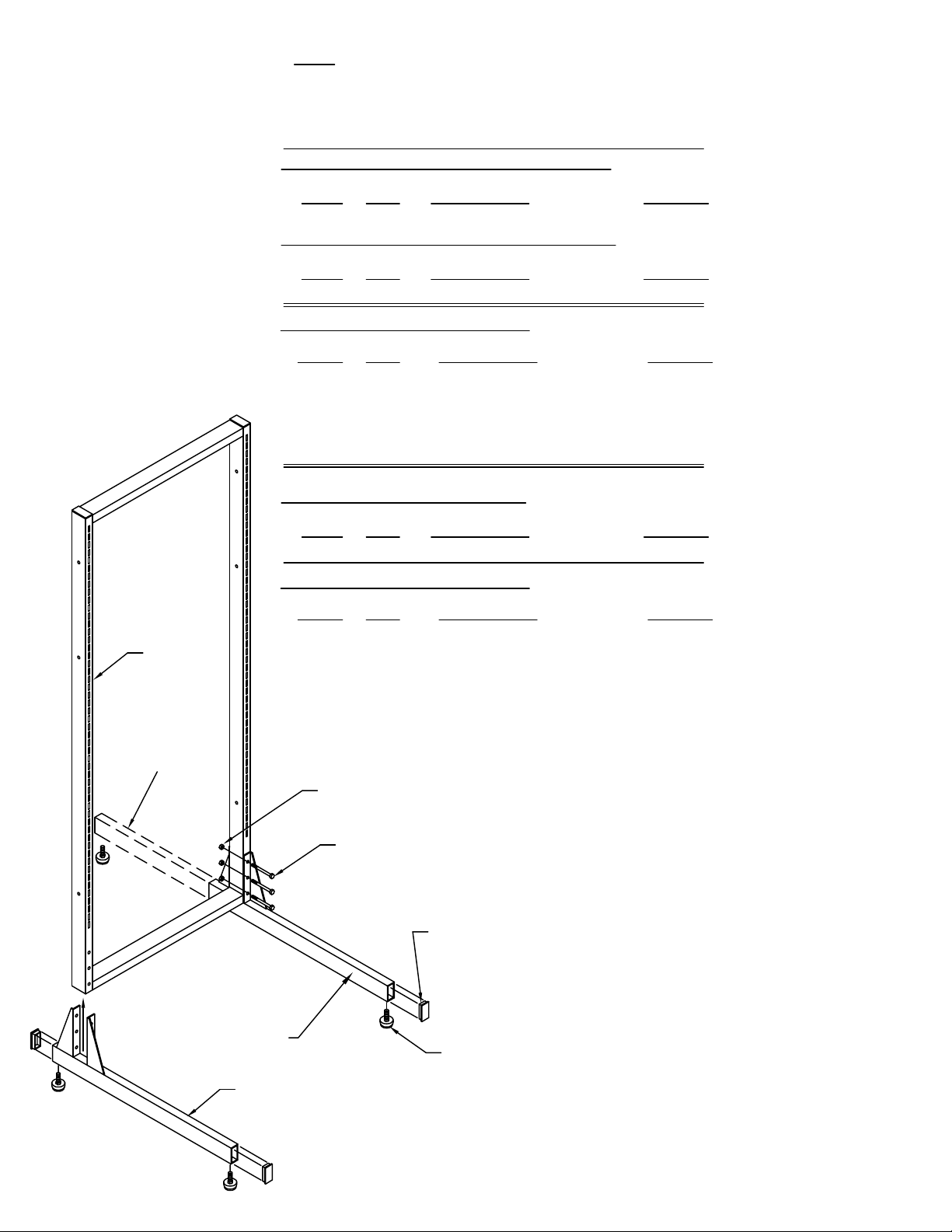
DoubleLeg
Assembly (4)
Right Leg Assembly (3)
Left Leg Assembly (2)
5/16 -18
Hex Nuts (E7)
5/16 -18 x 2 3/4
Screws (E8)
End Cap (E5)
Glide (E6)
(2)
2. Insert End Caps (E5) and
Glides (E6) into ends of Leg
Assemblies (2, 3 or 4).
3. Position Leg Assemblies under
the Frame and attach them with
5/16-18 x 2 3/4 Screws (E8) and
5/16-18 Hex Nuts (E7). Tighten all
nuts securely.
4. Level Frame by adjusting
Glides (E6).
Page 3

CENTER LEG ASSEMBLY
NOTE: Please count and inspect all pieces before disposing
of any carton or packing materials.
When ordering components, specific color and/or size information may be required.
Contact a Mayline Customer Service Representative. 1-800-822-8037
COMPONENTS: PRODUCT 350212
** Denotes Color Code
1/4 -20 x 2 1/2
Screws (E4)
REF.# QTY. DESCRIPTION PART No.
5 1 CENTER LEG SUPPORT A4437**
HARDWARE BAG (PART No. A4360)
REF. # QTY. DESCRIPTION PART No.
E9 1 GLIDE Q471*
E10 4 5/16-18 HEX NUT T27*
E11 4 5/16-18 X 2 3/4 SCREW X316*
*for individual item, order that part number
ASSEMBLY NOTE: Do not tighten bolts until
all components are assembled.
5. Bolt Frames (1) together using 1/4-20 x 2
1/2 Screws (E4), Washers (E3) and 1/4-20 Hex
Nuts (E2) included with frames.
1/4-20
Hex Nuts (E2)
NOTE: Use the uppermost set of holes when
attaching frames of equal height.
Washer (E3)
6. Attach Center Support (5) with 5/16-18 x 2
3/4 Screws (E11) and 5/16-18 Hex Nuts (E10).
Frame (1)
5/16 -18
Hex Nuts (E10)
Frame (1)
Glide (E9)
7. TIGHTEN ALL BOLTS SECURELY.
8. Level Frames by adjusting Glides (E2 and
E13).
NOTE:
It is a MAYLINE recommendation
that NEVER MORE THAN TWO
FRAMES be joined together utilizing
the Center Leg Support (5).
5/16 -18 x 2 3/4
Screws (E11)
Center Support (5)
(3)
Page 4

1/4 -20 x 2 1/2
Screws (E4)
1/4-20
Hex Nuts (E2)
Washer (E3)
Single Frame Assembly
(with Right Hand Leg only)
Double Frame Assembly
Center Support (5)
When connecting an additional
Single Frame Assembly
NOTE:
It is a MAYLINE recommendation
the NEVER MORE THAN TWO
FRAMES be joined together utilizing
the Center Leg Support (5).
8. Assemble the Single Frame per the instructions
on the first page of this instruction sheet.
The single frame Leg Assembly is determined by
the side of the double frame you have chosen to
expand.
9. Bolt the frames together using 1/4-20 x 2 1/2
Screws (E4), Washers (E3), and 1/4-20 Hex Nuts
(E2). Tighten all screws securely.
(4)
10. Level Frame by adjusting the Glides.
 Loading...