

Page 1
ASSEMBLY INSTRUCTIONS
TM
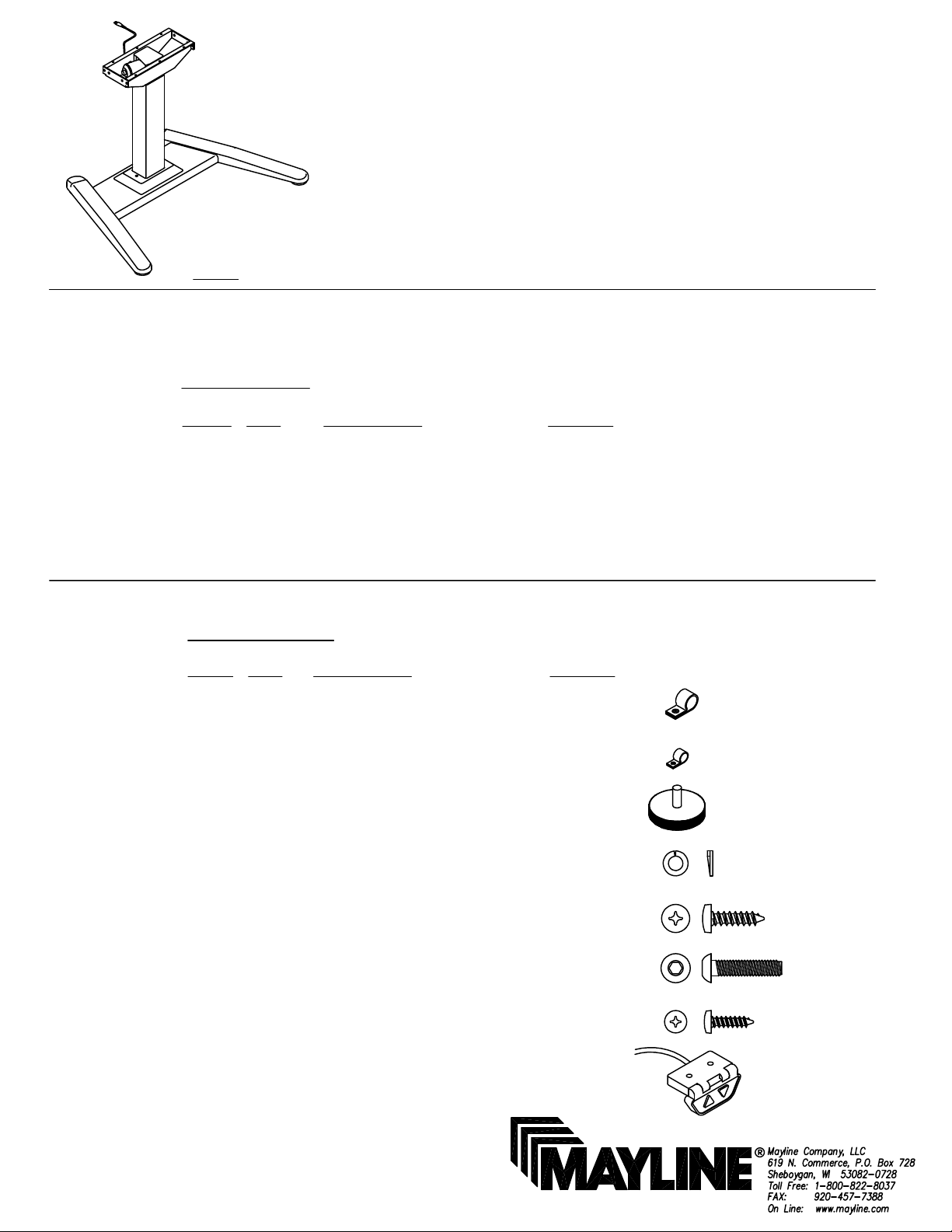
VariTask LT BASE
CATALOG No:
6049
NOTE: Please count and inspect all pieces before disposing of any carton or packing materials.
When ordering components, specific color and/or size
information may be required. Contact a Mayline
Customer Service Representative. 1-800-822-8037
COMPONENTS:
REF. # QTY. DESCRIPTION PART No.
1 1 ACTUATOR ASSEMBLY Z494
2 1 COLUMN BRACE ASSEMBLY A7811
3 1 ANGLED BASE ASSEMBLY A7810
4 1 CONTROL BOX Z461
5 1 MAIN CABLE Z467
6 1 GLIDE CAP (pre-installed) B7895
*for individual item, order that part number
HARDWARE BAG:
REF. # QTY. DESCRIPTION PART No.
E1 1 3/8" CABLE CLAMP F189*
E2 1 1/8" CABLE CLAMP F690*
E3 4 GLIDE Q607*
E4 8 LOCK WASHER W77*
E5 13 #10 X 3/4 PARTICLE BD. SCREW X11*
E6 8 M8 X 16mm CAP SCREW X432*
E7 2 #8 X 3/4 PARTICLE BD. SCREW X5105*
E8 1 DPA SWITCH Z458*
PART No. A7815
Page 2
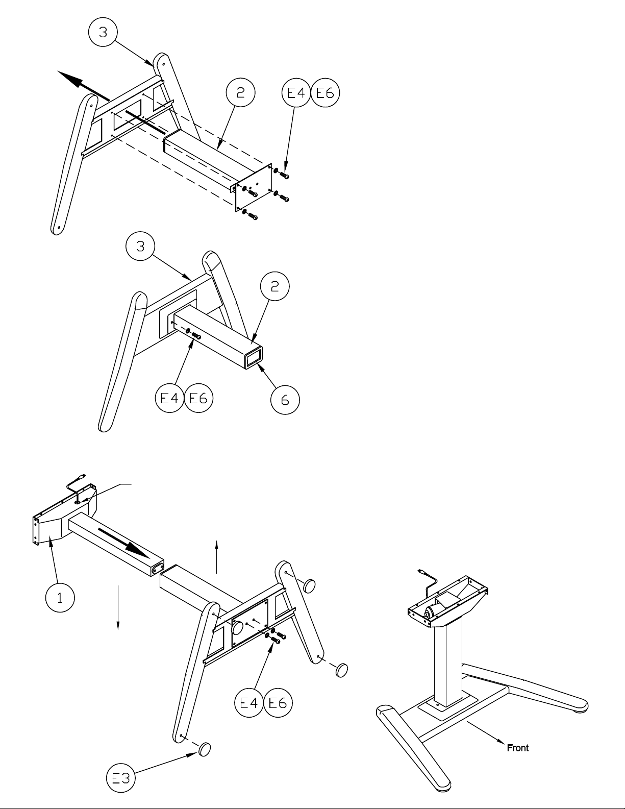
1. Insert Column Brace Assembly (2) through bottom of
Angled Base Assembly (3). Align the holes in the
column assembly plate with the holes in the Base.
2. Install four M8 x 16 mm Cap Screws (E6) and four
Lock Washers (E4). DO NOT TIGHTEN at this time
3. Install two M8 x 16mm Cap Screws (E6) and two
Lock Washers (E4) on either side of Column through
the top of the Base. Tighten all screws, top and bottom,
at this time.
Front
Actuator cord access hole
toward back of unit
Back
4. Slide Actuator Assembly (1) into assembled base.
Position the cord access hole toward the back of the
assembly.
5. Secure Actuator Assembly (1) to the bottom of the
Base (3) using two M8 x 16mm Cap Screws (E6) and
two Lock Washers (E4). Tighten Screws securely.
6. Install Glides (E3) into the Base.
7. Stand assembled unit upright.
Page 3

Electrical Connections:
1
Control Box
Cord
Main
Cable
Actuator
Cord
1. Plug the Main Cable (5) into the Control Box (4).
2. Plug the Actuator Cord (the one exiting the access
hole) into the Control Box (4) using Position #1 .
3. Plug the DPA Switch Cord (E8) into the
"OUTSIDE" Jack Connection on the Control Box (4).
INITIALIZATION of the system:
1. Your table is equipped with soft start / stop drive Actuator system.
To properly function your unit must be initialized at set up.Check
that all cord connections are completely installed into appropriate
conection in Control Box.Plug Main Cable into power supply. Press
down button and hold for 10 to 15 seconds. Note: Column may
move up or down slightly while holding 'DN' button while system
sets correct starting point.
2. Press 'UP' button or 'DN' button to obtain desired
height.
 Loading...