

Page 1
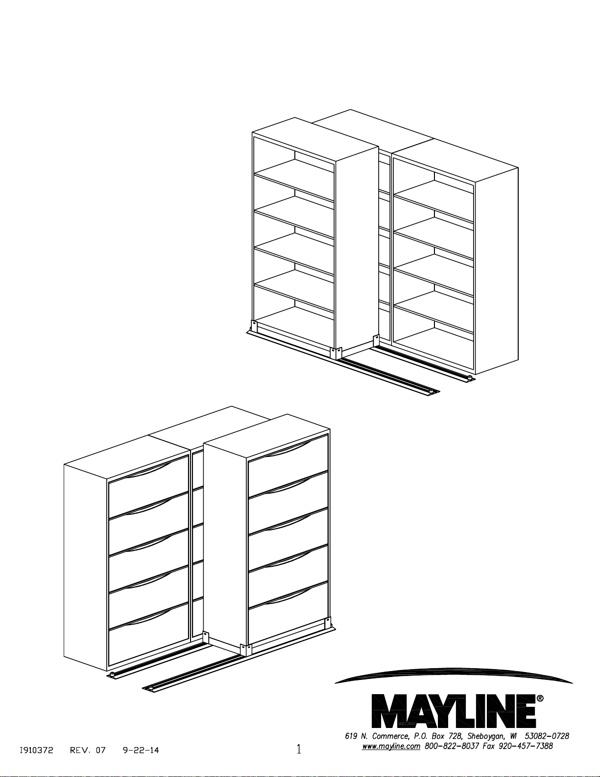
Assembly Procedure
for Kwik Track
Page 2
KWIK TRACK INSTALLATION
MAYLINE recommends the removal of all carpet and padding prior to installing Kwik-Track. We suggest that
carpet be removed the length and width of each track. Product performs best when installed on concrete or tile.
NOTE: MAYLINE cannot assure proper leveling if track is installed on low-pile carpet.
Read all instructions before attempting assembly.
Check floor plan layout. Measure and mark floor for intended layout, preplan exact location
of all units with regard to columns, lights, windows and obstructions.
Check levelness of floor in the proposed install area.
GENERAL NOTES:
1. Installation of Kwik Track begins with the layout of the floor plan. It is imperative for the proper operation
of this system that the tracks be parallel, level and square. On a Kwik Track system the MLTA track, with the
In-track Anti-tip safety feature, is located at the rear.
2. The carriage with the anti-tip guide is designed to be inserted onto the MLTA track after that track is in
the approximate location, but prior to completely securing it to the floor. This will eliminate the need to
disassemble the guide from the carriage.
3. The carriage is shipped completely assembled. If the carriage with the anti-tip guide assembly cannot
be inserted into the MLTA track, it is possible to remove and reinstall the mount assembly. Loosen 1/4" bolts and
remove anti-tip mount(s). Place carriage on track. Care must be taken to properly place the mount(s) tightly to
the channel and angle of the carriage during re-assembly. Re-use fasteners.
4. The KTTV track kits are pre-packaged to include mounting hardware, end stops and shim
material. If KTTV track kits are used in conjunction with each other to obtain longer track runs, insert the
roll pins of one track into the other. This will insure proper track alignment.
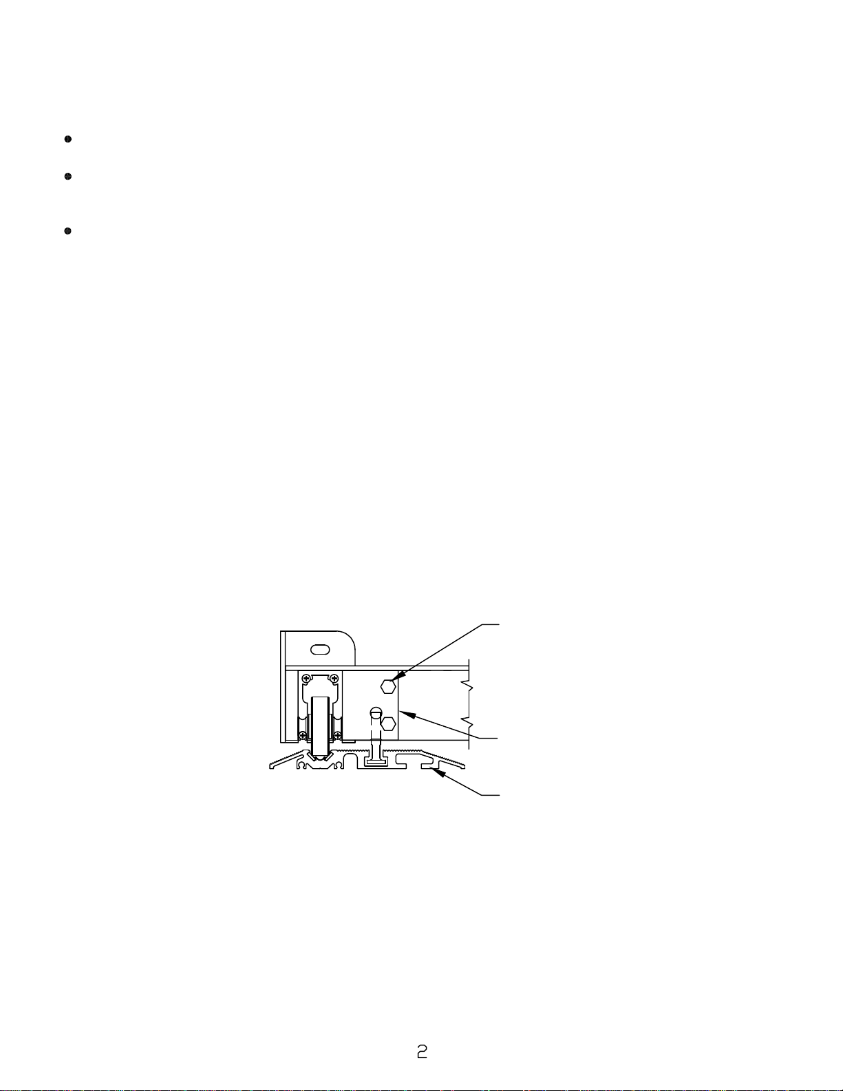
Detail of Anti-Tip Guide
2-BOLT-(1/4-20 X 3/4 GR5)
2 WASHER
ANTI-TIP GUIDE
MLTA TRACK
5. Required tools:
- hammer drill (concrete drill bits are provided in the hardware bag)
- cordless (or electric drill motor) / Phillips screw adapter
- flat and Phillips screwdriver
- 9/16" socket
- hammer
- measuring tape
- chalk line
- level (360 Degree Rotary Laser Level is best suited)
Page 3

The In-track Anti-Tip track (MLTA) will be shipped with the Heavy-duty track (MLT).
End Stop
Tee Nut
Bolt 3/8" x 3"
MLTA Track MLT Track
Install Stationary Shelving per 'Typical Stationary Placement' drawing on Page 4.
Use stationary shelving to assist in aligning track and mobile carriages. The tracks
should extend beyond the stationary shelving at equal dimensions on either side.
Align assembled track parallel to stationary shelving or aisle with approximately
1 1/2" clearance from any obstacle. The MLTA track will be the rear track of the
two track lateral system. Using the holes in the track as a guide, drill 1/4" dia. holes
into the concrete floor deep enough for the track end fasteners. Clean concrete
dust from holes. Level track using shims provided.The track must
be supported along its entire length.
2" Nail-in
Fastener
INSTALL END STOP ON ONE END OF MLTA TRACK.
BE SURE TEE NUT FOR OPPOSITE
BUMPER IS UNDER TRACK PRIOR
TO FINAL TRACK ANCHORING.
Hilti KBTZ
Bolt 3/8" x 3"
2" Nail-in
Fastener
Hammer the fastener(s) into the floor
through holes in both ends of track.
2" Nail-in
Fastener
Confirm joints are still properly
seated, track is straight and level.
End Stop
Tee Nut
Screw
Roll Pins
Anchor
Pin Hole
Anchor
Pin Hole
Maintaining careful alignment of the MLTA, drill a 3/8" hole into the floor and install the mid-track
3/8" x 3" HILTI KBTZ Concrete bolts at every available anchor point in the track. The strength of the
anti-tip is in the anchors. Make sure they are tightened properly.
CAUTION: Hole depth for 3/8" HILTI bolt must be a consistent depth as to prevent tripping hazard.
Screw
Hilti KBTZ
Once the anti-tip track is secured, the remaining tracks can be set in the approximate location.
Place one carriage on the track to determine spacing. Verify carriage wheels are centered in the
channels and in the track.
The tracks must be square, parallel, and level to each other to insure proper operation. Measure each
set of tracks and the entire system, corner to corner, to verify that each distance is the same. Once each
cross measurement is the same, the system is square and parallel.
When the tracks are square, parallel, level and shimmed as required drill the end holes. Install remaining
anchors. It is the installer's responsibility to verify smooth operation of the system.
Place the remaining carriages on the track, verify smooth operation and install the remaining end stops on
MLT and MLTA tracks.
Page 4

Install the shelving per the manufacturer's specifications. Secure to the mobile carriage with TEK screws
through corners/center plates. TEK screws are found in the accessory box.
Install Lateral File, FileHarbor , and Flip-n-File cabinets to the Mobile Carriage with TEK screws through
TM
corners/center plates, TEK screws found in accessory box.
NOTE: MAYLINE LATERAL FILE CABINETS REQUIRE THE REMOVAL OF LEVELERS FOR ALL
UNITS THAT ARE PLACED ONTO A KWIK TRACK CARRIAGE.
TYPICAL STATIONARY PLACEMENT
SINGLE ROW OF
LATERAL MOVING UNITS
TYPICAL STATIONARY PLACEMENT
TWO ROWS OF
LATERAL MOVING UNITS
 Loading...