

Page 1

ASSEMBLY INSTRUCTIONS
POWER BASE
NOTE: 1.) Install base so Power Plug
is easily accessible.
2.) Weight distribution on various size tops, as it effects
stability, is the responsibility of the installer.
HARDWARE BAG (PART No. A4176) - 120v Power Base
*for individual item, order that part number
REF. # QTY. DESCRIPTION PART No.
E1 4 1/4-28 X 1/2 SCREW X218*
E2 1 HEX WRENCH X178*
E3 4 #10 X 5/8 SCREW X5108*
E4 2 CABLE CLAMP F191*
E5 4 1/4-28 KEPS NUT T25*
E6 - --------- ---
HARDWARE BAG (PART No. A3372) - 220v Power Base
*for individual item, order that part number
REF. # QTY. DESCRIPTION PART No.
E1 4 1/4-28 X 1/2 SCREW X218*
E2 1 HEX WRENCH X178*
E3 4 #10 X 5/8 SCREW X5108*
E4 2 CABLE CLAMP F191*
E5 - ------------- ----- E6 1 POWER CORD SET Z242*
(1)
Page 2
Screw (E1)
KEPS Nut (E5)
Fig. 1
Fig. 2
Note:
Board Brackets may
vary in appearance
per top.
Screw (E1)
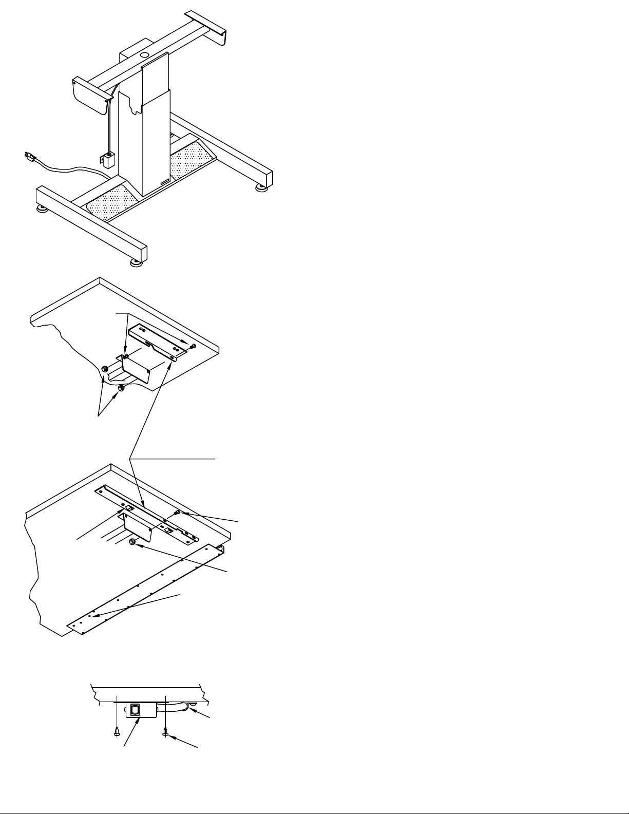
ASSEMBLY INSTRUCTIONS
POWER BASE with NO TILT
1. Assemble Top and Brackets per instructions
included with the Top.
NOTE: If you are not receiving a MAYLINE top,
locate brackets as shown in Fig. 3.
2. With the assistance of another person,
position the Top Assembly and hook the board
bracket hooks onto the tilt pad edge. Secure in
place with two 1/4-28 x 1/2 screws (E1) and two
KEPS Nuts (E5). Tighten with Wrench (E2).
3. Mount switch to underside of Pencil Trough or
Work Surface with two #10 x 5/8 Screws (E3).
Use Cable Clamp (E4) and #10 x 5/8 Screws
(E3) to secure switch cable. See Fig. 3 & 4
4. Attach Power Cord (E6) - 220v unit only.
5. Adjust Glides as required to level.
NOTE:
Use this hook to
attach Top to Tilt
Pad Edge
Switch Box
KEPS Nut (E5)
Holes for attaching
Switch Box on Tops
with Pencil Trough
Fig. 3
Cable Clamp (E4)
Screw (E3)
Fig. 4
(2)
Page 3

Power
Cord (E6)
Tilt Pad
Fig. 1
ASSEMBLY INSTRUCTIONS
POWER BASE with POWER TILT
NOTES:
Some units are supplied with two R.H. Board
Brackets in applications where a shorter bracket is
required for mounting clearance. Quantity of
Machines Screws (E1) varies by model.
1. Assemble Top and Brackets per instructions
included with the Top.
NOTE: If you are not receiving a MAYLINE top,
locate brackets as shown in Fig. 2.
NOTE:
Use this hook to
attach Top to Tilt
Pad Edge
Note:
Board Brackets may
vary in appearance
per top.
Holes for attaching
Switch Box on Tops
with Pencil Trough
Fig. 2
Screw (E1)
2. Position Tilt Pads to near vertical position
before installing Top.
3. With the assistance of another person, position
the Top Assembly and hook the board bracket
hooks onto the tilt pad edge. Secure in place with
two 1/4-28 x 1/2 screws (E1) and tighten with
Wrench (E2).
4. Mount switch to underside of Pencil Trough or
Work Surface with two #10 x 5/8 Screws (E3).
Use Cable Clamp (E4) and #10 x 5/8 Screws (E3)
to secure switch cable. See Fig. 2 & 3
5. Attach Power Cord (E6) - 220v unit only.
6. Adjust Glides as required to level.
Switch Box
Cable Clamp (E4)
Screw (E3)
Fig. 3
(3)
 Loading...