

Page 1
Kwik-File, LLC
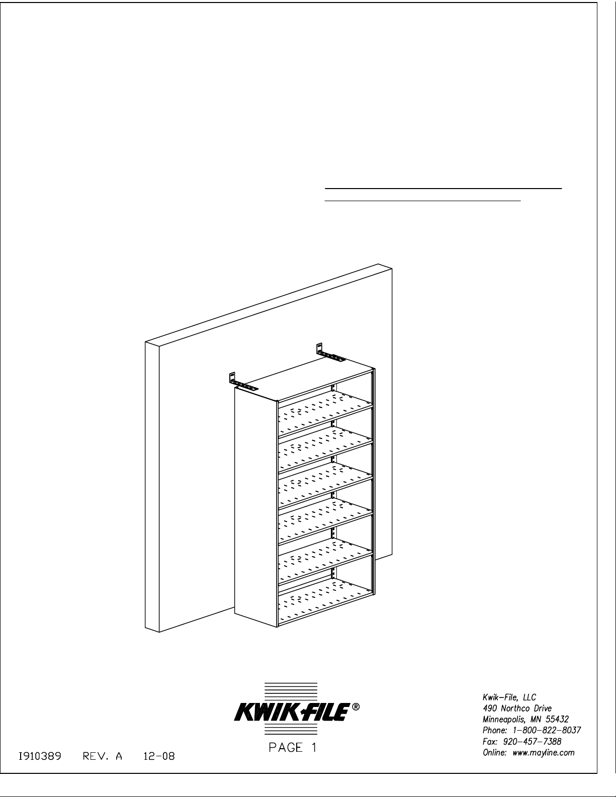
WALL ANTI TIP, 4-POST
Tools Required
- Drill
- 1/4" Drill Bit
- Phillips Screw Driver
- 7/16" Socket
:
Hardware List (913045R)
- 1/4-20 x 1-1/4" Phillilps Pan Head Scrwe (2)
- 1/4-20 Nut with Star Washer (2)
NOTE: INSTALLER TO PROVIDE HARDWARE TO
SECURE 'WALL ANTI TIP' TO THE WALL
:
Page 2
Installation Notes:
1. 4-Post unit must be no further than 8-1/2" from the wall
2. Installer is responsible for hardware to secure the Wall Anti Tip brackets to the wall.
3. Wall Anti Tips brackets must be secured to a stud in the wall
4. The Wall Anti Tip brackets must be secured to the 4-post unit through the top shelf support
and the top shelf. Failure to do so will result in an failed installation.
Installation Procedure:
1. Identify the final position for the 4-Post unit. The 4-Post unit can be no greater than 8-1/2"
from the wall. Once the position of the 4-Post unit has been determined, locate a minimum of
two studs in the wall. Place a cooresponding mark on the 4-post unit for proper alignment of
the brackets.
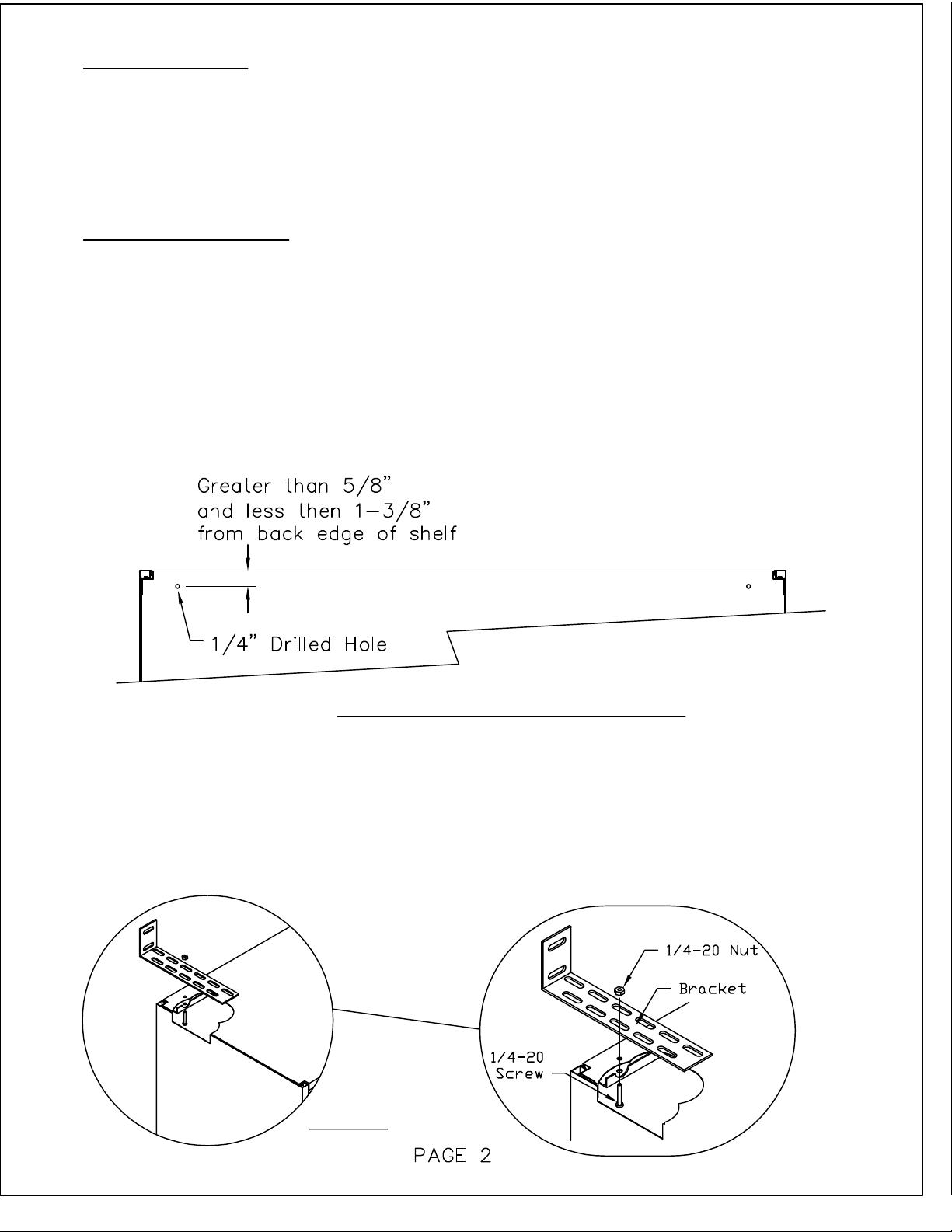
2. Mark the proper location to drill a 1/4" hole through the top shelf and the shelf support. The
hole location must be greater then 5/8" and less than 1-3/8" from the back edge of the shelf.
This will ensure that the 1/4" hole will pass through the 4-Post shelf support. (Fig. 2.1)
(Fig. 2.1) Birds Eye View of 4-Post Unit
3. Drill a 1/4" diameter hole at the locations that were just marked on the 4-Post unit. Use a
clamp to secure the shelf and shelf support together during drilling.
4. Secure Wall Anti Tip to 4-Post unit using the provided hardware. (Fig. 4.1) Tighten
hardware by using a 7/16" socket and a phillips screw driver.
(Fig. 4.1)
Page 3

5. Secure brackets to the wall. Installer to provide the appropriate hardware to securing to the
wall.
 Loading...