

Page 1
Kwik-File
Kwik-File
4-POST SHELVING
(See Pages 1 thru 4)
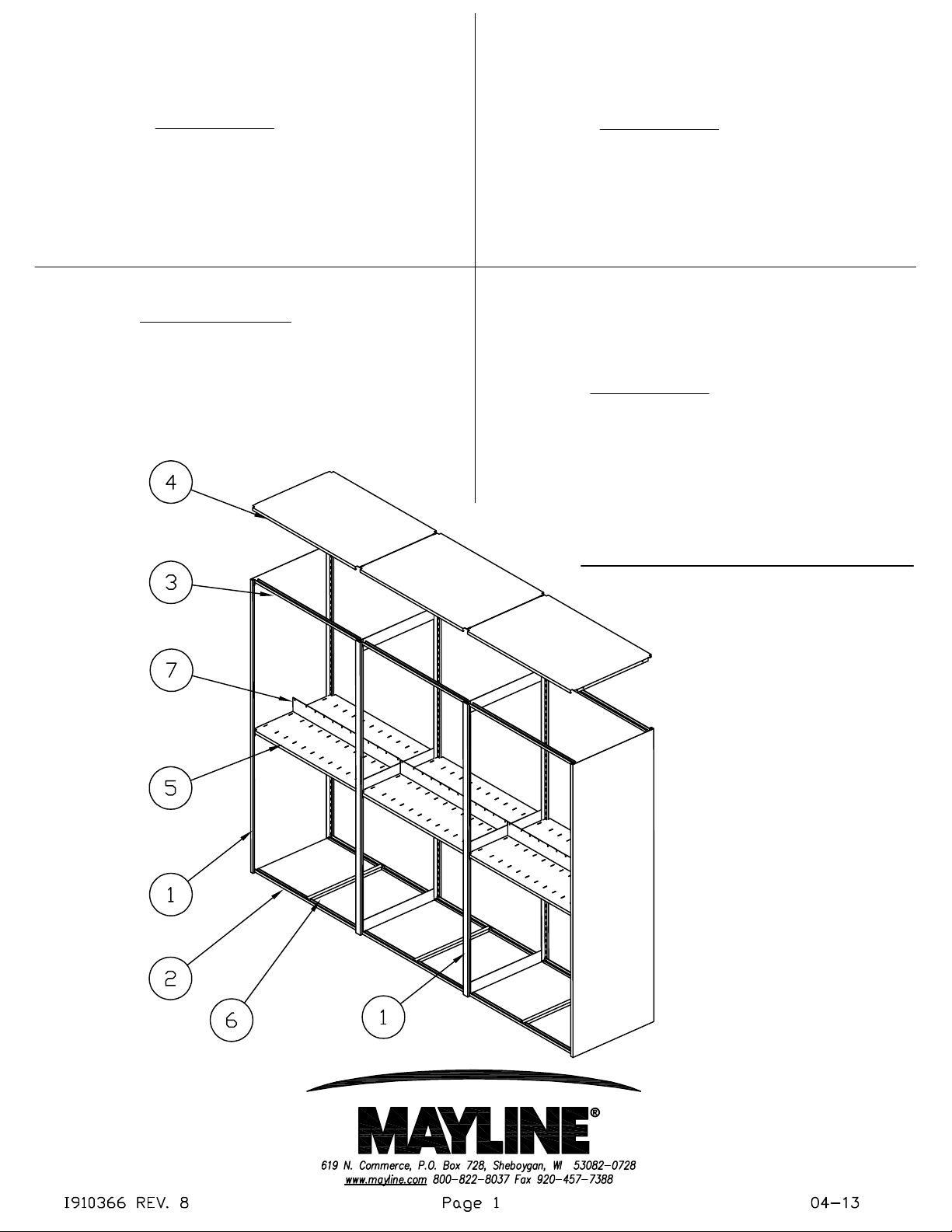
COMPONENTS:
1. Uprights
2. Bottom Shelf Support
3. Standard Shelf Support
4. Unslotted Shelf Canopy
5. Slotted Shelf
6. Shelf Reinforcement
7. Common Stop
TOOLS REQUIRED:
1. Rubber Mallet
X-RAY SHELVING
(See Pages 1, 5 & 6)
COMPONENTS:
1. Uprights
2. Bottom Shelf Support
3. X-ray Shelf Support
4. Unslotted Shelf Canopy
5. Slotted Shelf
6. X-ray Std./Btm. Shelf Reinforcement
7. Common Stop
Kwik-File
4-POST ACCESSORIES
(See Pages 7 thru 16)
COMPONENTS:
1. Upper and lower spreaders
2. Shelf reinforcements
3. Slide attachment bracket kits
4. Drawers
5. Drawer lock
6. Partition supports and partitions
7. Support bar
8. 18" Shelves
9. 36" Shelves
Page 2
The components of the basic 4-Post System are:
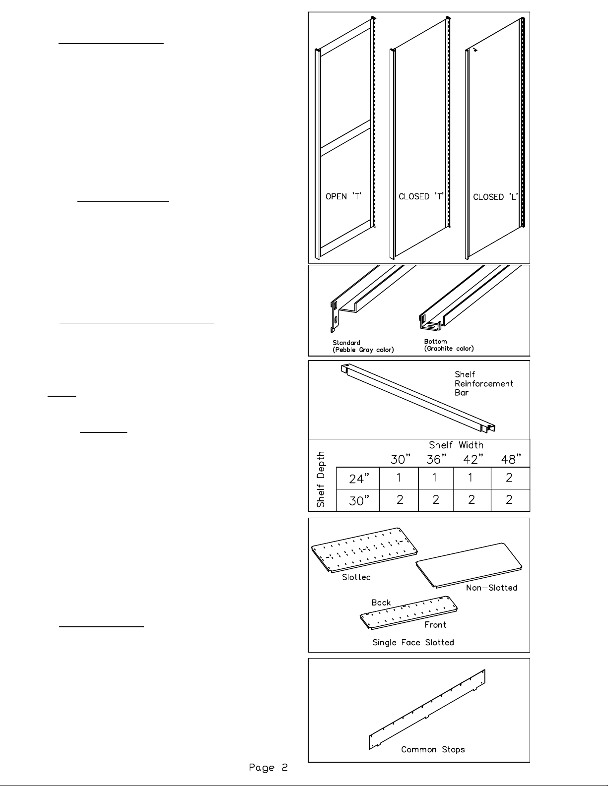
1. VERTICAL UPRIGHTS: Three styles are used:
A.) Open 'T'
B.) Closed 'T'
C.) Closed 'L'
Closed 'L' uprights are located at either end of a
4-Post range. Open and Closed 'T' are located
internally in a 4-Post range. Each style contains
tapered slots vertically along the uprights to accept
the shelf supports that are positioned horizontally.
The narrow portion of the tapered slots must face
downward. Tapered slots are at 1-1/2"
center-to-center vertical spacing.
2 & 3. SHELF SUPPORTS: Two styles are used:
A.) Standard shelf supports (Pebble Gray)
B.) Bottom shelf supports (Graphite)
The supports are inserted into the slots of the vertical
upright to form the horizontal support for the shelf.
Standard shelf supports are Pebble Gray in color.
The bottom shelf supports are Graphite in color and
are used only at the bottom of the unit. Supports
should be secured into place with a rubber mallet.
4. SHELF REINFORCEMENT BARS:
Reinforcements are used on "Double Face Shelves
(24" and 30" shelving only). These bars are
positioned across the shelf supports to add strength
to the shelf. Shelf reinforcement quantities are
illustrated in the matrix.
NOTE: Adjust the reinforcement position if it
interferes with shelf slots.
5 & 6. SHELVES: three styles are used:
A.) Single Face Slotted.
Depth is either 12" or 15". Two rows of slots exist for
divider installation. Three slots are also located in
the back of the shelf for the center/back stop
installation.
B.) Double Face Slotted.
Depth is either 23" or 30". Four rows of slots exist
for the divider installation. Three slots are also
located in the middle of the shelf for the center/back
stop installation.
C.) Single & Double Face Non-slotted.
Shelves are positioned on the shelf supports and
also used as the canopy top. which is typically a
non-slotted shelf.
7. COMMON STOPS:
Placed in the back of single face and middle of
double face shelves. Held in place by dividers.
Page 3
Kwik-File
4-POST Reference Shelf
Assembly Instructions
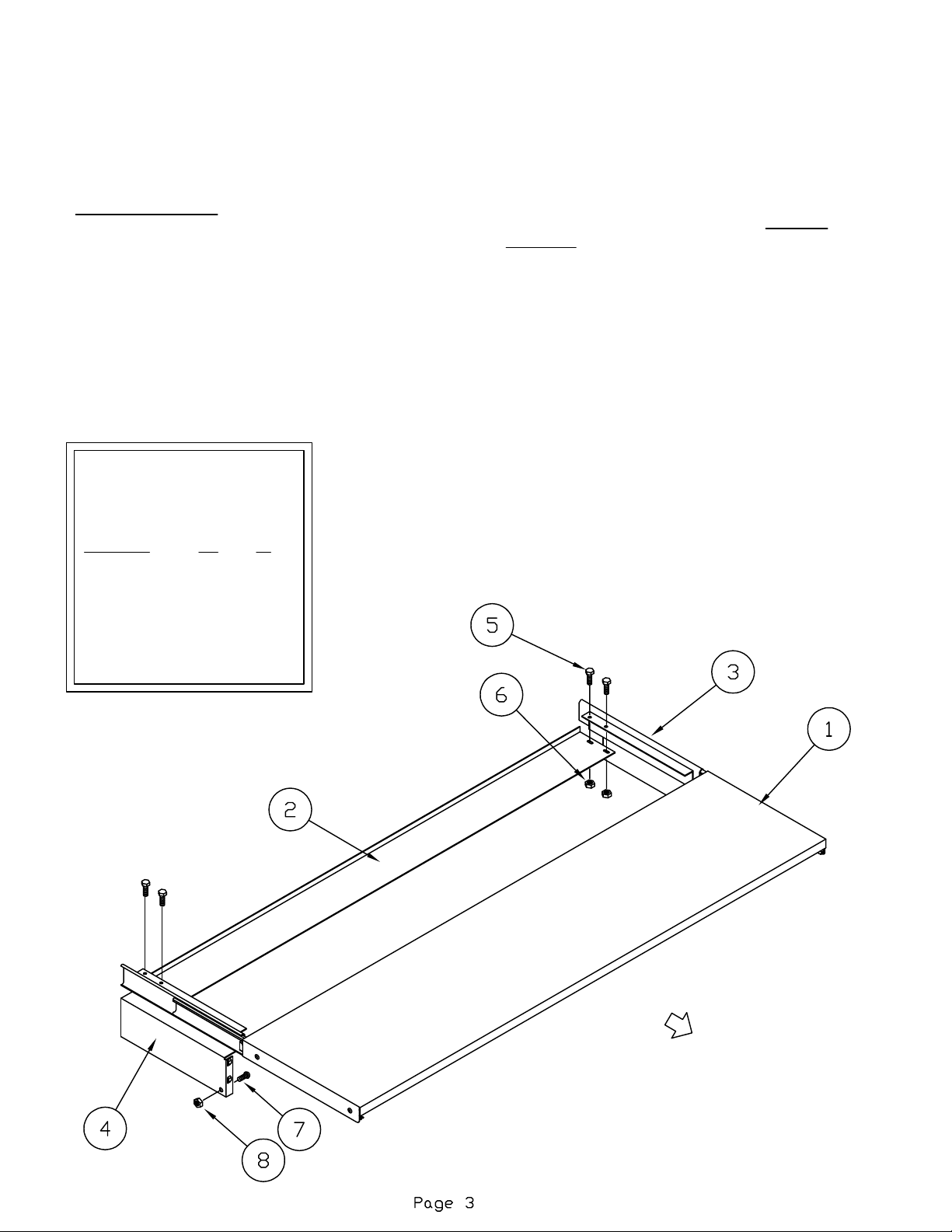
COMPONENTS:
1. Reference Shelf Assembly (1)
2. Stabilizer Bracket (1)
3. R.H. End Bracket Slide Assembly (1)
4. L.H. End Bracket Slide Assembly (1)
5. 10-32 x 3/8 Pan Head Screw (4)
6. 10-32 KEPS Nut (4)
7. 1/4-20 x 1/2 Hex Head Screw (2)
8. 1/4-20 KEPS Nut (2)
Pullout Reference Shelf
Model numbers:
Model: W H
EF24RS 24" 12"
EF30RS 30" 12"
EF36RS 36" 12"
EF42RS 42" 12"
EF48RS 48" 12"
Secure stabilizer bracket to reference shelf end with
#10-32 x 1/2 screws and KEPS nut. DO NOT
TIGHTEN hardware until reference shelf is installed.
Slide the reference shelf on the end bracket slide
assemblies, notches are provided on the back side of
the shelf. Slide the shelf back until the front of the
slide is resting with the flat fold of the shelf.
Now tighten the stabilizer bracket hardware. Be sure
that the slide brackets are parallel.
F
R
O
N
T
Page 4
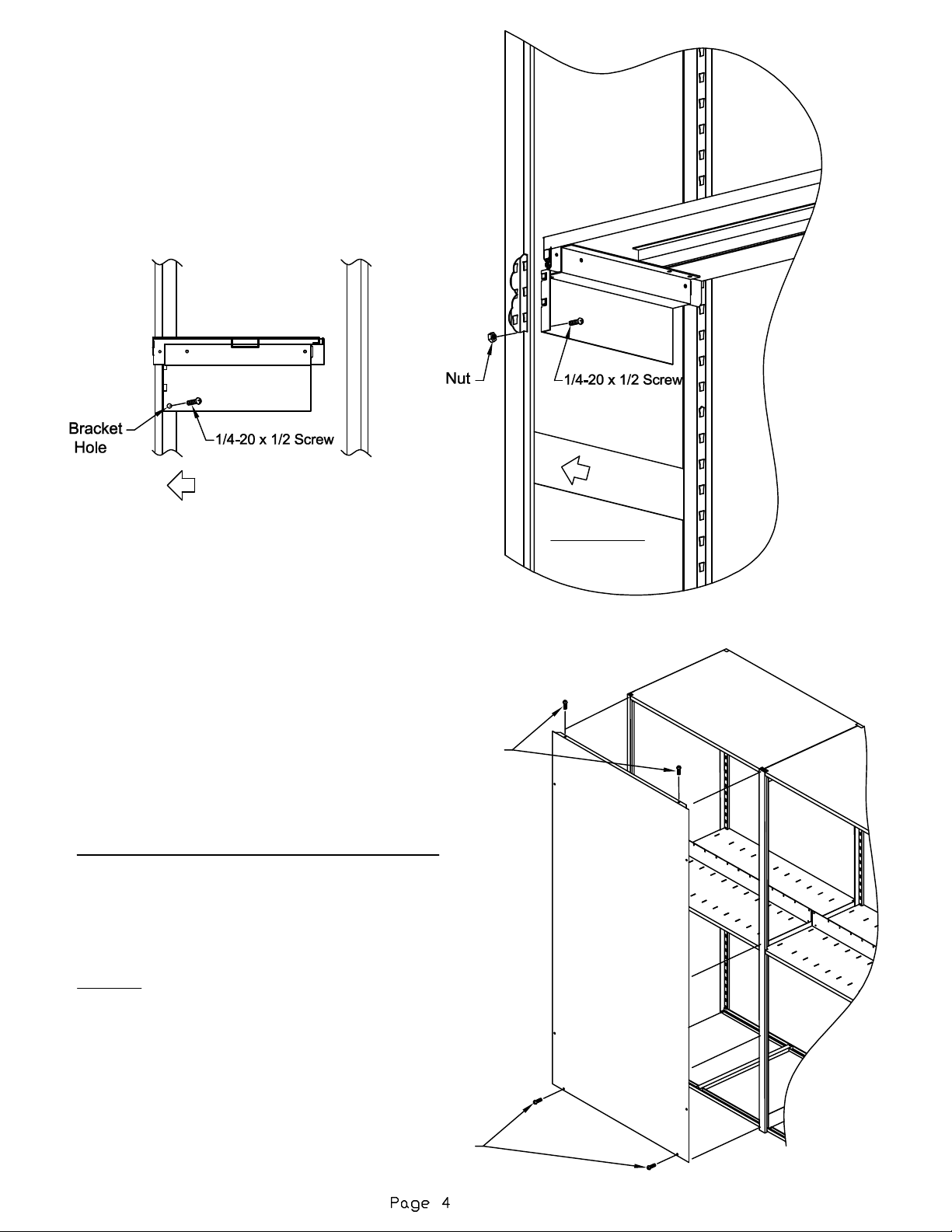
When a Pull-Out Reference Shelf is used,
Set each reference shelf end bracket assembly into
slots in upright.
Using the holes in the bracket as pilot holes, drill 2
holes (1/4" diameter) into the upright. Secure the
bracket to the upright with 1/4-20 x 1/2 screw and
nut. Do both brackets.
FRONT
F
R
O
N
T
These screws
are optional
BACK PANEL or CENTER PANEL INSTALLATION
Rest the panel flange on top of the 4-Post assembly
and center the panel side to side. Peal away
protective film from tape on inside of panel and press
firmly into position.
Optional: Attach the panel using (4) #10 TEK
self-drilling screws. Located at the top flange into top
shelf and along the bottom into the bottom shelf. A
power driver must be used to thread the screws into
the uprights.
UNDERSIDE of
Sliding Shelf shown
These screws
are optional
Page 5
X-Ray Product
Specifications:
86" tall uprights provide for (3) 15.125" openings
and (2) 16.625" openings.
Shelving to hold 8 pounds per linear filing inch.
48"x18" shelf = 384 pounds per shelf
48"x36" shelf = 768 pounds per shelf
The components of the basic X-Ray Shelving
System are:
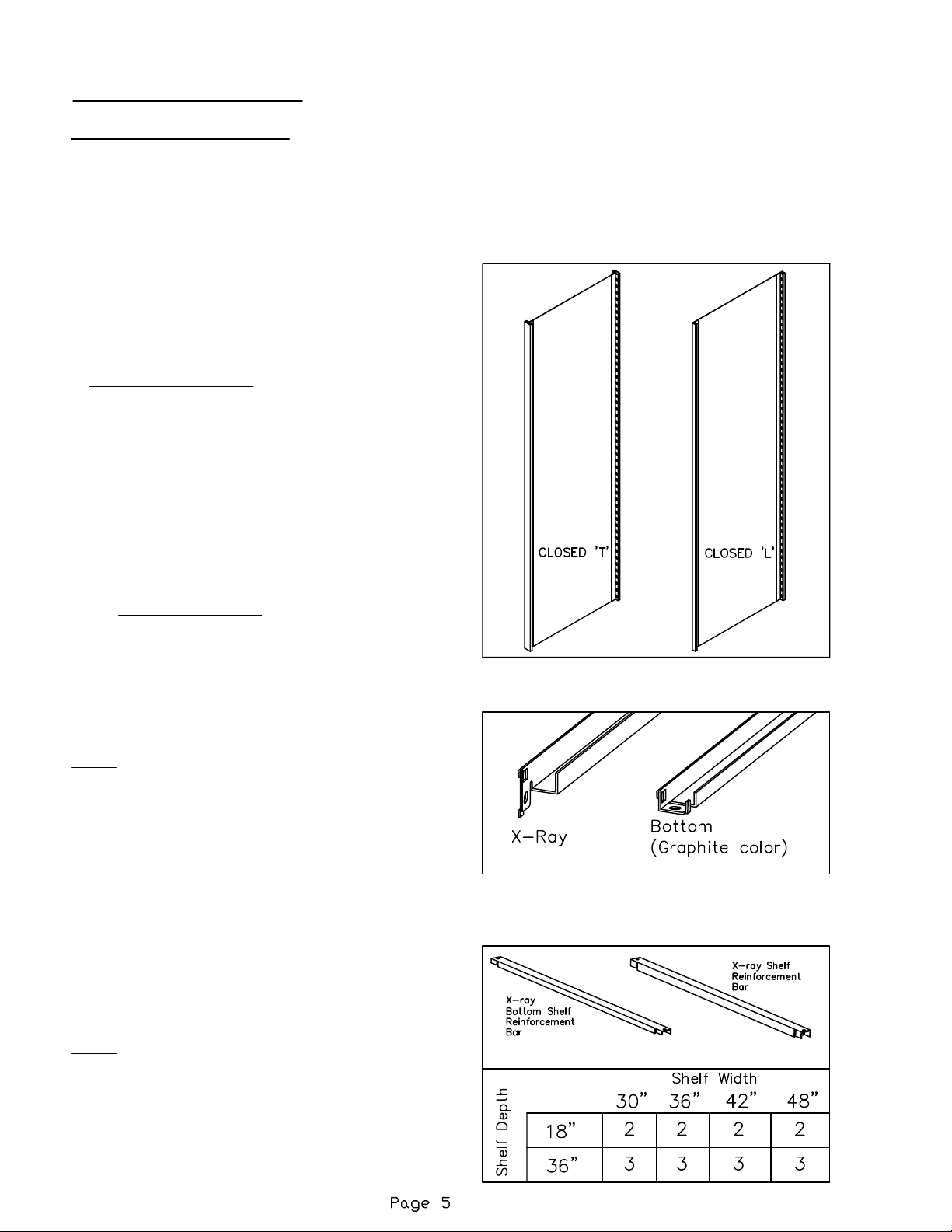
1. VERTICAL UPRIGHTS: Two styles are used:
A.) Closed 'T'
B.) Closed 'L'
Closed 'L' uprights are located at either end of a
4-post range. Closed 'T' are located internally in a
X-ray range. Each style contains tapered slots
vertically along the uprights to accept the shelf
supports that are positioned horizontally. The
narrow portion of the tapered slots must face
downward. Tapered slots are at 1-1/2"
center-to-center vertical spacing.
2 & 3. SHELF SUPPORTS: Two styles are used:
A.) X-ray shelf supports
B.) Bottom shelf supports
The supports are inserted into the slots of the
vertical upright to form the horizontal support for
the shelf. The bottom shelf supports are used only
at the bottom of the unit. Supports should be
secured into place with a rubber mallet.
NOTE: X-ray shelf supports are 1/2" deeper than
the bottom X-ray shelf supports.
4. SHELF REINFORCEMENT BARS: Two styles
are used:
A.) X-ray shelf reinforcement (deep channel)
B.) Bottom shelf reinforcement (shallow channel)
Reinforcements are used on all X-ray shelves with
the exception of the canopy top. These bars are
positioned across the shelf supports to add
strength to the shelf. Shelf reinforcement
quantities are illustrated in the matrix.
Adjust the reinforcement position if it interferes
with shelf slots.
NOTE: X-ray shelf reinforcements are 1/2" deeper
than the X-ray bottom shelf reinforcements.
Page 6

5 & 6. SHELVES: Two styles are used:
A.) Single Face Slotted
Depth is 18". Two rows of slots exist for
divider installation. Three slots are also
located in the back of the shelf for the
center/back stop installation.
B.) Double Face Slotted
Depth is 36". Four rows of slots exist for the
divider installation. Three slots are also
located in the middle of the shelf for the
center/back stop installation.
C.) Single & Double Face Non-slotted
Shelves are positioned on the shelf supports
and also used as the canopy top, which is
typically a non-slotted shelf.
7. COMMON STOPS:
Placed in the back of single face and middle
of double face shelves. Held in place by
dividers.
Back / Center Panel
Assembly Instructions
(Optional Item)
Back Panel (indicated by offsets running
the long length of the panel) & Center
Panel (no offsets) installation
Rest the panel flange on the top of the
4-Post assembly and center the panel
side to side. Peal away protective film
from tape on inside of panel and firmly
press into position.
Optional: Attach the panel using (4) #10
TEK self-drilling screws located at the
top flange into top shelf and along the
bottom into the bottom shelf (hardware
bag of 30 screws is provided). A power
driver must be used to thread the
screws into the uprights. Verify with end
user if they would like the screws
installed into the panel.
Page 7

Rollout Drawer Assembly / Installation
UPPER AND LOWER SPREADERS: When
specifying roll out drawers you will use two
lower spreaders and two upper spreaders for
each 4-Post unit. The lower spreader will
replace the lower shelf support, its additional
height will help to stabilize the unit. The upper
spreader would replace a shelf support in the
area above the top drawer, again the additional
height will help to stabilize the unit. Both upper
and lower spreaders are installed the same as
our standard shelf support. Place the tabs in
the holes in uprights and use a rubber mallet to
seat in place.
When attaching shelving to the floor
use (4) 1/4" masonry wedge anchors
for concrete or (4) 1/4" wood screws
when going into another material.
Not recommended for mounting on a
carpeted floor.
Page 8

SHELF REINFORCEMENTS: A special shelf
reinforcement is used above the upper spreader, all
other shelves will use the X-ray bottom shelf
reinforcements (X18SRB, X36SRB)
Shelf
Reinforcement
Bar
Page 9

18"/36" LH
18" Bracket / Slide Installation
SLIDE ATTACHMENT BRACKET KITS:
These kits include four brackets for both the 18" and
36" 4-Post. The 18" bracket kit will include two slides.
The 36" bracket kit will include four slides.
The brackets are attached much like the shelf
supports. The two pieces are slid together and the tabs
get located into the slots in the vertical uprights and are
seated in place with a rubber mallet. After they are
seated four screws get added to each bracket, two for
bracket stops and the other two to complete bracket
assembly.
A hardware kit (707900) with eight screws and six
brackets stops is included to complete each bracket kit.
1/4-20 X
BRACKET
STOP (6)
1
" SCREW (8)
2
BRACKET ASM.
18"/36" RH
1/4-20 X
1
" SCREW (8)
2
NOTE:
L.H. Brackets have
SQUARE holes.
R.H. Brackets have
ROUND holes
1/4-20 X
1
" SCREW (8)
2
BRACKET ASM.
18" RH
(ROUND HOLES)
BRACKET ASM.
18" RH
(ROUND HOLES)
BRACKET
STOP (6)
BRACKET ASM. 18" LH
(SQUARE HOLES)
F
R
O
BRACKET ASM.
BRACKET ASM.
18"/36" RH
N
T
Page 10

36" Bracket / Slide Installation
I
NSTALLATION OF BRACKETS FOR ROLLOUT DRAWERS.
For proper spacing and installation of drawers, brackets should be installed
from the bottom up. The location of the bottom drawer and remaining brackets
will be different depending on the height of the drawer being installed. Each
bracket has two tabs on each end of each bracket assembly that get installed
into corresponding open slots on the four post upright.
BOTTOM DRAWER BRACKET INSTALLATION:
10.5" drawer (use 3rd & 4th slots above lower spreader)
6" drawer (use 2nd & 3rd slots above lower spreader)
4.5" drawer (use 1st & 2nd slots above lower spreader)
REMAINING DRAWER BRACKET INSTALLATION:
10.5" drawer (use 3rd & 4th slots above drawer front)
6" drawer (use 2nd & 3rd slots above drawer front)
4.5" drawer (use 1st & 2nd slots above drawer front)
NOTE:
L.H. Brackets have
SQUARE holes.
R.H. Brackets have
ROUND holes
1/4-20 X
1
" SCREW (8)
2
BRACKET ASM.
18" / 36" RH
1/4-20 X
BRACKET
STOP (6)
1
" SCREW (8)
2
BRACKET ASM.
BRACKET
STOP (6)
36" RH
F
R
O
N
T
Page 11

DRAWERS: Drawers are available in
three heights: 4.5", 6", and 10.5" and in
four widths, 30", 36", 42" and 48" and
depths of all are 15.738".
The drawers are available only for the
18" and 36" deep 4-Post units.
4-Post drawers can be configured
using any of the different drawer heights
in each of the different cabinet widths.
To install drawers place tabs in
drawers into slots on the slides. (see
picture)
4-Post Upright
Slide
F
R
O
N
T
Page 12

DRAWER LOCK: There is a cam lock for the 6" and
10.5"drawers. To install you must carefully remove
the knockout on the lower right hand side of drawer
face. Using a hammer and a screw driver, tap on
the areas not retained going back and forth till
knockout drops out.
Remove nut from lock, add rotation stop washer,
cam and screw to the lock and feed through hole in
drawer, replace the nut and tighten. Lock cam
should be in the down position and turn 90 degrees
to the lock position. The lock should catch on the
inside of the upright but may require a slight
adjustment.
Replacement Parts:
FPALOCKREPL - Lock Assembly FPA
NOTE:
4-Post drawers are
keyed alike from factory
Lock assembly shown
Locked and Unlocked
LOCKED
UN-LOCKED
Page 13

PARTITION SUPPORTS: If partitions
are going to be used, a partition
support will be required at the front of
each drawer. This option is available
only on the 4.5" and 6" drawers, it is not
an option on the 10.5" drawer.
Partition Support
PARTITIONS: There are two
different heights used, the 4.5" and
the 6". They are used along with
the partition supports for the
separation of media. They will
hook into slots in the partition
support at the front and into the
slots in the drawer bottom.
Page 14

SUPPORT BAR: A support bar is required at the
front of the 10.5" drawer when hanging files are
going to be used. It hooks into the slots at the top
front of the drawer.
FELT PADS: The hardware kit includes 4 felt
pads which may be added to the back of the
drawer fronts. The pads should be placed near
the edge of the drawer approximately 1" up from
the bottom or 1" above the lock if lock is used and
1" down from the top (as shown).
Support Bar
Pad Loation
when Lock is used
Page 15

18" SHELVES: The four post units with drawers
will use a shelf that has slots for the back stop and
dividers arranged for both letter and legal media.
The top shelf will not be slotted.
Slotted
Shelf
Page 16

36" SHELVES: The four post units with drawers
will use a shelf that has slots for the back stop and
dividers arranged for both letter and legal media.
The top shelf will not be slotted.
Slotted
Shelf
 Loading...