

Page 1
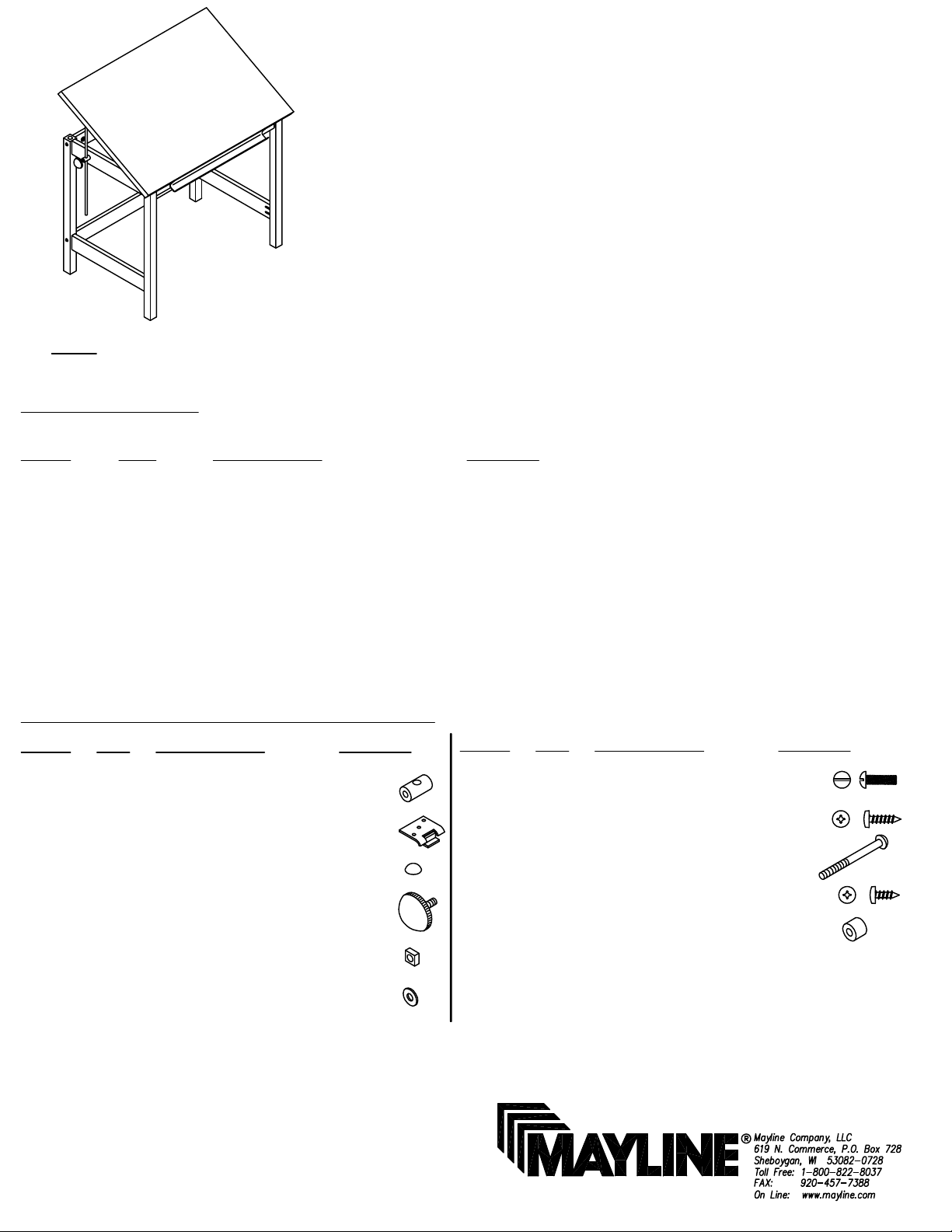
ASSEMBLY INSTRUCTIONS for
HARDWARE BAG (PART No. A7729)
FORESTER WOOD FOUR-POST
CATALOG No:
7602 7603
7604 7606
NOTE: Please count and inspect all pieces before disposing of any carton or packing materials.
COMPONENTS:
REF. # QTY. DESCRIPTION PART No.
1 1 TOP CALL~~
2 2 TILT ROD ASSEMBLY A315
3 1 L.H. TABLE END ASSEMBLY CALL~~**
4 1 R.H. TABLE END ASSEMBLY CALL~~**
5 1 FRONT RAIL ASSEMBLY CALL~~**
6 1 PENCIL TROUGH F249P
7 1 UPPER BACK RAIL CALL~~**
8 1 LOWER BACK RAIL CALL~~**
9 1 WELL BOTTOM CALL~~**
When ordering components, specific color and/or size information may be required.
Contact a Mayline Customer Service Representative. 1-800-822-8037
CATALOG No:
** Denotes Color Code
~~Denotes Size
7603LT
REF. # QTY DESCRIPTION PART No.
E1 2 TILT ROD GUIDE B160*
E2 2 UPPER HINGE B194*
E3 2 RUBBER BUMPER D38*
E4 2 KNOB K13*
E5 6 SQUARE NUT T12*
E6 2 WASHER W8*
*for individual item, order that part number
REF. # QTY DESCRIPTION PART No.
E7 2 5/16-18 x 1 1/4 SCREW X102*
E8 2 #10 x 1 SCREW X12*
E9 6 1/4-20 x 4 SCREW X210*
E10 12 #10 x 5/8 SCREW X5108*
E11 2 RUBBER BUMPER D10*
(1)
Page 2
7
Lower
Hinge
Groove
5
(Rough Side)
9
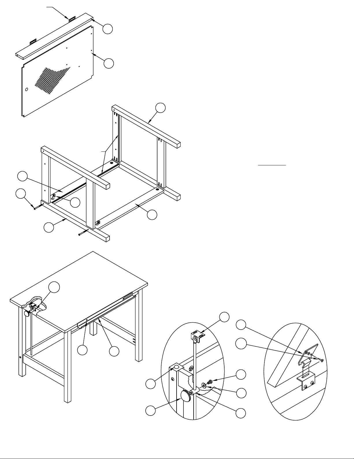
1. Position Table End Assemblies (3 & 4) as
shown per Fig. 1 and assemble Upper and
Lower Back Rail (7 & 8 - rails without hinges)
using Bolts (E9) and Square Nut (E5).
NOTE: Do no tighten any bolts until base is
fully assembled.
2. Align Well Bottom (9) into grooves with the
rough side down and hole cluster to the right
side of the assembly. Slide into position.
3. Attach Front Rail Assembly (5) using Bolts
4
(E9) and Square Nut (E5) per Fig. 1. Tighten
all previously assembled bolts on base.
Stand table up on legs.
4. Attach Tilt Rod Guides (E1) using Washer
(E6) and Screw (E7) per Fig. 3, do not bolt
tightly. Guides must swivel when top is tilted.
Slip Tilt Rod Assembly (2) through hole in tilt
rod guide at this time. LOOSELY hold in
place with Knob (E4).
5. Attach Rubber Bumpers (E3) to back legs.
E9
3
E10
E5
E8
Fig. 1
6
6. Align holes in Upper Hinge (E2) with holes
in underside of Top, attach with Screws
8
(E10) per Fig. 4.
7. Hold top in vertical position , insert ears of
upper hinge sections into slots in lower hinge.
Allow top to rest on Bumpers (E3) in
horizontal position per Fig. 4.
8. Attach Tilt Rod Assemblies (2) to top with
Screws (E10) per Fig. 2.
9. Attach Pencil Trough (6) with Screws (E8)
at desired position per Fig. 2.
(OPTIONAL if using 8187 Light Top)
2
E2
E10
Fig. 2
E3
E4
Fig. 3
(2)
E7
E6
E1
Fig. 4
Page 3

TO ATTACH OPTIONAL FOOTREST
CATALOG No:
7611 7611F
7612 7612F
E12
10
Table End Assembly
COMPONENTS:
REF. # QTY. DESCRIPTION PART No.
10 1 FOOT REST CALL~~**
HARDWARE BAG (A166)
REF. # QTY DESCRIPTION PART No.
E12 4 #10 x 3/4 SCREW X11*
NOTE: Attaching hardware is included with the footrest.
1. Position Footrest (10) at desired location from the front of the
table legs.
2. Attach Footrest to table end assembly using #10 x 3/4 Screws
(E12) which are provided.
When ordering components, specific color and/or size
information may be required.
Contact a Mayline Customer Service Representative.
1-800-822-8037
** Denotes Color Code
~~Denotes Size
* for individual item,
order that part number
CATALOG No:
7610
Holes in
Well Bottom
E13
3. Location may be marked and .149 diameter x 1/2 deep holes
pre-drilled in the table end rail, if you so desire.
TO ATTACH OPTIONAL STORAGE COMPARTMENT
COMPONENTS:
REF. # QTY. DESCRIPTION PART No.
11 1 SHELF B182
12 1 TRAY F9
HARDWARE BAG (A184)
REF. # QTY DESCRIPTION PART No.
E13 5 #10-24 x 1/2 SCREW X60*
E14 5 #10-24 KEPS NUT T2*
When ordering components, specific color
and/or size information may be required.
Contact a Mayline Customer Service
Representative. 1-800-822-8037
* for individual item,
order that part number
E14 11
NOTE: Attaching hardware is included with the Storage Unit.
1. Align holes in storage unit with pre-drilled holes in the Well Bottom.
2. Position the #10-24 x 1/2 Screws (E13) with the head in the Well
Bottom.
3. Tighten the #10-24 KEPS Nuts (E14)securely.
NOTE: Table shown with optional footrest.
(3)
Page 4

INSTALLATION INSTRUCTIONS
for 8187 Light Box to Forester Table
1"
1"
1 1/2"
1 1/2"
1. Mark the position for the Rubber Bumpers
(E11) on the top at the locations shown.
2. Thread Screw (E10) through the Bumper
(E11). Place the point of the screw at the mark
and tighten the bumper into position.
3. Position the Light Box over the Forester
worksurface with the Light Box Rod beyond
the end of the top and the pull toward the
front of the base.
Place the Light Box Rod down so that it
will be located under the worksurface. Slide
the Light Top forward till it touches the
bumpers.
(4)
 Loading...