

Page 1
(1)
ASSEMBLY INSTRUCTIONS
for DUAL COLUMN
2 and 3 STAGE BASES
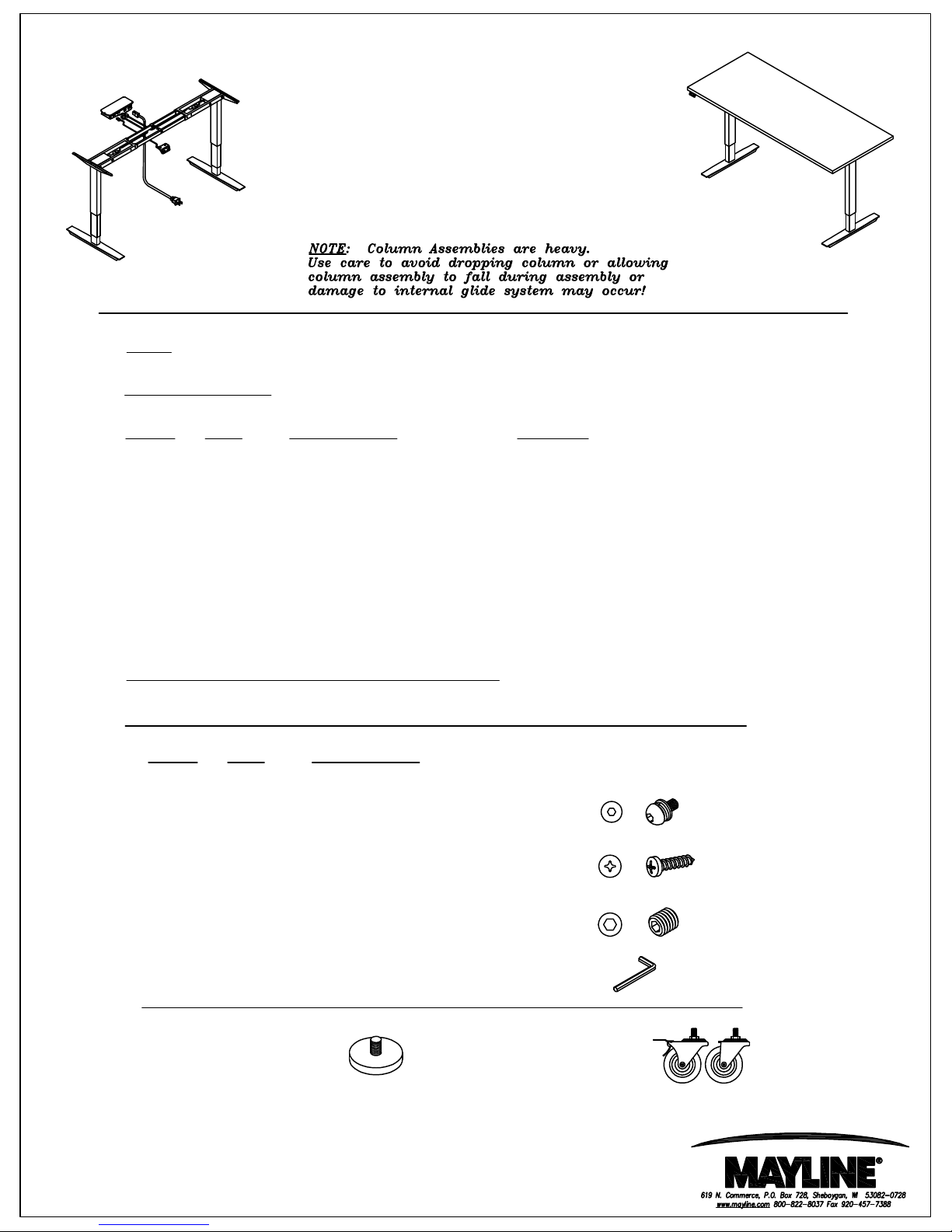
NOTE: Please count and inspect all pieces before disposing of any carton or packing materials.
COMPONENTS:
REF. # QTY. DESCRIPTION PART No.
1 2 LIFT ACTUATOR 2 2 FOOT w/LEVELERS 5122F2S (22" 2 Stage) - 5122FS (22" 3 Stage)
3 2 ACTUATOR FRAME 4 2 ADJ. CROSS BAR 5 2 TOP SUPPORT BRKT A9284S
6 1 CONTROL BOX Z529 (2 Stage) - Z530 (3 Stage)
7 1 STD. SWITCH 523SC
8 2 MOTOR CABLE 9 1 WIRE CHANNEL -
When ordering components, specific size information may be required.
Contact a Mayline Customer Service Representative. 1-800-822-8037
5126F2S (26" 2 Stage) - 5126FS (26" 3 Stage)
**OPTIONAL MEMORY SWITCH - 523MC
HARDWARE BAG (For any missing components order PART No. A9292)
REF. # QTY. DESCRIPTION
E1 12 M6 x 15mm MACHINE SCREW
LOCK WASHER
FLAT WASHER
E2 19 5x20mm PAN HD WOOD SCREW
E3 8 4mm SET SCREW
E4 1 4mm HEX WRENCH
REPLACEMENT LEVELER
QTY 1
PART# Q714
OPTIONAL CASTERS -QTY 4
2 LOCKING/2 NON-LOCKING
PART# Q715
Page 2
(2)
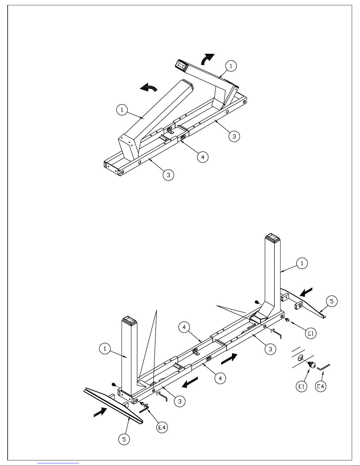
1. Remove the Actuator/Frame Assembly (Parts 1,3,4) from the carton and place on a clean
flat surface with the frame down.
2. Carefully unfold the Lift Actuators (1) to the vertical position.
3. Separate Actuator Frames (3) from Adj Cross Bars (4) enough to
expose the mounting holes in the Actuator Frame.
4. Insert Top Support Brackets (5) into Frame (3).
5. Fasten Actuator (1) to Frame (3) using Screw (E1). Tighten all screws.
**IMPORTANT: TIGHTEN THE TWO PRE-INSTALLED SCREWS
AT THE FRONT OF EACH ACTUATOR. SEE ILLUSTRATION.
6. Repeat Steps 4-5 for opposite side.
*Pre-Installed Screws
Page 3

(3)
7. Place Table Top down on a clean, flat, non-abrasive surface. Place Actuator/Frame
assembly in mounting location on top. Note: Use pilot holes and Top Support Brkt as a guide.
Note: Cross Bar adjustment will be required. Adjust Cross Bar (4) so Mounting Straps/Cord
Passage Holes are approximately centered in the frame.
8. Attach Actuator Frames (3), Cross Bars (4), and Top Support Brackets (5) to Top using
Screws (E2), Qty 10. Do Not Over-tighten.
9. Insert and tighten Set Screws (E3), Qty 6, into Frame (3). Do Not Over-tighten.
10. Attach Foot (2) to Actuator using Screws (E1), Qty 4 per Foot.
Page 4

(4)
11. Position Switch (7) on desired location on front edge of top, and fasten with
Screws (E4), Qty 2.
12. Position Control Box (6) and Wire Channel (9) in desired location, and fasten with
Screws (E4), Qty 7.
Page 5

(5)
13. Carefully plug Motor Cables (8), Switch Cord, and Power Cord into matching ports on
Control Box. Use the Diagram below as a guide.
14. Using one person per side, Carefully rotate table onto the base.
15. Plug power cord into outlet and proceed with Switch Initialization. See User Manual.
 Loading...