

Page 1
ASSEMBLY INSTRUCTIONS
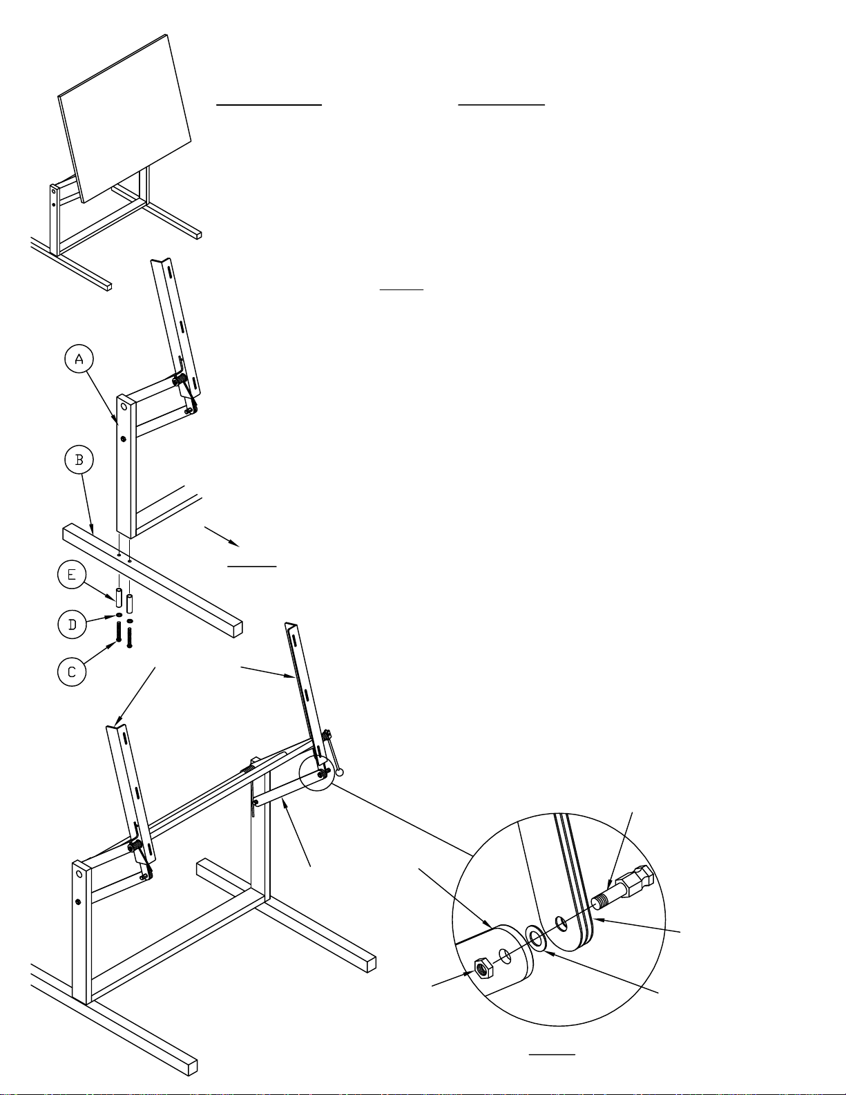
Washer (between Arm
COMPONENTS:
A. Stand Sub-Assembly.........1
B. Table Feet w/ Glides..........2
Table Mount
HARDWARE:
C. M8 x 80mm Socket Head Cap Screw...............4
D. Large Washer....................................................4
E. Sleeve................................................................4
F. Tension Cube.....................................................2
G. M8 x 16 Hex Head Screw..................................2
H. 13 mm x 17 mm Combination Wrench...............1
J. Spring Spanner Tube..........................................1
NOTE: Assembly is best performed by 2 people.
1. Remove the stand components from the shipping carton
and inspect for shipping damage. Reject if any damage is
evident.
2. Check the parts list to assure that the parts received are
the same as the parts required to assemble the unit. Also
assure the quantities are correct.
3. Assemble the Table Feet (B) to the bottom of the Stand
Sub-Assembly (A) with two Screws (C), two Sleeves (E), and
two Large Washers (D) per Foot. Position the longer portion
of the foot toward the front. Tighten these screws with
Combination Wrench (H) provided.
FRONT
4. Swing the table mount to a vertical position and carefully
release Brake Lever. Temporarily remove the nut from the
bolt holding the Brake Leaves. Swing Tilt Support Arm up
and slide arm onto end of brake leaf bolt. Tighten Hex nut to
secure Arm and Leaves. Repeat this step for both Tilt
Support Arms.
Tilt Support Arm
Hex Nut
(inside)
Brake Leaf Bolt
Brake Leaves
and Brake Leaves)
Fig. 1
Page 2

5. For the BOTTOM Height Assist tension springs, slide a Tension
Cube (F) over the short end of the Tension Spring. Align the tension
cube mounting hole with either hole in the support bracket.
NOTE: Use "FRONT" bracket hole for MORE assist
Use "REAR" bracket hole for LESS assist
Place the tension cube in the same position on both sides. Attach
with Hex Head Screw (G). Fig. 2
6. The UPPER Tilt Assist tension springs have tension cubes
installed on the Board Brackets for shipment. Assist for top control is
adjustable by position tension "UP" or "DOWN" as shown. Tension
Cube must be in same position on both sides. Tighten hardware for
both sides.
FRONT
Fig. 2
NOTE: Place Tension Cube "DOWN" for LESS assist. Fig. 3
Place Tension Cube "UP" for MORE assist. Fig. 4
Tension Cube
"DOWN"
Fig. 3
7. Charge Bottom and upper tension springs by placing Spanner Tube
(J) over the spring end and pulling the spring leg to its seat. Fig. 5 & 6
NOTE: USE EXTREME CAUTION WHEN CHARGING THE SPRING.
8. Attach the top to the board brackets using bolts supplied with Top.
Tension Cube
"UP"
Fig. 4
Fig. 5
Fig. 6
(2)
Page 3

ADJUSTMENTS:
(3)
This Base was designed to accommodate various top sizes:
NOTE: USE EXTREME CAUTION WHEN RELEASING OR
CHARGING THE SPRINGS
* If work surface lifts hard or to quickly, the tension cubes may be
adjusted per step 5 to increase or decrease 'LIFT' assist.
* If work surface tilts hard or tilts to fast, the tension cubes may be
repositioned per step 6 to increase or decrease 'TILT' assist.
* If work surface will not stay in position after placing tilt rod control in
LOCK position it may be necessary to increase tension on Brake
Leaves.
A). Release Tilt Control Rod and position work surface in vertical
position - do not lock Control Rod. Have second person hold work
surface and the Tilt Control Rod in this position. On the opposite
end of this pivot tube, turn Adjustment Nut 1/4 turn clockwise.
B). Position work surface at desired location and lock Tilt Control
Rod. If work surface does no stay in position, repeat above.
DO NOT OVER TIGHTEN damage to leaf springs and pivot tube
may occur. Tilt Control Rod may no engage or stay engaged in
locked position if overtightened.
Tilt Control Rod
Pivot Tube
Adjustment Nut
Shown with work
surface removed for
clarity only.
 Loading...