

Page 1
ASSEMBLY INSTRUCTIONS
DUAL ADJUSTABLE RACK
NOTE: Please count and inspect all pieces before disposing of any carton or packing materials.
COMPONENTS:
REF. # QTY. DESCRIPTION PART No.
1 2 BASE ANGLE WELDMENT A6977
2 4 RACK MOUNT RAIL CORNER CALL~~
3 4 SHORT ADJUSTABLE CHANNEL B7017
4 2 TOP BRACE B6483
When ordering components, specific size information may be required.
Contact a Mayline Customer Service Representative. 1-800-822-8037
~~Denotes Size
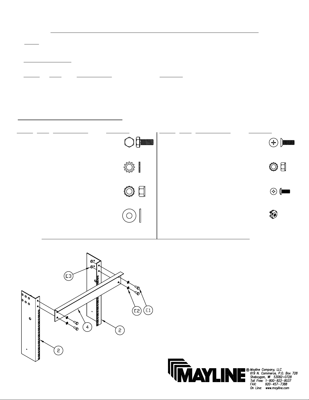
HARDWARE BAG (PART No. A7305) *for individual item, order that part number
REF. # QTY. DESCRIPTION PART No.
E1 22 5/16-18 X 3/4 SCREW X408*
E2 16 5/16 STAR WASHER W40*
E3 22 5/16-18 KEPS NUT T108*
REF. # QTY. DESCRIPTION PART No.
E5 32 1/4-20 X 3/4 SCREW X420*
E6 32 1/4-20 KEPS NUT T126*
E7 48 #10-32 X 1/2 SCREW X375*
E4 12 5/16 WASHER W30*
Fig. 1
E8 48 10-32 CAGE NUT T118*
1. Attach Top Brace (4) to Rack Mount
Rail (2) using Screws (E1), Washers
(E2) and Nuts (E3). See Fig. 1
(1)
Page 2
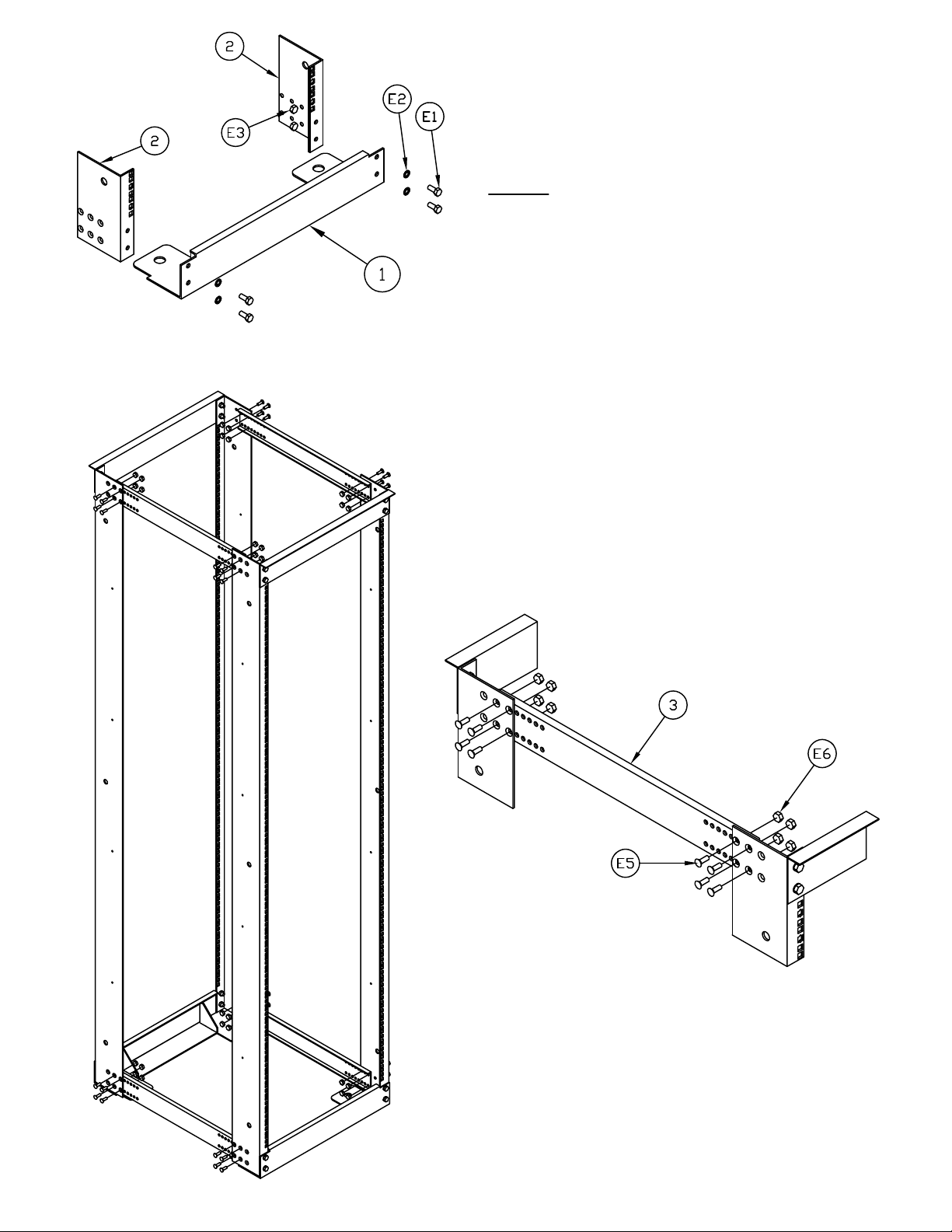
2. Attach Base Angle Weldment (1) to Rack
Mount Rail (2) using Screws (E1), Washers
(E2), and Nuts (E3). See Fig. 2
NOTE: Base Angle Weldment (1) installs as
shown to reduce foot print. Angle may be
installed in opposite direction to have mounting
holes for anchoring on outside of frame.
Fig. 2
3. Repeat steps 1 and 2 for opposite side of
rack.
4. Attach Short Adjustable Channel (3) and
Frame Assembly to desired depth using
Screws (E5) and Nuts (E6). See Fig. 3 and 3A
Fig. 3
Fig. 3A
(Adjusting Rack after assembly)
5. To adjust depth of Dual Rack, remove
Screws (E5), Nuts (E6), and Short Channel (3).
Reinstall at desired depth. See Fig. 3 and 3A
(2)
Page 3

Fig. 4
6. Select the desired height where
components will be mounted. Install Cage
Nuts (E8) into selected holes (2 per support).
TO INSTALL CAGE NUTS (E8):
A.) Place bottom of Cage Nut through
square hole from back side of rail (see detail
at right) allowing the lower portion of the Cage
Nut to grip the rail. See Fig. 4
B.) Compress the upper portion of the
Cage Nut with your thumb and snap Cage
Nut into place.
TO REMOVE CAGE NUTS (E8):
Compress Cage Nut with pliers.
(Additional Racks)
7. Attach Racks using Screws (E1), Washers
(E4), and Nuts (E3). (6 places) See Fig. 5
Fig. 5
(3)
Page 4

(Mounting Rack to floor)
8. To support the Maximum 1500 lbs. load rating Mayline requires the Rack to be
anchored to the floor before loading with equipment. Place the Rack in the desired
location and mark the floor mounting hole locations onto the floor. See Fig. 6 for
mounting hole location. Use the recommended hardware shown below dependent
upon floor style.
BASE ADJUSTABLE IN 1/2" INCREMENTS
UP TO 17.50 IN (21-26) DEPTH
UP TO 21.50 IN (27-32) DEPTH
(Not Supplied by Mayline)
A. Wood Floor
QTY. DESCRIPTION
4 3/8-7 x 2" Hex Head Lag Screw
4 3/8 Split Lock Washer
4 3/8 Fender Washer
B. Concrete Floor
QTY. DESCRIPTION
4 3/8-16 Concrete Anchors
4 3/8-16 x 3 1/2" Studs
4 3/8-16 Hex Nuts
4 3/8 Split Lock Washers
4 3/8 Fender Washers
(4)
 Loading...