

Page 1
Assembly Instructions
COMMUNICATION STATION
FREESTANDING WORKTABLES
NOTE: Please count and inspect all pieces before disposing of any carton or packing materials.
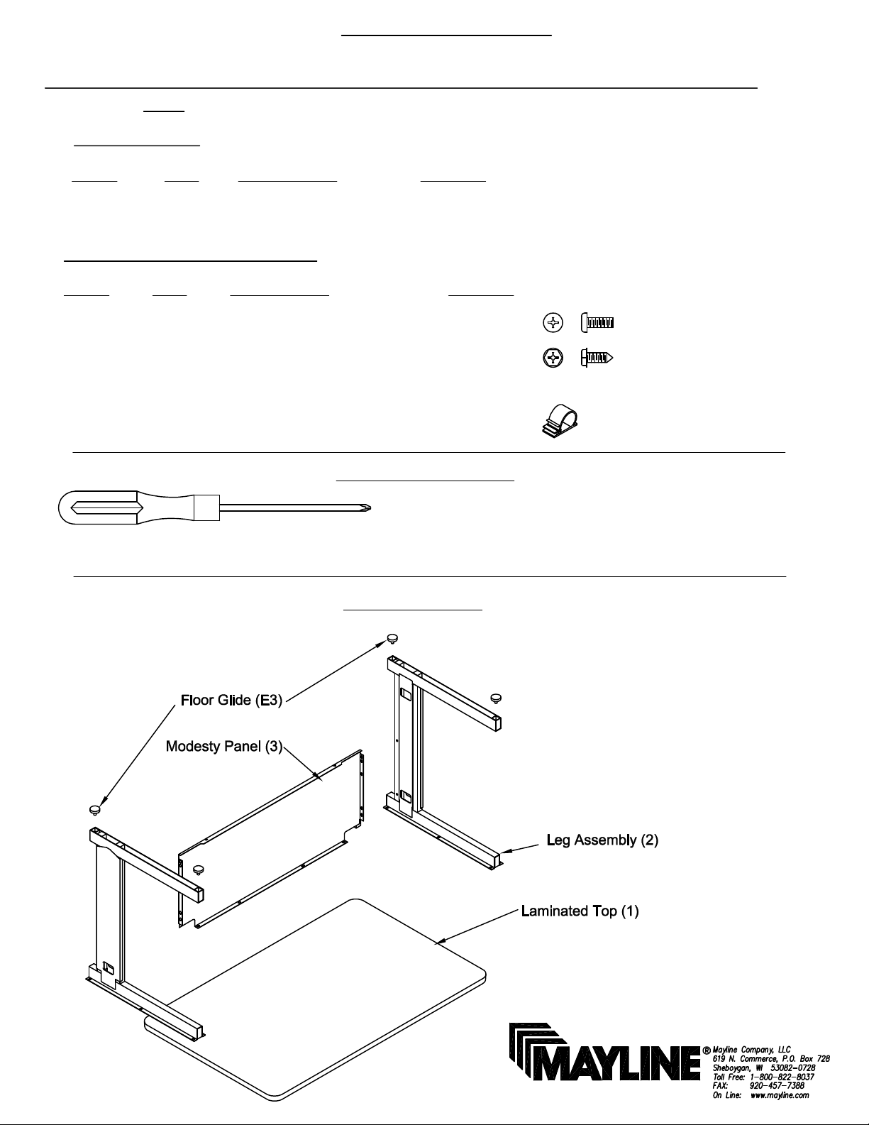
COMPONENTS
REF. # QTY. DESCRIPTION PART No.
1 1 Top CALL~~**
2 2 Universal Leg Assembly CALL~~**
3 1 Modesty Panel CALL~~**
HARDWARE BAG (PART No. 610008) *for individual item, order that part number
REF. # QTY. DESCRIPTION PART No.
E1 8 1/4-20 x 1/2" Pan Head Screw 7005*
E2 4 #12 x 3/4 Hex Head Screw 710232*
E3 4 Floor Glide 600128*
E4 2 Cable Clamps 9026
When ordering components, specific color and/or size information may be required.
Contact a Mayline Customer Service Representative. 1-800-822-8037
** Denotes Color Code
~~Denotes Size
Phillips Screwdriver
Tools required for assembly:
Note: A magnetic or power driver may be
used to assist in assembly.
Part Identification:
(1)
Page 2
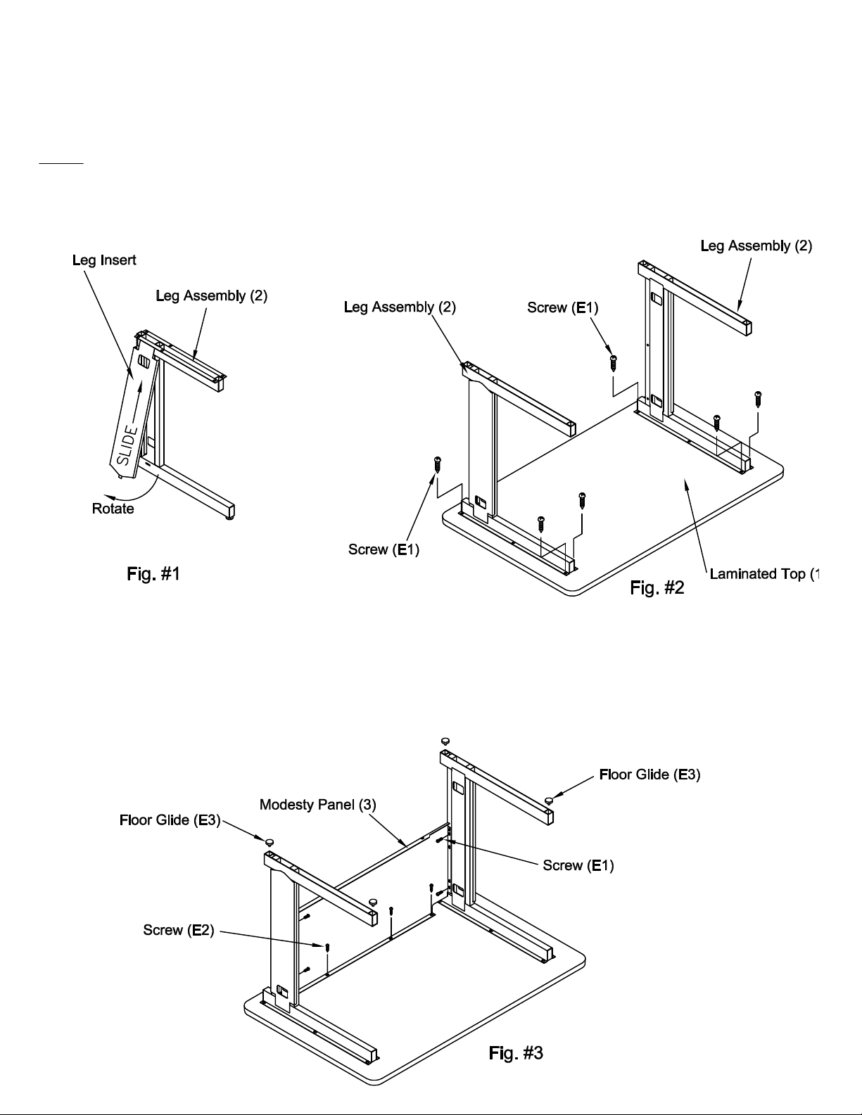
Assembly:
1. Begin assembly by placing the Laminated Top (1) upside down on a clean flat worksurface.
2. Locate and position the Universal Leg Assemblies (2). Secure by inserting and starting Screws (E1) through
the Leg assembly into the inserts installed in the Top. NOTE: Do Not tighten at this time.
NOTE: Universal Leg Assemblies (2) can be changed from right hand to left hand by removing the metal
inserts and installing them in the reverse position. See Fig. #1 To remove insert, slide the insert to the top of
the leg, rotate the bottom out, removing the tab from the cut out in the leg rail, then slide the top of the insert
from the top leg rail. Install in reverse order.
3. Attach the Modesty Panel (3) to the Universal Leg Assembly (2) with four Screws (E1). Secure the Modesty
Panel (3) to the Top (1) Using four Screws (E2). Tighten these screws first, then tighten all remaining screws.
4. Install the Floor Glides (E3) in the Leg Frames by inserting the threaded stud into the plastic sockets and
rotating clockwise.
(2)
Page 3
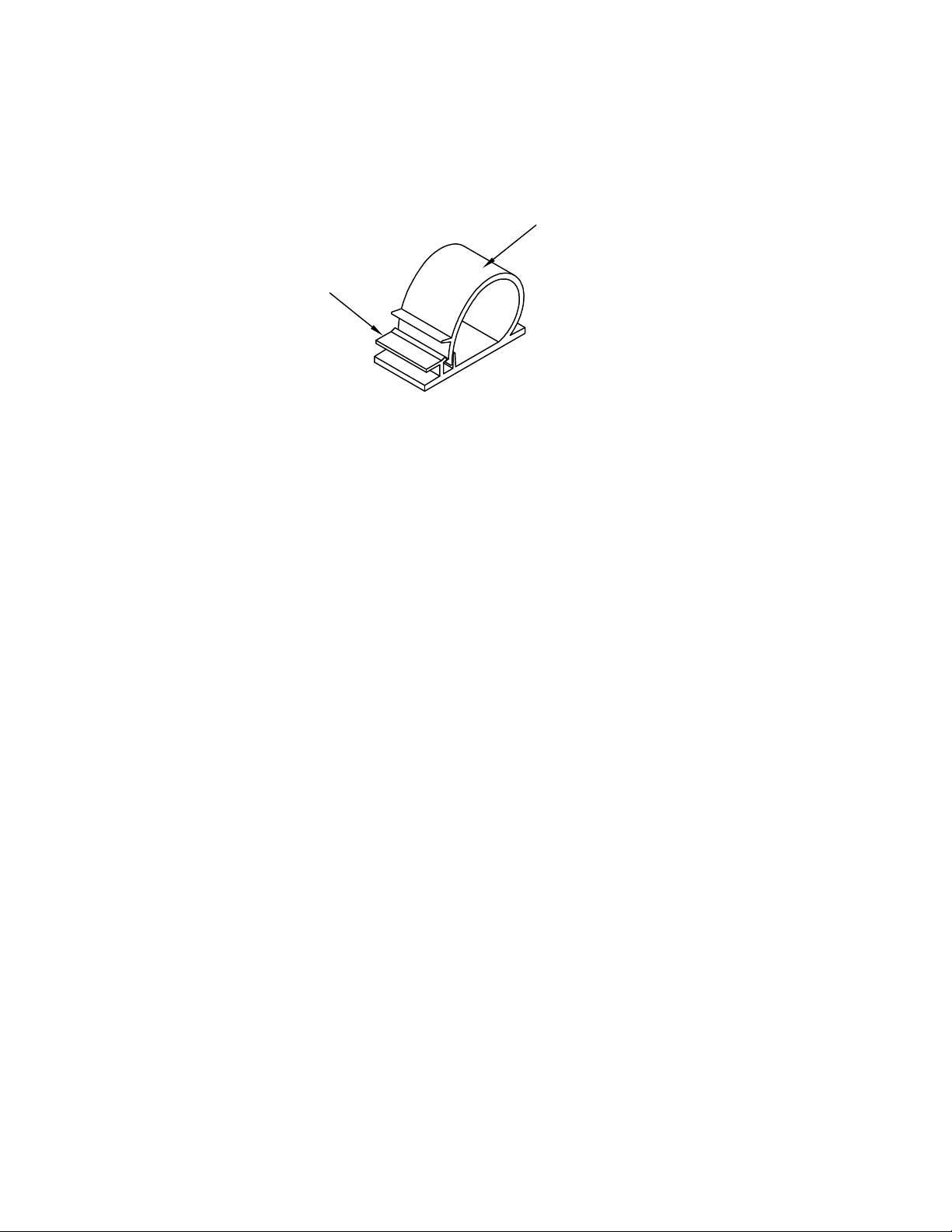
6. Cable Clamps (E4) are provided to assist with the organization of cables. To install the Cable Clamp,
determine the location and thoroughly clean the surface. Remove the paper backing from the Clamp and
firmly press the Clamp into position. To release the Clamp, press the release tab to allow the installation of
cables. To close, push on Clamp until it snaps shut
To Release:
PUSH TAB
.
To Close:
PUSH DOWN
P/N 150048 REV. 6 9-11
(3)
 Loading...